MPO/MTP Connector – Multi-fiber Connector for High Port Density

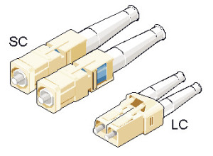
In today’s transmission networks, small and multi-fiber connectors are replacing larger, older styles connectors for space saving. For example, the SC connector is gradually being replaced by its small version LC connector which allows more fiber ports per unit of rack space. To save space, multi-fiber connector is also a good solution, like MTP/MPO connectors. MTP/MPO connector allows more fiber ports per unit of rack space and also satisfies parallel optical interconnections’ needs for multi-fiber connection. This article is to introduce MPO/MTP connectors in details.

MPO Connector & MTP Connector

MT ferrule

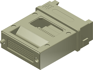
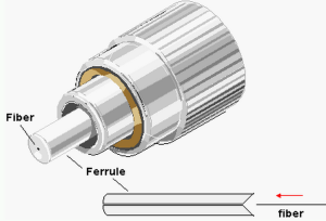
MPO is short for the industry acronym—”multi-fiber push on”. The MPO connector is a multi-fiber connector which is most commonly defined by two documents: IEC-61754-7 (the commonly sited standard for MPO connectors internationally) and EIA/TIA-604-5 (also known as FOCIS 5, is the most common standard sited for in the US). MPO connectors are based on MT ferrule (showed in the picture on the right) which can provide quick and reliable high performance interconnections up to 4, 12, 24 or more and are usually used with ribbon fiber cables. The following picture shows diagram of MPO connectors, 12-fold (left) and 24-fold (right). The fibers for sending and receiving are colorcoded, red and green, respectively.

mpo-mtp-connector-fiber-count

MTP stands for “Multi-fiber Termination Push-on” connector and it is designed by USConec and built around the MT ferrule. MTP connector is a high performance MPO connector designated for better mechanical and optical performance and is in complete compliance with all MPO connector standards. Some main improvements of MTP connector are as following:

  • The MTP connector housing is removable;
  • The MTP connector offers ferrule float to improve mechanical performance;
  • The MTP connector uses tightly held tolerance stainless steel guide pin tips with an elliptical shape;
  • The MTP connector has a metal pin clamp with features for centering the push spring;
  • The MTP connector spring design maximizes ribbon clearance for twelve fiber and multifiber ribbon applications to prevent fiber damage;
  • The MTP connector is offered with four standard variations of strain relief boots to meet a wide array of applications.
Application of MPO/MTP Connector

As mentioned, MPO/MPT connectors are compatible ribbon fiber connectors. MPO/MTP connectors cannot be field terminated, thus MTP/MPO connector is usually assembled with fiber optic cable. MTP/MPO fiber optic cable is one of the most popular MTP/MPO fiber optic cable assemblies, which are now being widely used in data center to provide quick and reliable operation during signal transmission. MPO/MTP connectors can be found in the following applications:

  • Gigabit Ethernet
  • CATV and Multimedia
  • Active Device Interface
  • Premise installations
  • Optical Switch interframe connections
  • Interconnection for O/E modules
  • Telecommunication Networks
  • Industrial & Medical, etc.
MPO/MTP Connector Selection Guide

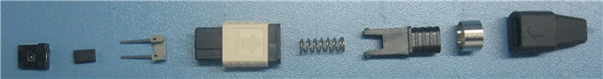
The structure of MPO/MTP connector is a little complicated. The picture below shows the components of a MPO connector.

MPO connector components

With the drive of market requests. Various types of MPO/MTP connectors are being provided. Some basic aspects should be considered during the selection of a MPO/MTP connector are as following:

mtp-mpo-connector-male-female

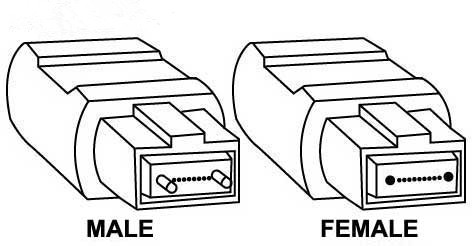
First is pin option. MPO/MTP connectors have male and female design (as showed in the picture on the left). Male connectors have two guide pins and female connectors do not. Alignment between mating ferrules of MPO/MTP connectors is accomplished using two precision guide pins that are pre-installed into the designated male connector. Second is fiber count: MPO/MTP connector could provide 4, 6, 8, 12, 24, 36, 64 or more interconnections, among which 12 and 24 are the most popular MPO/MTP connectors. In addition, like other fiber optic connectors, the selection of a MPO/MTP connectors should also consider fiber type and simplex or duplex design.

MPO/MTP Connector is a popular multi-fiber connector for high port density. It can offer ideal solution to set up high-performance data networks with the advantages of time saving and cost saving. As an important technology during migration to 40/100 Gigabit Ethernet, MTP/MPO connector is now being adopted by more and more data centers.

LC Connector Introduction

Fiber optic connectors are used to the mechanical and optical means for cross connecting fibers. Fiber optic connectors can also be used to join fiber cables to transmitters or receivers. There have been many types of connectors developed for fiber cable. Single mode networks have used FC or SC connectors in about the same proportion as ST and SC in multimode installations. But LC connector with smaller size and higher performance has become popular and the connector choice for optical transceivers for systems operating at gigabit speeds. The following text gives a detailed introduction of LC connector.

History of LC Connector

LC stands for Lucent Connector, as the LC connector was developed by Lucent Technologies as a response to the need by their primary customers, the telcos, for a small, low insertion loss connector. Then the LC design was standardized in EIA/TIA-604-10 and is offered by other manufacturers.

SC connector and LC connector

Advantages of LC Connector

There are solid reasons that the LC is the preferred connector for high-performance network. From the appearance, LC connect is like a mini size of SC connector. LC connector borrows split-sleeve construction and a cylindrical ferrule (usually ceramic) from SC connector. LC connector has a push-and-latch design providing pull-proof stability in system rack mounts. The picture on the right shows the appearance of SC connector and LC connector.

The ferrule size of LC connector is 1.25 mm which is half the size of SC connector ferrule—2.5 mm. LC connector is rated for 500 mating cycles and its typical insertion loss is 0.25 dB. An interesting feature of the LC is that, in some designs, the ferrule can be “tuned” or rotated with a special tool after it has been assembled. This offers a considerable performance advantage. The design and performance of LC connector address the need for high density and low insertion loss.

Application of LC Connector

LC connector can be found in many places for termination and connection, especially SFP transceivers for gigabit transmission. For example, the optic interfaces of Cisco SFP transceivers are all LC connectors. Some other applications are as following:

Simplex and duplex LC connectors

  • Telecommunication networks
  • Local area networks
  • Data processing networks
  • Cable television
  • Fiber-to-the-home
  • Premises distribution
LC Connector Selection Guide

To meet the needs of market, there are various types of LC connectors provided now. During the selection of LC connector, transmission media should be the first factor to consider. LC connector favors single mode fiber optic cable. But it can also be used with multimode fiber optic cable. Signals sometimes are transferred over simplex fiber optic cable and sometime duplex fiber optic cable. Thus, LC connector has both simplex and duplex design. The picture above shows an APC simplex LC connector on the left and a UPC duplex LC connector on the right. Some other factors like polishing style (APC or UPC), hole size and cable diameter should not be ignored. For more details about LC connectors, you can visit Fiberstore which provides various LC connectors with high performance and low price.

Introduction of PC, UPC and APC Connector

When we choosing a LC connectors, you might hear descriptions like LC UPC polished fiber optic connector, or LC APC fiber optic connector. Or when you are choosing a ST fiber optic patch cable, you can find the description like ST/PC multimode fiber optic patch cable. What do PC, UPC, APC stand for? The following text will give the explanations.

fiber optic connector ferrule

PC (physical contact), UPC (ultra physical contact) and APC (angle physical contact) are the polish style of ferrules inside the fiber optic connectors. Unlike copper cables with copper wire in the connectors as connection media, fiber optic connectors are with ceramic ferrules for connection. The picture on the left shows the ferrule in fiber optic connector. Different fiber optic connectors has different ferrule size and length. Also their polish style might be different.

To better understand the why we have PC, UPC and APC, let’s start with the original fiber optic connector which has a flat-surface and is also known as flat connector (showed in the following picture). When two flat fiber connectors are mated, an air gap naturally forms between the two surfaces from small imperfections in the flat surfaces. The back reflection in flat connectors is about -14 dB or roughly 4%. To solve this problem, the PC connectors came into being.

flat fiber connector

In the PC connector, the two fibers meet, as they do with the flat connector, but the end faces are polished to be slightly curved or spherical. This eliminates the air gap and forces the fibers into contact. The back reflection is about -40 dB. The following picture shows two end faces of PC connectors.

PC connector

UPC connector, usually has a blue-colored body, is an improvement to the PC connector with a better surface finish (as showed in the following picture) by an extended polishing. The back reflection of UPC connector is about -55 dB which lower than that of a standard PC connector. UPC connectors are often used in digital, CATV and telephony systems.UPC connector

PC and UPC connectors have reliable, low insertion losses. However, their back reflection depends on the surface finish of the fiber. The better the fiber gain structure, the lower the back reflection. If the PC and UPC connectors are continually mated and remated, back reflection will degrade. An APC connector won’t have such problem. Its back reflection does not degrade with repeated matings.

APC connector

APC connector usually has a green body with an end-face still curved but are angled at an industry-standard 8 degrees (showed in the above picture) which allows for even tight connections and smaller end-face radii. Thus any light that is redirected back towards the source is actually reflected out into the fiber cladding, again by virtue of the 8 degree angled end-face. APC ferrules offer return losses of -65dB. Some applications that are more sensitive to return loss than others that call for APC connectors, like FTTx and Radio Frequency (RF) applications. APC connectors are also commonly used in passive optical applications due to the fact that many of these systems also use RF signals to deliver video.

APC connector and UPC connector

PC, UPC or APC, which should be the choice of fiber optic connector? The answer is it depends. Choosing the appropriate connector for a fiber network depends on things such as, network design and function. Fiberstore offers a wide range of fiber optic connector as well as professional optical network solution. For more information you can visit Fiberstore.

1000BASE-T – Upgrade Your LAN Over Copper Cable

During the deployment of bandwidth-intensive applications over local area networks (LANs), many factors should be considered, like the speed, the infrastructure, the transmission media, etc. One of the most important things is the cost. Many LANs already use CAT-5 cabling. Replace these cables with fiber optic cable might cost a lot. For some companies which might have tight budgets and must leverage their existing infrastructure, 1000BASE-T would be a nice and cost-effective way to upgrade their LAN.

1000BASE-T Cable

What is 1000BASE-T?

1000BASE-T is Gigabit Ethernet that provides speeds of 1000 Mbps (1 gigabit is 1000 megabits per second) over four unshielded twisted pairs of cabling rated at Category 5/5e or better. 1000BASE-T specification allows a segment with a maximum length of 100 meters due to signal transmission limits, which can be used in data centers for server switching, LANs, for uplinks from desktop computer switches or directly to the desktop for broadband application. One of the advantages of 1000BASE-T is cost-effective.

A Cost-Effective Solution for Gigabit Ethernet

Fiber optic cables are gradually replacing copper cables in today’s telecommunication network. However, given the high cost of replacing copper cables with fiber optic cables and the low cost and good performances of 1000BASE-T, many companies might choose the 1000BASE-T system to upgrade their network and enjoy Gigabit Ethernet over copper cables. The following text illustrates the reasons why 1000BASE-T is one of the most cost-effective high-speed networking technology available.

SFP 1000BASE-T

  • No need to replace copper cables with fiber optic cables—it is known that copper solutions havtraditionally been lower than fiber-based solutions. As many companies still use Cat 5 twisted pairs, the replacing of copper into fiber optics will cost a lot of money and time. With the application of 1000BASE-T, companies can upgrades their local area network, data centers, etc. by using their existing copper cable place which would be time-saving and cost-saving.
  • No need to change Ethernet equipment and infrastructure investments—if you replace all the copper cables into fiber optic cables, you would be forced to replace cabling located in walls, ceilings, or raised floors. And the equipment connected to the fiber links should also be updated. It would be time-consuming and high-cost task, which won’t be the best choice of some companies with tight budget or lacking of time. With 1000BASE-T, these problems would be solved easily. 1000BASE-T preserves Ethernet equipment and infrastructure investments, including the investment in the installed Category 5 cabling infrastructure.
  • Flexible 100/1000 and 10/100/1000 connectivity—1000BASE-T support data rate ranging from 10 Mbps to 1000 Mbps. Flexible 100/1000 and 10/100/1000 connectivity will be offered and will enable the smooth migration of existing 10/1000 networks to 1000 Mbps-based networks. Used in conjunction with 1000BASE-T SFP, 1000BASE-T can provide highly cost-effective shared gigabit service. Various 1000BASE-T SFP transceiver modules that can enhance the performance of 1000BASE-T systems are being provided by current vendors.

1000BASE-T is a time-saving and cost-effective solution to upgrade the LANs to have Gigabit Ethernet. With the big advantage of cost-effective, 1000BASE-T are being widely applied. As technology advanced, various products are being provided to enhance the 1000BASE-T performances, like 1000BASE-T SFP module. Fiberstore provides a wide range of telecommunication products including 1000BASE-T SFP transceivers and Category 5/5e products. You can visit Fiberstore for more detailed information about 1000BASE-T.

Why Choose Direct Attach Cable in 40G/100G Migration?

Advance technologies like Big Data and Cloud which require high speed of data rate become more and more popular. To meet the ever growing need to high speed data transmission, many data centers are migrating from 10 GbE to 40 GbE or even 100 GbE. And some are considering about the migration, during which the cost is one of the most important factors to consider. Direct attach cable also known as DAC cable is a cost effective solution during the migration to 40GbE or 100GbE.

What Is Direct Attach Cable

A direct attach cable also known as DAC is usually a fixed assembly supporting high speed data that uses a small form-factor connector module as an optical transceiver on each end of a length of cable. With significant cost-saving and power-saving benefits, direct attach cable is now being widely used in data centers for short reach applications. It can be connected to switches, servers, routers, network work interface cards (NICs), Host Bus adapters (HBAs) providing high density and high data throughput.

Why Choose Direct Attach Cable

Direct attach cable with many significant benefits can satisfy the growing need for high speed data. The main benefits of direct attached cable are described in the following text.

Cost saving: the modules on the end of direct attach cable looks like optical transceivers. However, actually they very much different from optical transceiver. These small form-factor connector modules leave out the expensive optical lasers and some electronic components. That’s the main reason why the DAC is much cheaper than optical transceiver. Direct attach cable in some case can be an alternative to optical transceivers as it eliminates the separable interface between transceiver module and optical cable. Thus, choosing DAC in some cases can save a lot of money as well as time.

Low power consumption: to identify the modules on the end and cable type to the Ethernet interface, in both active direct attach cable and passive direct attach cable a small electrical component is used, which is low cost and consumes very little power compared with optical transceiver.

Supporting high data rate: DAC can provide high speed I/O (input and output) data. The most commonly used DAC can support high data rate of 10 Gb/s and 40 Gb/s. However, as technologies advanced, some vendor can provide direct attached cable supporting 120 Gb/s, like 120G CXP Cables.

Meet small form-factor standards: the modules on each end of DAC meet small form-factor standards which means DAC inherits some advantages of the small form-factor module, like space saving. Some time there is no need to upgrade the equipment by using a DAC.

40GBASE QSFP+ Direct Attach Cable

With various benefits like abilities in data transmission and cost saving, direct attach cable is becoming increasingly popular for short distance top-of-rack (ToR) and middle-of row (MoR) data center deployments. It’s a cost-effective solution to 40G/100G migration. Currently direct attach cable are continuing to evolve to meet industry needs. Various types of directive attach cable are being provided. FS.COM as a vendor of optical components provides DAC cable assemblies including 10G SFP+ Cables, 40G QSFP+ Cables, and 120G CXP Cables.

Related Article: Use High Speed Direct Attach Cable for Data Center Interconnection

Optical Transceiver Selection Guide

As an important optical component being widely used in today’s optical network, optical transceiver has been developing rapidly. More and more vendors are providing various types of transceivers to meet the market calls. To select a matching transceiver for a given application and hardware is now an easy thing now. Many parameters should be considered. The following text is to provide the parameters should be considered during the selecting of the proper optical transceivers.

MSA (Multi-Source Agreement) Type of Optical Transceiver

A transceiver is usually used to mechanically and electrically fit into a given switch and router. Transceiver MSAs define mechanical form factors including electric interface as well as power consumption and cable connector types. There are the following types of optical transceivers according to MSA: GBIC, XENPAK, X2, XFP, SNAP12, SFP, QSFP/QSFP+, CXP and CFP.

Protocol and Data Rate

As different switch or router supports different protocol and data rate. Before selecting the transceiver needed, make sure the protocol and data rate to be supported. The following provides the most common protocol and data rate types:

  • Gigabit Ethernet: 1 GE/10GE/40GE/100GE
  • Fiber Channel: 1GFC (1.25Gbps) / 2GFC / 4GFC / 8GFC / 16GFC
  • SDH STM-1 (155Mbps) / STM-4 (622Mbps) / STM-16 (2.5Gbps / STM-64 (10Gbps)
  • Multirate (155Mbps to 2.67Gbps)
  • CPRI up to 6Gbps (for Video Transmission)
Transport Media

The most commonly used transport media are cooper, single mode fiber (SMF), Multimode fiber (MMF). Maker sure the transport media, before choosing an optical transceiver.

Transceiver “Color”

The colored transceiver commonly known as CWDM transceivers and DWDM transceivers. In CWDM or DWDM system, each channel uses a different “color” transceiver because each lambd represents a different color in the spectrum.

Equipment Compatibility

In what switch or router is the transceiver supposed to work. Now the third party transceivers are being provided. If the equipment open for third party transceiver, then the third party transceiver could be an option. However, if not, the brand, model and firmware version must be known.

IEEE Descriptions

The functions of the optical transceivers are various, thus understand the IEEE descriptions of the optical transceivers can help to select the match one quickly. The following provided are the translation of IEEE descriptions:

  • MM: multimode
  • SM: single mode
  • Base -T: “copper” SFP with electrical RJ45 interface
  • SX: SFP 850nm, MM, grey, 1GE, approx. 500m
  • LX: SFP 1310nm, SM, grey, 1GE, approx. 8km
  • EX: SFP 1310nm, SM, grey, 1GE, approx. 40km
  • ZX: SFP 1550nm, SM, grey, 1GE, approx. 70km
  • CX4: “copper” XFP with electrical IB4x connector
  • SR: SFP+ or XFP 850nm, MM, grey, 10GE, approx. 300m
  • LR: SFP+ or XFP 1310nm, SM, grey, 10GE, approx. 10km
  • ER: SFP+ or XFP 1550nm, SM, grey, 10GE, approx. 40km
  • ZR: SFP+ or XFP 1550nm, SM, grey, 10GE, approx. 80km
  • SR4: QSFP 850nm, MM, 40GE, approx. 100m
  • SR10: CFP 850nm, MM, 100GE, approx. 100m
  • LR4: CFP or QSFP 1310nm, SM, 40GE (CFP or QSFP) or 100GE, approx. 10km

Fiberstore-CWDM-TransceiverTaking the above parameters into consideration, to select a match optical transceiver would be much easier and more quickly. FS.COM, an professional optical components provider, offers a wide range of optical transceivers of high quality including SFP, SFP+, CWDM transceiver, DWDM transceivers, etc.

How to Select the Right Fiber Patch Cable

A fiber patch cable, also known as fiber patch cord, which is widely applied to connect telecommunication equipment and backbone cabling, is a length of fiber optic cable capped at either end with connectors that allow it to be rapidly and conveniently connected to CATV, an optical switch or other telecommunication equipment.

As the fiber patch cables are used to cross-connect installed cables and connect communications equipment. The choice of fiber patch cable is very important to the performance of the network. Currently vendors offer fiber optic patch cables in a variety of cable and connector types. In order to select the right patch cable, some attributes needed to be obtained. They are fiber type, connector type on each end, simplex or duplex, jacket type and length. Fiberstore offers you the following tips to choose the proper fiber patch cable for your applications.

Choose the right fiber type—fiber patch cable should use the same fiber type as the fiber optic cabling that it is connected to. Fiber optic cable comes in two general types which are single-mode and multi-mode fiber.

LC-ST Duplex Multimode Fiber Patch Cable

Choose the correct connector type—the connectors on both end of fiber patch cable are used to connect to the patch panels and equipment. Connector types of the patch cable must match the patch panels and equipment. They can be the same and can also be different. For example, a fiber patch cable with a ST connector on each end is known as ST to ST patch cable. A fiber patch cable with a LC connector on one end and a ST connector on the other end is known as LC to ST patch cable.

Simplex or duplex—unlike copper patch cable which sends information in both directions, most fiber patch cord cables have a single strand of fiber allowing for signal flow in one direction only. A simplex patch cord is a single-fiber cable with simplex connection terminations. A duplex patch cord is a two-fiber cable with duplex connectors. Connecting equipment so that it can send and receive information requires two strands of fiber (one to transmit and one to receive information). This can be accommodated by using two “Simplex” (single strand of fiber) cables for each equipment interconnection or a “Duplex” cable, with conductors and/or connectors bonded together in pairs.

ST-ST-Fiber-Patch-Cable

Jacket of fiber patch cable—flammability of the jacket material could become an issue if the area they are in has special requirements for flame spread or products of combustion in case of a fire. To answer the market call, there are LSZH (low smoke zero halogen) fiber patch cable whose jacket is made of materials free of halogenated materials like fluorine (F), Chlorine (Cl), Bromine (Br), Iodine (I) and Astatine (At). This type of fiber patch cord won’t release low smoke zero halogen when it’s on fire.

Length—overall length of the patch cable may be specified in feet or meters, depending on your preference.

Fiberstore provides various types of fiber optic patch cables including single-mode, multi-mode, multi-core, armored patch cables, as well as fiber optic pigtails and other special patch cables. For most of the patch cables, the SC, ST, FC, LC, MU, MTRJ, E2000 connectors (APC/UPC polish) are all available. In addition, we also have MTP/MPO cables in stock.

Make the Right Choice of Splicing

Fiber splicing is used to permanently join two optical fibers where no additional changes are expected to be made to those fibers at that juncture. Compared with joints by connectors, fiber splicing typically results in lower light loss and back reflection.

There are two methods of fiber optic splicing: fusion splicing and mechanical splicing. Both of the two are functioning the same. However, they have their own advantages and disadvantages, which should be acknowledged before choosing of the methods of splicing which best fit the economic and performance objectives.

Fusion Splicing VS. Mechanical Splicing

The following text will make a comparison between mechanical splicing and fusion splicing from several aspects (process, time requested, performance and cost) to find the best choice of splicing.

The biggest difference between mechanical splicing and fusion splicing can be figured out by their literally meaning. Mechanical splicing is mechanically joining the fibers ends together which is quick and effective. While fusion splicing is a method of fusing fibers together using arc welding which is fairly complex and requires much more skill than mechanical splicing.

Process: The first three steps of mechanical splicing and fusion splicing before connecting the fibers ends are generally the same.
  • Step one: strip the protective coatings, jackets, tubes, strength members, etc. leaving only the bare fiber showing.
  • Step two: cleave the fiber with a fiber optic cleaver. The cleaved end for fusion splicing must be mirror-smooth and perpendicular to the fiber axis to obtain a proper splice. As to mechanical, the cleaving process is identical to the cleaving for fusion splicing but the cleave precision is not as critical.
  • Step three: clean the fiber.
  • Step four: after cleaning the fiber, the connecting step starts.
    For fusion splicing, fusing fiber contains alignment and heating. Once properly aligned the fusion splicer unit then uses an electrical arc to melt the fibers, permanently welding the two fiber ends together.
    Mechanical splicing does not need heating. Simply position the fiber ends together inside the mechanical splice unit. The index matching gel inside the mechanical splice apparatus will help couple the light from one fiber end to the other.
  • Step five: protect the fiber
    Fusion splicing—using heat shrink tubing, silicone gel and/or mechanical crimp protectors will keep the splice protected from outside elements and breakage.
    Mechanical splicing—the completed mechanical splice provides its own protection for the splice.

fusion-splicing-tools

Time Requested: mechanical splicing is fast and effective, which is suitable for some emergency situations. However, fusion splicing is more skilled and need more time to be finished.

Performance: with mechanical splicing, the fibers usually have loss of 0.3dB. However, with fusion splicing, the fibers generally have a loss of 0.1dB and the fiber splices are usually stronger.

Cost:mechanical splicing has a low initial investment ($1,000-$2,000) but costs more per splice ($12-$40 each). While the cost per splice for fusion splicing is lower ($0.50-$1.50 each), the initial investment is much higher ($15,000-$50,000 depending on the accuracy and features of the fusion splicing machine being purchased). The more precise you need the alignment (better alignment results in lower loss) the more you pay for the machine.

Many companies now invest fusion for networks, especially for long haul single-mode networks. However, they also use mechanical splicing for shorter, local cable runs. Consider the requests for performance quality, time, situations and the capacity of economics before choosing the fittest method of splicing.

Could Dark Fiber Light Up the Future?

Most of today’s data transporting are based on fiber optic network, which has faster speed and larger scale than ever before. However, needs for the data transporting capacity are still growing rapidly. The fiber optic network operators and providers usually lay more fiber optic cables than what is needed to avoid installing the fiber cables again and again, which also curbs the costs efficiently. These additional fiber cables are known as dark fiber or unlit fiber.

Dark fiber is optical fiber that has been installed and ready for use but is not currently being used, which has no electronics on either ends.

Dark fiber is primarily needed by operators taking into account the increasingly high demands of the end-user. Now the dark fiber can be leased or sold to individuals or companies who wants to create their own privately-operated optical fiber network rather than just leasing bandwidth or wants super fast speed and a highly secure network. The dark fiber network can be set up in a variety of ways, including dark fiber rings, point to point or point to multipoint.

dark-fiber

Benefits of Dark Fiber
  • Capacity: Dark fiber is a network of fiber optic cables that can carry high amounts of data at high speeds over hundreds of miles. Dark fiber also has unlimited expansion capability.
  • Flexible & Freedom: With dark fiber, the choice of network equipment would be more flexible. Individuals can choose the network equipment that supports the specific requirements.
  • Security: Fully dedicated, private physical network infrastructure.
Limits of Dark Fiber
  • Cost: the price for high performance dark fiber network is not low. Lighting up dark fiber requires maintenance and management. The time and equipment spent on lighting up the dark fiber is also an important part of the expense.
  • Location: Dark fiber networks are generally only available in the areas where fibers have already been installed which limits the application of dark fiber network. Dark fiber network is typically run between data centers and other places with existing fiber infrastructure.

As more and more individuals and companies look for platforms to improve internet bandwidth and data connectivity, dark fiber has become a popular topic. The performance of dark fiber is seductive. However, cost and limits of dark fiber should also be considered. There are many companies providing high performance dark fiber network, like Google whose price is very high. While the availability of WDM reduced the demand for fiber optic, which lower the price of dark fiber in some extend. The future of dark fiber is still in arguing and discussing.

Fiber Optic Cleaning – Fight Against Dust

Fiber optic connectors are very sensitive to contaminants like dust, oil and other dirt which can have great impact on the overall optical network, and can reduce its performance and maximum distance. Dust as small as 1 µm can have a noticeable effect on the connector’s attenuation (in excess of 0.5dB). Thus, fiber optic cleaning is one of the most basic procedures to main the operation of optical network system. It’s no exaggeration to say that cleaning consideration is the number one issue in fiber optic cable technology today.

Dust Is Everywhere

It seems that the dust, one of the biggest enemy in the fiber optic communication system, can always find its way to reach the fiber optic connector interface. When a fiber optic connector is mated or unmated, both the plug and receptacle might be polluted by the dust, oil from our fingers or other contaminants. The oil can leave a noticeable defect on the interface of the fiber optic connector, the oil also tends to trap dust against the fiber. To maintain the well operation of optical network, many fiber optic cleaning products and methods are being invented to fight again contaminants like dust.

Tips on Fiber Optic Cleaning

There are two main methods of cleaning based on the material used to clean the fiber optic. One is known as dry clean which is optic cleaning without using any solvent, the other is wet clean during which solvent, usually IPA (isopropyl alcohol) is used. Sometimes, the two methods should be combined. The following picture shows the suggested cleaning approach.

fiber optic cleaning process

The following are some tips which might be useful during fiber optic cleaning:

  • Both sides of the connectors should be cleaned, as dirt might be transferred from one to the other.
  • Keep dust caps on the connector, but do remember to verify that the dust caps are clean.
  • Do not just clean the end-face. The body of the connector ferrule should also be cleaned.
  • Do the cleaning in a clean, low-dust environment
  • You should not touch any transmissive or reflective surface of your optic and never reuse a lens tissue.

With proper handling and cleaning of your fiber optic, you can prevent damage and ensure their continued performance.

EDFA Selection Guide

An EDFA is an optical amplifier based on Erbium-doped optical fiber, that amplifies optical signals without converting them into electrical form. EDFAs use semiconductor lasers to pump Erbium Doped Fiber to amplify light in 1.5 μm wavelength region where telecom fibers have their loss minimum. It has low noise and can amplify many wavelengths simultaneously, which makes DWDM network possible and becomes a key enabling technology for optical communication networks. Since the realization of EDFA, it has developed rapidly and has become the amplifier choice for most applications in optical communication.

Basic of EDFA

The structure and working principle of an EDFA are simple. EDFA consists of a glass optical fiber doped with Erbium ions, WDM coupler, isolators, optical filter and pumping supply.EDFA

The picture above shows how an EDFA works. When a beam of light that carrying signals passes the Erbium-doped optical fiber, a pump laser provides the amplifier energy at Erbium absorption peaks of 980 and 1480 nm, through the use of WDM couplers. Then an optical filter removes the remaining traces of the pump beam so that it doesn’t interfere with reception of the signal. Isolators are inserted into the amplifiers to minimize the reflections on the EDFA

How to Choose the Right EDFA

First of all, you should make sure the network type in which you need to use EDFA. Depending on the network application, EDFA are generally designed into the following types:

  • DWDM EDFA: for this type of network, EDFA needs to be not only high power low noise, but also gain flattened such that all wavelength channels can be amplified equally.
  • SDH EDFA: For SDH network, EDFA design should allow maximum power budget to achieve the highest detection sensitivity.
  • CATV EDFA: There is also EDFA designed for CATV application, which has low noise with heat dissipation and ventilation in mind to ensure a long operation life.

The way in which EDFA used is to enhance the performance of optical data links is also important in selecting EDFAs. Depending on this, three types of EDFAs can be found in the market:

  • Booster EDFA: this EDFA is used to increase the optical output of an optical transmitter just before the signal enters an optical fiber.
  • Inline EDFA: as the optical signal is attenuated as it travels in the optical fiber. The inline amplifier is used to restore the optical signal to its original power level.
  • EDF pre-amplifier: this kind of EDFA is used at the end of the optical link in order to increase the sensitivity of an optical receiver.

Some other important elements should be considered before selecting EDFAs.

  • Wavelengths: you should make certain how many wavelengths will go through the EDFA and the beginning and ending wavelengths, for example 1530 to 1562 nm. For single wavelength link, you should know clearly the exact wavelength.
  • Power or loss budget: the budget tells us how much amplification you require for the whole link.
  • The location of EDFAs: After the transmitter, before the receiver, or in the mid-span.

Fiberstore DWDM EDFA
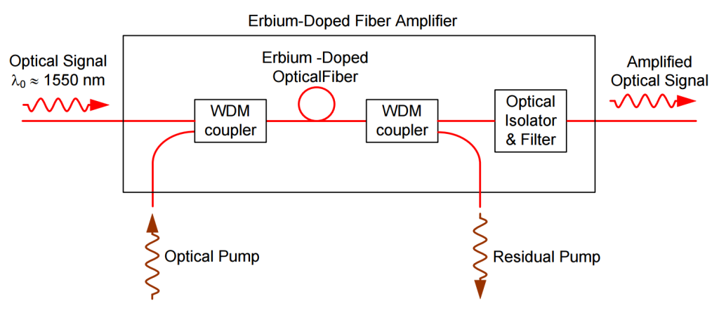
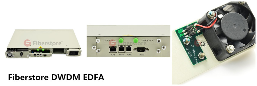
Selecting the right EDFA seems not an easy thing. However, if you are not sure about the types and numbers of EDFAs, you can visit FS which supplies various EDFAs with high quality and low price, as well as free EDFA solutions meeting customers’ requests.

Do Not Miss FS’s 40-Channel DWDM Multiplexer/Demultiplexer with the Lowest Price

DWDM (Dense Wavelength Division Multiplexing), an ideal optical multiplexing technology for long-haul data transporting, can put multiple channels of information using individual wavelength on the same fiber and increase the transmission capacity of optical networks considerably. Currently, DWDM technology is being widely applied in telecommunication networks and becomes the choice of many telecommunication operators.

Since the start of DWDM, various equipment and technologies have been used to enhance the high performance of every part of DWDM network. DWDM Multiplexer and demultiplexer are the main equipment that takes charge of the data sources’ multiplexing and demultiplexing. In the past years, DWDM multiplexers and demultiplexers have been upgraded rapidly to overcome the insertion loss and to meet the demands of the increasing requests for faster telecommunication, and they are always being combined in one rack by today’s vendors also known as DWDM Mux/Demux.

FS as a serious manufacture of optical communication published a 40-channel Duplex DWDM Athermal AWG Mux/Demux with competitive features which are described as following.

Fiberstore 40-channel DWDM Mux/Demux

Low Insertion Loss: Insertion loss is an inevitable problem in optical networks. Combining LC/UPC connectors of high quality and AWG technology, this duplex Mux/Demux reduces the insertion loss to a minimum of 3dB and increases the transmission capacity effectively.

Athermal AWG Technology: With athermal design this mux/demux device is temperature-intensive and allows multiplexing and demultiplexing of DWDM signals over a wide operating temperature range with long-term stability, reliability and large transmission capacity.

Large Channel Number & Excellent Channel Isolation: This DWDM Mux/Demux is designed for use within the C-band release of DWDM system which uses 40 channels at 100GHz spacing containing the channels from C21 (wavelength: 1560.606 nm) to C60 (wavelength: 1529.553 nm). Also 1.6nm (200 GHz) are available on request. Excellent channel isolation that eases the fiber handling is also provided.

Space-saving: With a standard 19-inch rack mount housing size, this DWDM Mux/Demux saves space effectively.

High quality and Inexpensive: The products of FS has been appreciated by customers for its reliable quality. Comparing with other manufactures, FS offers the lowest price for such a high quality 40-channel DWDM Mux/Demux.

40-Channel DWDM Mux/Demux

For detailed specifications of this low insertion loss 40-channel Duplex DWDM Athermal AWG Mux/Demux with Monitor Port, please visit FS’s online shop. FS currently has 10 of this DWDM Mux/Demux in stock and can deliver on the same day of ordering. FS also provides a custom package to meet customers’ requirements.

Some Common Fiber Optical Transceiver

Fiber optic transceiver including both transmitter and receiver in a single module is an important equipment transmitting and receiving data to support the normal operation of optical fiber data transmission system. The market currently offers a wide selection of fiber optic transceiver for use with different types of wire, fiber and wavelength and so on.

A group of companies joined together to agree on package standards also called multisource agreements (MSAs). The package standards help customers choose the best transceivers to their applications and make sure the they can use transceiver from multiple vendor without redesigning the board. In the following text, some common fiber optic transceivers according to package standards are introduced in details.

9-PIN&GBIC&SFF
9-Pin transceiver
 is also known as 1×9 optical transceiver. This transceiver has a single row of output pins at the rear of the device. The optical interface is usually ST or duplex SC receptacles. It is mainly used in fiber optic transceiver, optical switches, single/multi-mode converter as well as some industrial control applications.

GBIC transceiver, namely gigabit interface converter transceiver, is a plug-in interface designed to allow a pluggable interface for Gigabit Ethernet. It offers a standard, hot swappable electrical interface and can support a wide range of physical media from copper to long-wave single mode optical fiber, at lengths of hundreds of kilometers. However, this type of transceiver is gradually replaced by SFP transceiver which has more advantages.

SFF (small form-factor) transceiver is a compact optical transceiver used in optical communications for both telecommunication and data communications applications. Compare to 9-pin and GBIC transceivers, SFF transceivers is smaller allowing more ports in a given area. SFF transceivers have 10 or 20 I/O (input/output) pins that solder to the board.

SFP&SFP+&XFPSFP transceiver, small form-factor pluggable, small hot-pluggable optical module is a pluggable version of SFF transceiver and an upgraded version of the early GBIC module, with 10 I/O connections at the rear of the package. With smaller volume and higher integration, it is currently the most popular fiber optic transceiver.

SFP+ transceiver, also called enhanced SFP or SFP plus, with a higher transmission rate usually up to 8.5 G or 10 G, is a kind of optical transceiver module specified for 8Gbps/10Gbps/16Gbps fiber channel and 10Gigabit Ethernet applications.

XFP transceiver, 10Gigabit small form-factor pluggable transceiver, is the next generation SFP transceiver for 10Gbps application. This type of transceiver is hot-swappable and protocol-independent and is usually used to 10Gbps SONET/SDH, fiber channel, Gigabit Ethernet and other applications, but also of CWDM DWDM link.

X2&XENPAK
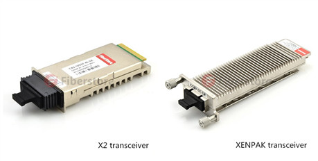
XENPAK transceiver is a pluggable transceiver for 10Gbps applications, specifically 10 Gigabit Ethernet. The electrical interface is called XAUI, which provides four 2.5Gbps signals to the transmitter, which multiplexes or serialize them into a single 10Gbps signal to drive the source. It uses a 70-pin electrical connector. The optical interface is usually a duplex SC.

X2 transceiver is based on the XENPAK transceiver standards. It is shorter than XENPAK transceiver but uses same 70-position electrical and duplex SC interfaces. Unlike XENPAK, X2 devices mount on top of the board and are low enough to allow boards to be stacked side by side.

Introduction of Fiber Optic Sensor

Optical fibers are mainly applied in telecommunications, which has significantly changed this industry. However, there is also a growing application of optical fibers in sensing applications for measurement. Many components associated with optical fibers are developed to sensing applications. One of the most significant components—fiber optic sensor (also known as optical fiber sensor) is now being widely used in sensing applications.

Fiber optic sensors are fiber-based devices to sense some quantities like temperature, pressure, vibrations, displacement, rotations or concentration of chemical species. The basic instrumentation required for sensor are optical source (often a single-frequency fiber laser), sensing element, optical detector and end-prossesing devices (optical-spectrum analyzer, oscilloscope). A block diagram of fiber optic sensor is showed in the following picture.

8-30-2014-10-06-53-AM

Fiber optic sensor offers a wide range of advantages, which makes it being applied in many field successfully. Its advantages are as following.

  • Explosion proof: In fiber optic sensor, the primary signal is an optical. Therefore, there is no risk of spark or fiber.
  • Immunity to electromagnetic interference: Since the fibers are composed of dielectric such as glass. The fiber optic sensor is immune to radio frequency and electromagnetic.
  • Small size, light weight and flexible: This feature extends the applications of fiber optic sensor to many fields, like aircraft.
  • High sensitivity: The optical fiber sensors are highly sensitive and have large bandwidth. When multiplexed into arrays of sensors the large bandwidths of optical fibers themselves offer distinct advantages in their ability to transport the resultant data.
  • Remote sensing: With the availability of low loss optical fibers, the optical signal can be transmitted up to a long distance transmitted up to a long distance (10-1000m). Thus the remote sensing is possible with the optical fiber.
  • Environmental ruggedness and resistant: The optical fiber are manufactured from non-rusting materials such as plastics or glasses, therefore, the fibers have excellent stability when in permanent contact with electrolyte solutions, ionizing radiation etc. Further the fibers can withstand high temperature as high as 350 ca. Special fibers can extend sensor operation beyond 350c to as high as 1200c.
  • Compactness: With the availability of solid-state configurations (small size sources and detectors) it is possible to design a compact optical fiber sensor system.

Based on the sensor location, the fiber optic sensors are generally classified into two types, namely intrinsic and extrinsic fiber optic sensor.

Intrinsic fiber optic sensor can provide distributed sensing over very large distances, which is the most useful feature of it. In intrinsic fiber optic sensor, sensing takes place within the fiber itself. Only a simple source and detector are required. This sensor depends on the properties of the optical fiber itself to convert an environmental action into a modulation of the light beam passing through it. The basic concept of the intrinsic fiber optic sensor is showed in the picture below.

Intrinsic fiber optic sensor

Extrinsic fiber optic sensors use an optical fiber cable, normally a multimode one, to transmit modulated light from either a non-fiber optical sensor, or an electronic sensor connected to an optical transmitter. In this sensor, the fiber may be used as information carriers that show the way to a black box. It generates a light signal depending on the information arrived at the black box. The black box may be made of mirrors, gas or any other mechanisms that generates an optical signal. These sensors are used to measure rotation, vibration velocity, displacement, twisting, torque and acceleration. The major benefit of these sensors is their ability to reach places which are otherwise unreachable. The best example of this sensor is the inside temperature measurement of the aircraft jet engine. The following picture shows the basic concept of the extrinsic fiber optic sensor.

Extrinsic fiber optic sensors

Fiberstore offers fiber optic sensors of high quality. For more information about fiber optic sensor, you can visit its online shop.

Basic of PON

PON, namely, Passive Optical Network, is a telecommunications network that uses ponit-to-multipoint fiber to the premises in which unpowered optical splitters are used to enable a single optical fiber to serve multiple premises. It is an optical-fiber-based network architecture that can provide much higher bandwidth in the access network compared with traditional copper-based networks and is regarded as an ideal solution to last-mile bandwidth bottlenecks. Some of the most primary PON parts and their functions will be introduced in the rest of this article.

Passive optical network

PON consists of an Optical Line Termination (OLT) at the service provider’s Central Office (CO), a number of Optical Network Units (ONUs) and Optical Network Terminals (ONTs) near end users and Optical Distribution Network (ODN) within which optical fibers, fiber optic connectors, passive optical splitters, and auxiliary components collaborate with each other. The above picture shows passive optical network system applied in FTTH/FTTB/FTTC/FTTCab.

OLT is located at the CO. Its main function is to control the information float across the ODN, going both directions. OLT has two float directions: one is upstream getting an distributing different type of data and voice traffic from users, the other is downstream getting data, voice and video traffic from metro network or from a long-haul network and sending it to all ONT modules on the ODN.

Fiberstore EPON ONU with 1-PON Port and 8 10100M ports  Fiberstore OLT with 8-PON Ports

ONT and ONU are basically the same device. ONT is at the customer’s premises to use optical fiber for connecting to the PON on the one side, while interfacing with customers on the other side. ONU receives optical signal and converts it into an electrical signal. However, it is located outside the home, working in different temperature and weather conditions. Thus, ONU should resist water, winds and vandals. There should be an emergency battery backup in ONU in case that the power is off.

ODN containing optical fibers, fiber optic connectors, passive optical splitters, and auxiliary components, is an indispensable path for transmitting PON data and directly affects the performance, reliability, and scalability of a PON system.

Splitter Singlemode Dual Window 250µm Bare Fiber SplitterFiberstore ONT with 2 pots and wifi

The passive optical splitter or PON splitter in ODN is the main part of PON being passive. With a single PON splitter taking one input cable, 32 or 64 subscribers can be served at the same time. In PON the splitters can be arranged in star, ring or tree configurations to increase reliability. There are mainly two kinds of passive optical splitters: one is the traditional fused type splitter as known as FBT coupler or FBT WDM optical splitter, which features competitive price; the other is the PLC splitter based on the PLC (Planar Lightwave Circuit) technology, which has a compact size and suits for density applications.

Fiberstore PON Solution

The mentioned components are the basic parts of PON.  Fiberstore focusing on optical communication for more than 14 years in both technology and manufacturing, can offer perfect PON solution according to customers’ needs. All the mentioned components can be found in the online store of Fiberstore, including but not limited to: OLT, ONT, ONU, splitter, optical fiber and connectors.

7 Factors to Consider before Selecting An OTDR

An OTDR (Optical Time Domain Reflectometer) is a fiber optic tester for the characterization of optical networks that support telecommunications. The purpose of an OTDR is to detect, locate, and measure elements at any location on a fiber optic link. An OTDR needs access to only one end of the link and acts like a one -dimensional radar system. By providing pictorial trace signature of the fibers under test, it’s possible to get a graphical representation of the entire fiber optic link.

Fiberstore2405 OTDR

An OTDR can be used to measure optical distance including locations of the elements like splices, connectors, splitters, multiplexers and faults, as well as end of fiber. Loss and Optical Return Loss (ORL)/Reflectance, such as loss of splices and connectors, ORL of link or section, reflectance of connectors and total fiber attenuation can also be tested by OTDRs.

Not all OTDR are made the same. There are various kinds of OTDR models available, addressing different test and measurement needs. The choosing of an OTDR is based on applications. By thinking of the following questions, you can roughly know what kind of OTDR you need.

  • What kind of networks will you be testing? LAN, metro, long haul?
  • What fiber type will you be testing? Multimode or single-mode?
  • What is the maximum distance you might have to test? 700 m, 25 km, 150 km?
  • What kind of measurements will you perform? Construction(acceptance testing), troubleshooting, in-service?

JDSU MTS-4000 OTDR

Fiberstore offers you 7 factors to help you figure out which OTDR best fits your applications.

  • Size and Weight: important if you have to climb up a cell tower or work inside a building.
  • Display Size: 5″ should be the minimum requirement for a display size; OTDRs with smaller displays cost less but make OTDR trace analysis more difficult.
  • Battery Life: an OTDR should be usable for a day in the field; 8 hours should be the minimum.
  • Trace or Results Storage: 128 MB should be the minimum internal memory with options for external storage such as external USB memory sticks.
  • Bluetooth and/or WiFi Wireless Technology: wireless connectivity enables easily exporting test results to PCs/laptops/tablets.
  • Modularity/Upgradability: a modular/upgradable platform will more easily match the evolution of your test needs; this may be more costly at the time of purchase but is less expensive in the long term.
  • Post-Processing Software Availability: although it is possible to edit and document your fibers from the test instrument, it is much easier and more convenient to analyze and document test results using post-processing software.

Before selecting an OTDR, consider the applications that the instrument will be used for and check the OTDR’s specifications to ensure that they are suited to your applications.

Fiberstore OTDR Solution

Fiberstore OTDRs are available with a variety of fiber types and wavelengths, including single mode fiber, multimode fiber, 1310nm, 1550 nm, 1625 nm, etc. It also supplies OTDRs of famous brands, such as JDSU MTS series, EXFO, YOKOGAWA AQ series and so on. You can find the OTDR best fit your applications in Fiberstore.

FTTH Makes Your Life Better

The way people live, work and play has been changed by the high speed bandwidth carried by fiber optic cables. People communicate via social networks like Facebook or Twitter, share videos online, watch Internet movies on television, take advantages of telemedicine and home based businesses. Without fiber optic cable, none of these activities can be carried out smoothly.

FTTH

To further improve the speed of bandwidth for users, FTTH (fiber to the home) are being widely accepted in cabling. Fiber to the home (FTTH) is the delivery of a communications signal over optical fiber from the operator’s switching equipment all the way to a home or business, thereby replacing existing copper infrastructure such as telephone wires and coaxial cable. By using the FTTH technologies, fiber reaches the boundary of the living space, such as a box on the outside wall of a home.

A key benefit of FTTH is that it provides much faster Internet speeds than twisted pair conductors, DSL or coaxial cable. However, what FTTH can bring for people is not just the faster speed. The real value of FTTH is that it can meet the exploding demand for more services. Therefore, people can do entirely new things and enjoy more new products and services with the networks.

FTTH is widely accepted now and making people’s life much more convenience and better. It also becomes an element like good water, power, transportation to define successful communities. FTTH-powered bandwidth is essential for people who work at home and who want quality life provided by online entertainment, education, culture and e-commerce.

2 Fibers Single-mode FRP Strength member Messenger Wire LSZH FTTH Drop Cable-GJXFH

Fiberstore’s FTTH Optic Fiber Cable Solution

Demand for bandwidth is rising with the introducing of new products and services. As a part of infrastructure, demand for FTTH fiber optic cable is also rising. FTTH Fiber Optic Cable is a kind of special curved optical fiber, which providing greater bandwidth and enhanced network transmission characteristics. This cable replaces the standard copper wire of the local Telco as it can carry high-speed broadband services integrating voice, data and video, and runs directly to the junction box at the home or building.

Fiberstore supplies various FTTH optic fiber cables, like FTTH Indoor Cable, FTTH Drop Cable, FTTH Duct Armored Cable, etc. In order to cut inventory costs and speed up the installation process for our customers, Fiberstore’s FTTH cable designs can simplify your project. For more information please visit Fiberstore’s Online shop (fs.com).

How to Choose the Fittest Network Face Plates?

Although FTTx is now being widely applied, many places are not able to use optical fiber or FTTx. For example, CAT6 or CAT5e cables are still occupying a certain proportion comparing with fiber optic cables. In some places FTTx and CAT5e/CAT6 network cables are being operated at the same time. In the mentioned situations, network face plates should be taken into consideration during cabling.

Network Face Plate is usually a plastic plate with one or more ports, which allows copper network cables to run between rooms beneath floors and behind walls. It is important to choose appropriate network face plates or wall plates during cabling.

Before you install network face plates, you should know which ones satisfy your needs most. The face plates you choose should conform to the standard you have chosen for your overall system. A good choice of network face plates or wall plates will not only help to maintain the quality of your infrastructure, but also save valuable spaces and cost. How to select the appropriate network face plates and wall plates? The following will give you the answer.

First, you should make sure how many types of cables you need to run. Usually, people need multiple medium to maintain communication. For example, telephone, Internet and TV are always the “must-have” medium during home network cabling. They should be connected with different network face plates. You might need several network face plates separately with RJ45 port, RJ11 port and TV port. However, in many situations, those cables come into home from one location. Then, it could be really bothering to install these face plates one by one. In addition, it’s not space saving and the appearance is not nice. Luckily, you can find that many manufacturers are providing network face plates with multiple ports in one to meet your specific networking needs. For example, except the network face plate with one port, Fiberstore also provides many other network face plates like the followings:

  • Face plate with one or more RJ45 port(s) and one or more TV port(s)
  • Face plate with a RJ45 port, RJ11 port and a TV port
  • Face plate with a RJ45 port, a RJ11 port, as well as an electrical socket and switch.

wall face plate with two RJ45 ports and two TV portsone RJ45 port, one RJ11 port, one electrical socket and one switch in a wall face plate

The above picture on the left shows a network face plate with two RJ45 ports and two TV ports. The above picture on the right shows a network face plate with one RJ45 port, one RJ11 port, one electrical socket and one switch.

Fiberstore could even provide RJ45 wall plate with a RJ45 port and a SC port for the situations in which both copper cable and fiber optic cable are being used.

RJ45-SC wall plate

The above picture shows a RJ45 wall jack with a RJ45 port and a SC port.

The size of the network face plate is another thing should be considered during cabling. There are generally 3 types of standard network face plates. They are known as 86 type, 118 type and 120 type network face plates. 86 type network face plate is square, with a size of 86*86mm, with one to three ports. 118 type network face plate is a rectangle network face plate generally with a 118*72mm size or other sizes. 120 type network face plate usually has a size of 120*120mm, 120*60mm or other accordingly.

One more thing cannot be ignored during network cabling is the cable type. The most commonly used copper network cables are CAT5e or CAT6. It is essential to make sure whether the network face plates are suitable for the cables you chose.

By taking the mentioned aspects into consideration, you are sure to find the right network face plates for your needs.

Fiberstore supplies a variety of network face plates, such as AMP Face Plate BS Shuttered, 86 type network face plates, 118 type network face plates. These face plates are available with 1 port, 2 ports, 4 ports, etc. Our high quality network face plates are compliant with international standards with low price and worldwide delivery. They can help you save time & money for your business or project.

Plastic Optical Fiber – A “Consumer” Optical Fiber

If you are thinking of pre-wiring or rewiring your home network, there are many alternatives to consider. POF (Plastic optical fiber) could be one of your options. It is usually called as “consumer” optic fiber, as it is a low-cost optical fiber alternative with flexibility and ease of end finish.

plastic optic fiber

Plastic optic fiber is a large core step-index fiber with a typical diameter of 1 mm, which typically uses PMMA (acrylic), a general-purpose resin as the core material, and fluorinated polymers for the cladding material. It is a specialty fiber has various advantages and is useful for illumination, sensors and low speed short data links and so on.

Plastic optical fiber works in the same manner as glass optical fiber but uses plastic instead of glass. Although POF has a higher attenuation than glass optical fiber, it is acceptable for certain applications. Because it has merits that the glass optical fiber does not have. Unlike glass, plastic optical fiber has a larger core made out of PMMA and larger numerical aperture, which is capable of withstanding tighter bend radius than glass optical fiber. Thus it can be easily be cut and bent to fit in hard-to-reach places. Besides, the cost of plastic optical fiber is much lower.

POF has a data transfer speed lower than glass optical fiber, but comparing with the more traditional copper wiring, POF has a much faster transfer speed. Plastic optical fiber also has the merits that copper wiring does not have. They are as following:

  • POF is Complete immunity to electromagnetic interference (EIM).
  • POF is an electrical insulator, which can be laid down in power ducts.
  • POF has lower weight than copper wiring.
  • POF is cheaper than copper wiring

With the growing demand for high-speed communications over private intranets and the internet, varied applications with plastic optical fiber have been developed and commercialized. Plastic optical fibers can be used as light transmission guide in displays or as sensors and telecommunications cables. The uses of POF can be found in but not limited to the following fields: FTTH, automotive, medical, intelligence, lighting, sensor, digital audio and video interfaces.

If you are looking for plastic optical fiber for cabling, Fiberstore will satisfy your needs. It provides both simplex plastic optical fiber and duplex plastic optical fiber. For more information about Fiberstore’s POF products, you can visit its online store by clicking the following words: plastic optical fiber.

Introduction of Fiber Optic Wall Plate

When talking about fiber optic cabling system, the related products that come to our mind firstly are usually fiber optic cables, fiber optic transceivers, connectors or fiber optic transmission products. However, there are still many other components whose importance should not be ignored. Fiber optic wall plate, or outlet, is one of these components, and is also one of the most visible components in a fiber optic cabling system. This text will introduce you this component and offer you the Fiberstore‘s fiber optic wall plate solution.

What is Fiber Optic Wall Plate?

Fiber optic wall plate is a flat plastic or metal plate that allows connection to fiber cable carrying optical signals. It serves as a transition point between the fiber optic cable and equipment. Fiber optic wall plates are usually mounted in or on walls, but some of them can also be mounted in floors and ceilings. Fiber optic wall plate includes one or more ports, and each port is available with an adapter.

Applications of Fiber Optic Wall Plate

Fiber optic wall plates are designed to bring fiber to the desk and widely used in multi-floor and high building. It can be found in:

  • FTTH access
  • Telecommunication
  • CATV
  • Data Communication Networks etc.
Types of Fiber Optic Wall Plate

Fiber optic wall plates come in many different types according to their adapter type, port number and faceplate interface.

According to the faceplate interface of the plates, there are bevel fiber optic wall plates and hybrid fiber optic wall plates.

Fiber optic wall plates can contain one or more adapters. The number of ports a plate can have is based on the size of the plate. Here listed some of the fiber optic wall plates:

  • Single port fiber optic wall plates
  • 2-port fiber optic wall plates
  • 3-port fiber optic wall plates
  • 4-port fiber optic wall plates
  • 6-port fiber optic wall plates
  • 8-port fiber optic wall plates
  • 12-port fiber optic wall plates

The following picture shows a single port ST fiber optic wall plate outlet.

wall plate

To satisfy different demands during cabling, sundry kinds of adapters could be installed on fiber optic wall plates. And these adapters could be the same ones or different. If classified by the adapters, the types of fiber optic wall plates will be various. Parts of the fiber optic wall plates classified by the adapters are listed as following:

  • FC fiber optic wall plates outlets
  • SC fiber optic wall plates outlets
  • ST fiber optic wall plates outlets
  • LC fiber optic wall plates outlets
  • SC-ST fiber optic wall plates outlets
  • RJ45-SC fiber optic wall plates outlets
  • SC-ST-LC fiber optic wall plates outlets
  • FC-SC-ST-LC fiber optic wall plates outlets

wall plate pic 2

The above picture shows a 2-port FC bevel fiber optic wall plate outlet. The picture below shows a 4-port SC/ST/FC/LC hybrid fiber optic wall plate outlet.

wall plate pic 3

Fiberstore’s Fiber Optic Wall Plate Solution

Fiberstore supplies different types of fiber optic wall plates, including bevel fiber wall plates with 45° adapter plug-in/out angle and hybrid fiber wall plates/outlets. These wall plates are available with LC, SC, ST, FC adapters (or hybrid with RJ45 port) and up to 4 ports. All the wall plates are with high quality and secure to any surface, drywall, baseboard, and even modular furniture.