Fiber Connector Type: SC APC vs SC UPC

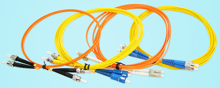
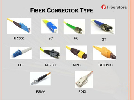
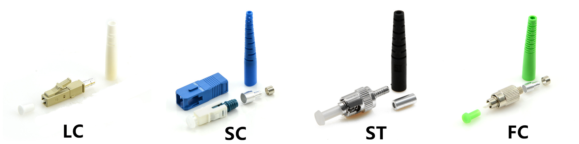
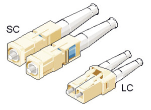
With the rapid development of fiber networks, fiber connectors have become an essential assembly to cater for high-performance fiber optic system. There are various fiber connector types in the market, such as LC, ST, SC, MPO/MTP and so on, among which, SC is one of the most commonly used fiber connectors. Further Classifying SC by polishing type, we have SC APC connector and SC UPC connector. This article will introduce SC APC vs SC UPC and illustrate their difference for your selection guide.

SC APC vs SC UPC: What Refers to SC?

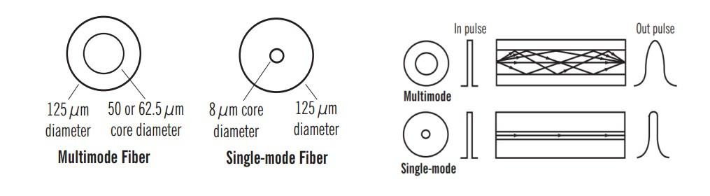
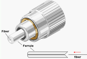
SC is the abbreviation of Subscriber Connector, sometimes also refers to Square Connector or Standard Connector. SC is a type of fiber optic connector with snap (push-pull coupling) coupling type and a 2.5 mm diameter ferrule, which is popularly used in single mode duplex system for its high performance and accurate alignment.

SC APC vs SC UPC: What Refers to APC and UPC?

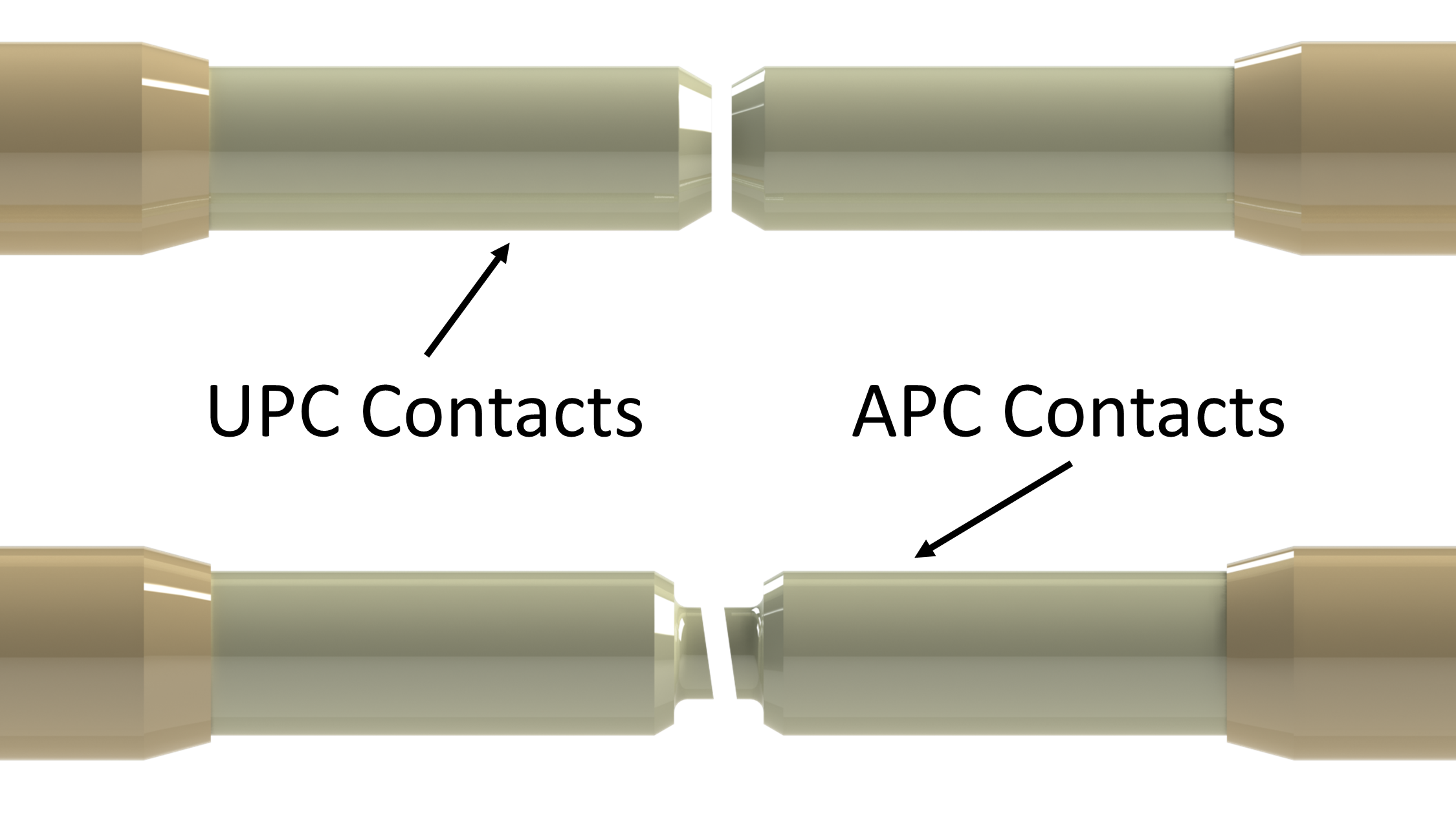
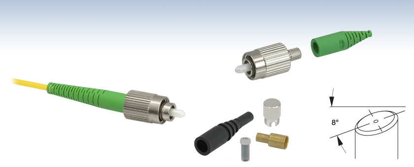
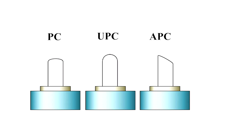
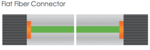
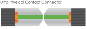
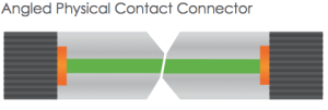
Generally speaking, SC APC connector and SC UPC connector are distinct from each other based on fiber end face. SC APC connector is polished with an 8-degree angle, while SC UPC connector is polished with no angle, which causes difference in light reflection. SC UPC connector adopts an extended polish method to realize finer fiber surface finish, which brings much lower back reflection (ORL) and thus provides much more reliable signal in data center, digital TV and telephone. Although SC UPC connector has low insertion loss and wide range of application, there are some applications requiring for higher return loss, no less than 60 dB or even higher. In this circumstance, SC APC connector can make the need and consistently perform well due to the 8-degree angle.

SC APC

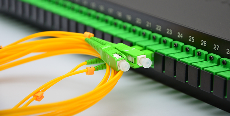
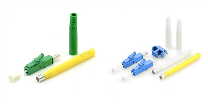
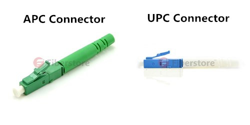
Figure 1: This photo shows a SC APC connector.

SC APC vs SC UPC: What Are the Differences?

As mentioned above, we know SC APC and SC UPC varies from polishing style, which is a difference in the manufacturing process. But in the actual usage, what are the distinct features of SC APC and SC UPC connectors and how to choose from them? Here are some clues.

·Return Loss Value

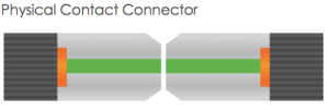
With a SC UPC connector installed on the end of a fiber, reflected light is reflected straight back to the light source. However, with a SC APC connector, reflected light is reflected at an angle into the outer cladding layer rather than straight back towards the light source. This different way of reflection of reflected lights brings about different return loss value. SC APC connector is standardized with a return loss value as -60dB or higher, while SC UPC connector as -50dB or higher.

·Insertion Loss Value

Another specification to consider about fiber connector is insertion loss. Lower the insertion loss, better the performance. Someone prefer SC UPC connector, because they hold the view that SC UPC connector is easier to realize low insertion. This is true on account of less air gaps in SC UPC connector than SC APC connector. However, modern technique has made insertion loss value of SC APC connector as low as SC UPC connector.

·Applications

SC APC connector is commonly used in applications that are much more sensitive to return loss, and requires for high precision signal, such as FTTX (Fiber To The X), video delivery through RF signal, WDM (wavelength division multiplexing) applications and analogue equipment like CCTV. For applications less sensitive to return loss and no other particular demands are required, a SC UPC connector can work as equal effectively as a SC APC connector.

SC UPC

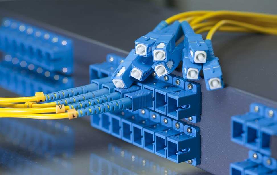
Figure 2: This photo shows a SC UPC connector.

·Other Reference

While SC APC connector is green, SC UPC connector is blue. Besides, the first is much more expensive than the latter one for the optical performance of SC APC much better than SC UPC connector. Other factors to think is the ease of use and your personal needs.

Conclusion

This article touches the concept of several items: SC, APC connector and UPC connector. Then it explains why SC APC connector is distinct from SC UPC connector from several aspects. It is improper to say one SC connector type wins the other for there are lots of consideration under specific circumstances. Simply put, people choose from these two SC connectors according to their personal need. Taking the factors of optical performance, cost and application in usage into consideration, one can make the best choice.

How to Select The Perfect Fiber Jumper Cables?

Fiber jumper cables are mainly used for connection in the context of optical fiber communications including applications like cable TV (CATV), inside buildings and in fiber to the home (FTTH) installations. Nowadays, optical fiber jumpers are varied in cables and connector types. It is hard to determine the differences between one fiber optic cable jumper and another. This article would put emphasis on guiding you to select the perfect fiber jumper cables from the following six perspectives.

fiber-patch-cords

Cable Type of Fiber Jumper Cables

Fiber jumper cables comes in two general types, singlemode and multimode optical fiber jumper. They are different in fiber diameter, classifications of fiber strands, jacket color, transmission speed and etc.

Singlemode fiber jumper cable generally has a 9 micron diameter glass fiber. There are two sub groups (referred to as OS1 and OS2) but most cable is “dual rated” to cover both classifications. Multimode optical fiber jumper can have several different diameters and classifications of fiber strands. The two diameters currently in use are 62.5 Micron and 50 Micron. Within the 50 Micron diameter multimode cable, there are three different grades (referred to as OM2, OM3, and OM4). The cable types used in the patch cord should match that of the network cabling to which they are attached via the patch panel.

Jacket Diameters

The fiber optic cable jumpers may be available in different “jacket diameters” (such as 2mm or 3mm). Thinner diameters (1.6 or 2mm) may be preferable in dense installation within a single rack since they take up less space and are more flexible. Fiber optic cable jumpers that route from rack to rack (especially via cable tray) may be more suitable if they have the thicker jacket that results in larger diameters thus making them more rigid.

Jacket Material

Flammability of the jacket material could become an issue if the area they are in has special requirements for flame spread or products of combustion in case of a fire. In these cases, optical jumpers may have to be classified as “Plenum Rated” (OFNP) rather than “Riser Rated” (OFNR).

Connector Type

See the connector type descriptions below. Some fiber jumper cables may have different connector types on each end to accommodate interconnection of devices with dissimilar connectors. In some cases, there may be a connector on only one end, and bare or unterminated fiber on the other. These are usually referred to as “pigtails” rather than “patch Cords”.

fiber-optic-connector

Simplex or Duplex

Unlike copper patch cords which send information in both directions (having multiple pairs of conductors with which to do so), most fiber jumper cables have a single strand of fiber allowing for signal flow in one direction only.

Connecting equipment so that it can send and receive information requires two strands of fiber (one to transmit and one to receive information). This can be accommodated by using two “simplex” (single strand of fiber) cables for each equipment interconnection or a “duplex” cable, with conductors and/or connectors bonded together in pairs.

Length

Overall length of the fiber jumper cables may be specified in feet or meters, depending on your preference.

Conclusion

In this article, we mainly introduce six factors attaching to the fiber jumper cables—cable type, jacket diameters, jacket material, connector type, type of communication service as well as the length. You can select the proper patch cord you need through considering those six attributes. Hope this post is helpful for you to fully understand optical fiber jumper.

How to Terminate Bare Fiber With Fiber Optic Connector?

There are usually two ways for fiber optic termination. Bare optic fiber can be either spliced with another fiber for a permanent joint or connected with fiber optic connector for a temporary joint. When using the fiber optic connector, we can easily install or uninstall the cable for various applications. This type of termination is more flexible and simple to operate. It is also time-saving to use fiber optic connectors for cable connectivity. However, do you know the right process to terminate bare fiber with fiber optic connector? This article will guide you step by step.

Common Fiber Optic Connectors

Let’s start from the fiber optic connectors. Choosing the right kind of connector for your termination is extremely important. In today’s market, four types of fiber optic connectors are widely used for terminating single fibers. They are LC, SC, ST and FC connectors. LC connector has a 1.25mm ceramic ferrule which is only half the size of other connectors. It’s a snap-in connector usually used for high-density applications. SC connector uses a 2.5mm ceramic ferrule and also features a snap-in connection for quick cable patching. Different from other connectors, ST connector uses a bayonet twist-lock connection with 2.5mm ferrule. Moreover, FC is a screw type connector with 2.5mm ferrule but is becoming less popular than LC and SC connectors.

common-fiber-optic-connector

Connector Polish Styles

When terminating the optic fiber with connector, you should also decide the polish type if the connector is not polished in advance. Generally, connector end face will be polished to minimize back reflection of light. Using the mated polish styles, light can propagate through connectors with lower fiber loss. There are four types of polish styles – flat, PC, UPC and APC polishes. Among them, UPC and APC types are more popular in the industry. The major difference between UPC and APC connectors is that the APC type is polished at an 8-degree angle while UPC has no angle, but they are both slightly curved for better core alignment. As for the color, UPC connector is usually blue and APC connector is green.

upc-apc-polish

Important Precautions

Fiber optic cable is very fragile and sensitive to contamination, thus we need to pay more attention to the precautions before starting termination. Here lists some general precautions as a reference:

  • Always keep dust cap on unused connectors. Store spare dust caps in a dust free environment.
  • Remember to clean the connector and fiber before termination.
  • Make sure there is no laser light in the fiber during termination process.
  • Do not bend the optic fiber at a radius less than 25 mm.
Termination Process

When everything is ready, we can begin the fiber optic termination. The followings are the specific steps.

  • Step 1, measure and mark the cable jacket to the desired length(usually 35 mm). Place jacket stripper on mark and squeeze gently until cutter closes. Pull the cut section off the cable.
  • Step 2, measure and mark kevlar to the desired length(usually remain 7 mm). Use scissors to cut away extra kevlar.
  • Step 3, measure and mark the buffer to the desired length(usually remain 16 mm). Strip the buffer in several small lengths to avoid fiber damage.
  • Step 4, use a lint-free, alcohol-soaked tissue to clean the fiber.
  • Step 5, fill the syringe with adhesive, and slowly inject the adhesive into the ceramic tip.
  • Step 6, gently insert the fiber into the connector and put the connector components together.
  • Step 7, place the connector in the polishing disk. Put it on the polishing film, and lightly polish the connector for 8 to 10 times.
  • Step 8, mission complete! Give it a try on your equipment.

fiber-optic-termination

Conclusion

Bare fiber terminated with fiber optic connectors greatly eases the stress for cable installation. It is always recommended to turn to the professionals for help when doing fiber optic termination.

An Easy Guide to MPO/MTP Polarity

Nowadays, many data centers are migrating into the 40G and 100G transmission. To prepare for this change, MPO/MTP technology is applied to meet the requirements of high density patching. Typically, a fiber optic link needs two fibers for full duplex communications. Thus the equipment on the link should be connected properly at each end. However, high density connectivity usually requires more than two fibers in a link, which makes it more complex to maintain the correct polarity across a fiber network, especially when using multi-fiber MPO/MTP components for high data rate transmission. Therefore, many technicians would prefer to use pre-terminated MPO/MTP components designed with polarity maintenance for easier installation. This article will specifically guide you to understand the polarity of MPO/MTP products and the common polarization connectivity solutions.

What Is Polarity?

Keeping the right polarity is essential to the network. A transmit signal from any type of active equipment will be directed to the receive port of a second piece of active equipment and vice versa. Polarity is the term used in the TIA-568 standard to explain how to make sure each transmitter is correctly connected to a receiver on the other end of a multi-fiber cable. Once the component is connected to the wrong polarity, the transmission process will be unable to go on.

Structure of MPO/MTP Connector

When discussing about the polarity, MPO/MTP connector is an important component for you to know. An MPO/MTP connector has a key on one side of the connector body. There are two positions of the key – key up or key down. Key up position means that the key sits on top. When the key sits on the bottom, it is the key down position. Moreover, the fiber holes in the connector are numbered in sequence from left to right named as P1 (position 1), P2, etc. Each connector is additionally marked with a white dot on the connector body to designate the P1 side of the connector when it is plugged in. The MPO/MTP connector can be further divided into female connector and male connector. The former has no pins while the latter has two pins on the connector. The following picture shows the basic structure of MPO/MTP connector.

structure-of-mpo-connector

Connecting Methods of A, B, C

The TIA standard defines two types of duplex fiber patch cables terminated with LC or SC connectors to complete an end-to-end fiber duplex connection: A-to-A type patch cable is a cross version and A-to-B type patch cable is a straight-through version. Based on this, there are three polarity connecting methods for MPO/MTP products. Here will introduce them in details.

duplex-patch-cable

Method A is the most straight-forward method. It uses straight-through patch cords (A-to-B) on one end that connect through a cassette (LC-to-MPO or SC-to-MPO depends on what the equipment connector is), a straight-through MPO/MTP key up to key down backbone cable and a “cross-over” patch cord (A-to-A) at the other end.

method-a

Method B is the “cross-over” occurred in the cassette. The keys on the MPO cable connectors are in an up position at both ends, but the fiber that is at connector P1 in one end is in P12 at the opposite end, and the fiber that is in P12 at the originating end is in P1 at the opposing end. Only A-to-B type patch cord is needed for this method.

method-b

Method C is the most complicated. There is pair-wise “cross-over” in the backbone cable. A-to-B patch cords are used on both ends. The cassette uses MPO/MTP key up to key down and the backbone cable is pair-wise flipped so P1, P2 connects to P2, P1 and P3, P4 connects to P4, P3, etc.

method-c

Conclusion

Knowing the polarity of MPO/MTP system helps you better upgrade the 40G and 100G networks. According to different polarity methods, choosing the right MPO/MTP patch cables , connectors and cassettes will provide greater flexibility and reliability for your high density network.

Fiber Optic Connector Cleaning

With the deployment of 40G and 100G systems in the data center, reliable and efficient fiber installations are critical to the high performance network. Contaminated fiber optic connectors can often lead to degraded performance. Any contamination on the fiber connectors can cause failure of the component or failure of the whole system. So it’s important to keep fiber connectors clean.

Contamination Sources

There are two most important forms of contamination on fiber connectors and they are oils and dust. Oils from human hands will leave a noticeable defect easily seen with a fiberscope. The oil will trap dust against the fiber and bring scratches to the fiber connector. Inserting and removing a fiber can create a small static charge on the ends, which can attract airborne dust particles. Simply removing and re-inserting a fiber may also contaminate the end of the connector with a higher level of dust. Fiber caps, which are used to prevent fiber ends from being contaminated while not seated in a connector, will collect dust, dirt, oil and other contaminants to the fiber when used. Except oil and dust, there also other types of contamination, such as film residues condensed from vapors in the air, powdery coatings leaving after water or other solvents evaporating away. These contaminates tend to more difficult to remove and can also cause damage to equipment if not removed.

Contamination Inspection Tools

To inspect whether a fiber connector is contaminated, one should use fiberscope, clean and resealable container for the endcaps, bulkhead probe. A fiberscope is a customized microscope for inspecting optical fiber components. The fiberscope should provide at least 200x total magnification. The bulkhead probe is a handheld fiberscope used in order to inspect connectors in a bulkhead, backplane, or receptacle port. It should provide at least 200x total magnification displayed on a video monitor.

Contamination Inspection Steps

With contamination inspection tools, you should know how to inspect fiber connectors. The following introduces the inspection steps:

  • Make sure that the lasers are turned off before you begin the inspection. Be careful: Invisible laser radiation might be emitted from disconnected fibers or connectors. Do not stare into beams or view directly with optical instruments.
  • Remove the protective cap and store it in a clean resealable container. Verify the style of connector you inspect and put the appropriate inspection adapter or probe on your equipment.
  • Insert the fiber connector into the fiberscope adapter, and adjust the focus ring so that you see a clear end-face image. Or, place the tip of the handheld probe into the bulkhead connector and adjust the focus.
  • On the video monitor, see if there is contamination present on the connector end-face (See the following figure).

fiber optic connector before and after cleaning

Connector Cleaning Tools

If there is contamination inspected on the fiber connector, then you need to clean it with proper tools. These tools can be divided into four types based on the cleaning method.

one push cleaner

  • Wet cleaning: Optic cleaning with a solvent.
  • Non-Abrasive cleaning: Cleaning without abrasive material touching the fiber optic connector end face.
  • Abrasive cleaning: The popular lint free wipes, such as fiber optic mini foam swabs.
Connector Cleaning Steps

How to clean the fiber connector? Here is about the cleaning steps with abrasive cleaning tools.

  • Gently wipe end-face with lint-free pad in one direction.
  • Using a can with compressed gas held upright and approximately 2 inches from the connector end, release a stream of gas on the connector end-face for no more than 5 seconds.
  • Gently wipe the ferrule and the end-face surface of the connector with an alcohol pad. Making sure the pad makes full contact with the end-face surface. Wait 5 seconds for the surface to dry.

After finishing the cleaning steps, you should better inspect again to make sure there is definitely no contamination on the connector. Remember never touch the end face of the fiber connector and always install dust caps on unplugged fiber optic connectors. Do not re-use optic cleaning swabs or lens paper (lint free wipes).

Source: Fiber Optic Connector Cleaning

How Does Fiber Connector Polish Type Influence Termination?

Connectors are used to mate two fibers to create a temporary joint and/or connect the fiber to a piece of network device. That’s one of fiber termination ways. The primary specification of connector termination is loss or the amount of light lost in the connection. Connector loss can be caused by a number of factors. This article will talk about the influence of fiber connector polish type on connector termination.

fiber-connector-termination

When the cone of light emerges from the connector, it will spill over the core of the receiving fiber and be lost. In addition, the end gaps can arouse the other problem called reflectance. The air gap in the joint between the fibers causes a reflection when the light encounters the change of refractive index from the glass fiber to the air in the gap. This reflection is called to as reflectance or optical return loss, which can be a problem in laser based systems.

Nowadays the fiber optic connectors have several different ferrule shapes or finishes, usually referred to as end finish or polish types. The connector end face preparation will determine the connectors’ return loss, also known as back reflection. Different end face causes different back reflection.

PC Polish

The Physical Contact (PC) polish results in a slightly curved connector surface, forcing the fiber ends of mating connector pairs into physical contact with each other. This eliminates the fiber-to-air interface and results in back reflections of -30 to -40 dB. The PC polish is the most popular connector end face, used in most applications.

UPC Polish

In the Ultra PC (UPC) polish, an extended polishing cycle enhances the surface quality of the connector, resulting in back reflections of -40 to -55 dB and < -55dB, respectively. These polish types are used in high-speed, digital fiber optic transmission systems.

APC Polish

Later, it was determined that polishing the connector ferrules to a convex end face would produce an even better connection. The convex ferrule guaranteed the fiber cores were in contact. Losses were under 0.3dB and reflectance -40 dB or better. This solution is to angle the end of the ferrule 8 degrees to create APC or angled PC connector. Then any reflected light is at an angle that is absorbed in the cladding of the fiber, resulting in reflectance  of >-60 dB.

FC-APC-Connector

As the introduction of fiber optic technology, numerous connector styles have been developed – probably over 100 designs. Each connector style is designed to offer better performance (less light loss and reflectance) and easier, faster and/or more inexpensive termination. For example, FC–“Ferrule Connector”. The following are three common types of FC connectors:

  • FC/PC–It’s the most common of the FC connectors. The tip is slightly curved to ensure only the fiber cores make connection during mating not the ferrules themselves. The return loss is 25-40 dB.
  • FC/UPC–The higher quality polish with rounder edges than FC/PC ensures better core mating. The return loss is 45-50 dB. It can mate with FC/PC connectors.
  • FC/APC–Common in most single mode applications where back reflection is critical to be minimized. Identified by the 8 degree of angle present in the ferrule tip along with a typical green colored strain relief boot. The return loss is 55-70 dB. It can only mate with other FC/APC fibers.

From this article, you can see the connector with APC polish type can provide the best connection. Later when you face many different types of fiber optic connectors, you may take polish type as one of the factors to make your decision.

Article source: http://www.china-cable-suppliers.com/how-does-fiber-connector-polish-type-influence-termination.html

Fiber Optic Cable and Connector Selection

Proper selection of fiber optic cables and connectors for specific uses is becoming more and more important as fiber optic systems become the transmission medium for communications and aircraft applications, and even antenna links. Choices must be made in selecting fiber optic cables and connectors for high-reliability applications. This article provides the knowledge for how to make appropriate selections of fiber optic cable and connector when designing a fiber optic system.

Fiber Optic Cable Selection

To select a fiber optic cable, you have to make choices of both the fiber selection and the cable construction selection.

Fiber Selection

The three major fiber parameters used in selecting the proper fiber for an application are bandwidth, attenuation and core diameter.

Bandwidth: The bandwidth at a specified wavelength represents the highest sinusoidal light modulation frequency that can be transmitted through a length of fiber with an optical signal power loss equal to 50 percent of the zero modulation frequency component. The bandwidth is expressed in megahertz over a kilometer length (MHz/km).

Attenuation: The optical attenuation denotes the amount of optical power lost due to absorption and scattering of optical radiation at a specified wavelength in a length of fiber. It is expressed as an attenuation in decibels of optical power per kilometer (dB/km). The attenuation is determined by launching a narrow spectral band of light into the full length of fiber and measuring the transmitted intensity.

Core Diameter: The fiber core is the central region of an optical fiber whose refractive index is higher than that of the fiber cladding. Various core diameters are available to permit the most efficient coupling of light from commercially available light sources, such as laser diodes. There are two basic fiber types, single-mode and multimode. Single-mode fiber has a core diameter of 8 to 10 microns and is normally used for long distance requirements and high-bandwidth applications. Multimode fiber has a core diameter of 50 or 62.5 microns and is usually used in buildings. The picture below shows single-mode and multimode fiber with different core diameters.

multimode and singlemode fiber

Cable Construction Selection

Another important consideration when specifying optical fiber cable is the cable construction. There are three main types of cable configurations: buffered fiber cable, simplex cable and multichannel cable.

Buffered Fiber Cable: There are two kinds of buffered fiber. The first is a loose buffer tube construction where the fiber is contained in a water-blocked polymer tube that has an inner diameter considerably larger than the fiber itself. The loose buffer tube construction offers lower cable attenuation from a given fiber, and a high level of isolation from external forces. Loose buffer cables are typically used in outdoor applications and can accommodate the changes in external conditions. The second is a tight buffer tube design. A thick buffer coating is placed directly on the fiber. The tight buffer construction permits smaller, lighter weight designs and generally yields a more flexible cable. A comparison of these two cable constructions is shown below.

Buffered Fiber

Simplex Cable: A simplex fiber optic cable has only one tight buffered optical fiber inside the cable jackets. Simplex fiber optic cables are typically categorized as interconnect cables and are used to make interconnections in front of the patch panel. They are designed for production termination where consistency and uniformity are vital for fast and efficient operation.

Multichannel Cable: Building multiple fibers into one cable creates a multichannel cable. This type of cable is usually built with either a central or external strength member and fiber bundled around or within the strength member. An external jacket is used to keep the cable together.

Fiber Optic Connector Selection

Connector is an integral component of the cabling system infrastructure, which keeps the information flowing from cable to cable or cable to device. There are various connector types, including LC, FC, ST, SC, MTRJ, MPO, MTP, DIN, E2000, MU, etc. To design a fiber optic system, optical connector selection is also a very important decision. When selecting an optical connector, you have to take polishing styles, fiber types and number of fibers all into consideration.

Polishing Styles: There are mainly three kinds of polishing styles, PC (physical contact), APC (angled physical contact), and UPC (ultra physical contact). PC, UPC and APC refer to how the ferrule of the fiber optic connectors is polished. PC connector is used in many applications. UPC connectors are often used in digital, CATV, and telephony systems. APC connectors are preferred for CATV and analog systems. The picture below shows these three kinds of polishing styles.

Polish Types

Fiber Types: Single-mode and multi-mode optical fiber are two commonly used fiber types. Accordingly, there are single-mode optical connector and multi-mode optical connector. ST and MTRJ are the popular connectors for multi-mode networks. LC connector and SC connector are widely used in single-mode systems. Single-mode fiber optic connectors can be with PC, or UPC or APC polish, while multi-mode fiber optic connectors only with PC or UPC polish.

Number of Fibers: Simplex connector means only one fiber is terminated in the connector. Simplex connectors include FC, ST, SC, LC, MU and SMA. Duplex connector means two fibers are terminated in the connector. Duplex connectors include SC, LC, MU and MTRJ. Multiple fiber connector means more than two fibers are terminated in the connector. These are usually ribbon fibers with fiber count of 4, 6, 8, 12 and 24. The most popular ribbon fiber connector is MT connector.

Conclusion

The key to designing a successful fiber optic system is understanding the performance and applications of different kinds of fibers, cable constructions and optical connectors, and then utilizing the appropriate components. Fiberstore provides a wide range of fiber optic cables and connectors. Fiber optic cables can be available in single-mode, multimode, or polarization maintaining, and they can meet the strength and flexibility required for today’s fiber interconnect applications.

MPO/MTP Connector – Multi-fiber Connector for High Port Density

In today’s transmission networks, small and multi-fiber connectors are replacing larger, older styles connectors for space saving. For example, the SC connector is gradually being replaced by its small version LC connector which allows more fiber ports per unit of rack space. To save space, multi-fiber connector is also a good solution, like MTP/MPO connectors. MTP/MPO connector allows more fiber ports per unit of rack space and also satisfies parallel optical interconnections’ needs for multi-fiber connection. This article is to introduce MPO/MTP connectors in details.

MPO Connector & MTP Connector

MT ferrule

MPO is short for the industry acronym—”multi-fiber push on”. The MPO connector is a multi-fiber connector which is most commonly defined by two documents: IEC-61754-7 (the commonly sited standard for MPO connectors internationally) and EIA/TIA-604-5 (also known as FOCIS 5, is the most common standard sited for in the US). MPO connectors are based on MT ferrule (showed in the picture on the right) which can provide quick and reliable high performance interconnections up to 4, 12, 24 or more and are usually used with ribbon fiber cables. The following picture shows diagram of MPO connectors, 12-fold (left) and 24-fold (right). The fibers for sending and receiving are colorcoded, red and green, respectively.

mpo-mtp-connector-fiber-count

MTP stands for “Multi-fiber Termination Push-on” connector and it is designed by USConec and built around the MT ferrule. MTP connector is a high performance MPO connector designated for better mechanical and optical performance and is in complete compliance with all MPO connector standards. Some main improvements of MTP connector are as following:

  • The MTP connector housing is removable;
  • The MTP connector offers ferrule float to improve mechanical performance;
  • The MTP connector uses tightly held tolerance stainless steel guide pin tips with an elliptical shape;
  • The MTP connector has a metal pin clamp with features for centering the push spring;
  • The MTP connector spring design maximizes ribbon clearance for twelve fiber and multifiber ribbon applications to prevent fiber damage;
  • The MTP connector is offered with four standard variations of strain relief boots to meet a wide array of applications.
Application of MPO/MTP Connector

As mentioned, MPO/MPT connectors are compatible ribbon fiber connectors. MPO/MTP connectors cannot be field terminated, thus MTP/MPO connector is usually assembled with fiber optic cable. MTP/MPO fiber optic cable is one of the most popular MTP/MPO fiber optic cable assemblies, which are now being widely used in data center to provide quick and reliable operation during signal transmission. MPO/MTP connectors can be found in the following applications:

  • Gigabit Ethernet
  • CATV and Multimedia
  • Active Device Interface
  • Premise installations
  • Optical Switch interframe connections
  • Interconnection for O/E modules
  • Telecommunication Networks
  • Industrial & Medical, etc.
MPO/MTP Connector Selection Guide

The structure of MPO/MTP connector is a little complicated. The picture below shows the components of a MPO connector.

MPO connector components

With the drive of market requests. Various types of MPO/MTP connectors are being provided. Some basic aspects should be considered during the selection of a MPO/MTP connector are as following:

mtp-mpo-connector-male-female

First is pin option. MPO/MTP connectors have male and female design (as showed in the picture on the left). Male connectors have two guide pins and female connectors do not. Alignment between mating ferrules of MPO/MTP connectors is accomplished using two precision guide pins that are pre-installed into the designated male connector. Second is fiber count: MPO/MTP connector could provide 4, 6, 8, 12, 24, 36, 64 or more interconnections, among which 12 and 24 are the most popular MPO/MTP connectors. In addition, like other fiber optic connectors, the selection of a MPO/MTP connectors should also consider fiber type and simplex or duplex design.

MPO/MTP Connector is a popular multi-fiber connector for high port density. It can offer ideal solution to set up high-performance data networks with the advantages of time saving and cost saving. As an important technology during migration to 40/100 Gigabit Ethernet, MTP/MPO connector is now being adopted by more and more data centers.

LC Connector Introduction

Fiber optic connectors are used to the mechanical and optical means for cross connecting fibers. Fiber optic connectors can also be used to join fiber cables to transmitters or receivers. There have been many types of connectors developed for fiber cable. Single mode networks have used FC or SC connectors in about the same proportion as ST and SC in multimode installations. But LC connector with smaller size and higher performance has become popular and the connector choice for optical transceivers for systems operating at gigabit speeds. The following text gives a detailed introduction of LC connector.

History of LC Connector

LC stands for Lucent Connector, as the LC connector was developed by Lucent Technologies as a response to the need by their primary customers, the telcos, for a small, low insertion loss connector. Then the LC design was standardized in EIA/TIA-604-10 and is offered by other manufacturers.

SC connector and LC connector

Advantages of LC Connector

There are solid reasons that the LC is the preferred connector for high-performance network. From the appearance, LC connect is like a mini size of SC connector. LC connector borrows split-sleeve construction and a cylindrical ferrule (usually ceramic) from SC connector. LC connector has a push-and-latch design providing pull-proof stability in system rack mounts. The picture on the right shows the appearance of SC connector and LC connector.

The ferrule size of LC connector is 1.25 mm which is half the size of SC connector ferrule—2.5 mm. LC connector is rated for 500 mating cycles and its typical insertion loss is 0.25 dB. An interesting feature of the LC is that, in some designs, the ferrule can be “tuned” or rotated with a special tool after it has been assembled. This offers a considerable performance advantage. The design and performance of LC connector address the need for high density and low insertion loss.

Application of LC Connector

LC connector can be found in many places for termination and connection, especially SFP transceivers for gigabit transmission. For example, the optic interfaces of Cisco SFP transceivers are all LC connectors. Some other applications are as following:

Simplex and duplex LC connectors

  • Telecommunication networks
  • Local area networks
  • Data processing networks
  • Cable television
  • Fiber-to-the-home
  • Premises distribution
LC Connector Selection Guide

To meet the needs of market, there are various types of LC connectors provided now. During the selection of LC connector, transmission media should be the first factor to consider. LC connector favors single mode fiber optic cable. But it can also be used with multimode fiber optic cable. Signals sometimes are transferred over simplex fiber optic cable and sometime duplex fiber optic cable. Thus, LC connector has both simplex and duplex design. The picture above shows an APC simplex LC connector on the left and a UPC duplex LC connector on the right. Some other factors like polishing style (APC or UPC), hole size and cable diameter should not be ignored. For more details about LC connectors, you can visit Fiberstore which provides various LC connectors with high performance and low price.

Introduction of PC, UPC and APC Connector

When we choosing a LC connectors, you might hear descriptions like LC UPC polished fiber optic connector, or LC APC fiber optic connector. Or when you are choosing a ST fiber optic patch cable, you can find the description like ST/PC multimode fiber optic patch cable. What do PC, UPC, APC stand for? The following text will give the explanations.

fiber optic connector ferrule

PC (physical contact), UPC (ultra physical contact) and APC (angle physical contact) are the polish style of ferrules inside the fiber optic connectors. Unlike copper cables with copper wire in the connectors as connection media, fiber optic connectors are with ceramic ferrules for connection. The picture on the left shows the ferrule in fiber optic connector. Different fiber optic connectors has different ferrule size and length. Also their polish style might be different.

To better understand the why we have PC, UPC and APC, let’s start with the original fiber optic connector which has a flat-surface and is also known as flat connector (showed in the following picture). When two flat fiber connectors are mated, an air gap naturally forms between the two surfaces from small imperfections in the flat surfaces. The back reflection in flat connectors is about -14 dB or roughly 4%. To solve this problem, the PC connectors came into being.

flat fiber connector

In the PC connector, the two fibers meet, as they do with the flat connector, but the end faces are polished to be slightly curved or spherical. This eliminates the air gap and forces the fibers into contact. The back reflection is about -40 dB. The following picture shows two end faces of PC connectors.

PC connector

UPC connector, usually has a blue-colored body, is an improvement to the PC connector with a better surface finish (as showed in the following picture) by an extended polishing. The back reflection of UPC connector is about -55 dB which lower than that of a standard PC connector. UPC connectors are often used in digital, CATV and telephony systems.UPC connector

PC and UPC connectors have reliable, low insertion losses. However, their back reflection depends on the surface finish of the fiber. The better the fiber gain structure, the lower the back reflection. If the PC and UPC connectors are continually mated and remated, back reflection will degrade. An APC connector won’t have such problem. Its back reflection does not degrade with repeated matings.

APC connector

APC connector usually has a green body with an end-face still curved but are angled at an industry-standard 8 degrees (showed in the above picture) which allows for even tight connections and smaller end-face radii. Thus any light that is redirected back towards the source is actually reflected out into the fiber cladding, again by virtue of the 8 degree angled end-face. APC ferrules offer return losses of -65dB. Some applications that are more sensitive to return loss than others that call for APC connectors, like FTTx and Radio Frequency (RF) applications. APC connectors are also commonly used in passive optical applications due to the fact that many of these systems also use RF signals to deliver video.

APC connector and UPC connector

PC, UPC or APC, which should be the choice of fiber optic connector? The answer is it depends. Choosing the appropriate connector for a fiber network depends on things such as, network design and function. Fiberstore offers a wide range of fiber optic connector as well as professional optical network solution. For more information you can visit Fiberstore.

Fiber Optic Connector: An Important Part of Fiber Optic Termination

Fiber optics are used for a variety of applications in the photonics industry. Fiber optics are typically connectorized for convenience of mating and coupling. These connectors come in many configurations and styles. A fiber optic connector that was lower loss, lower cost, easier to terminate or solved some other perceived problem is urgently needed to the industry. As a result, about 100 fiber optic connectors have been introduced to the marketplace, but only a few represent the majority of the market. Today, Fiberstore’s Blog are going to show you these commonly used fiber optic connectors.

fiber optic connector

Fiber Optic Connector Types
Commonly used fiber optic connector types include SC, FC, LC, ST, MU, E2000, MTRJ, SMA , DIN as well as MTP & MPO etc. They are widely used in the termination of fiber optic cables, such as fiber optic pigtail, fiber optic patch cables and so on.

LC connector LC Connector (Lucent Connector) — Ferrule diameter = 1.25mm. LC connectors are licensed by Lucent and incorporate a push-and-latch design providing pull-proof stability in system rack mounts. LC connectors are available in single mode and multimode. Externally LC connectors resemble a standard RJ45 telephone jack. Internally they resemble a miniature version of the SC connector. This type of connectors are commonly used in connecting SFP Transceiver Module in Router/Switch. For example, the optic interfaces of Cisco’s SFP transceivers are all LC connectors.
SC connector SC Connector (Subscriber Connector) — Ferrule diameter = 2.5mm. The SC connector is becoming increasingly popular in single-mode fiber optic telecom and analog CATV, field deployed links. But the most commonly used field is to connect GBIC (100Base-FX) in router/switch. The high-precision, ceramic ferrule construction is optimal for aligning single-mode optical fibers. The connectors’ outer square profile combined with its push-pull coupling mechanism, allow for greater connector packaging density in instruments and patch panels. The keyed outer body prevents rotational sensitivity and fiber endface damage. Multimode versions of this connector are also available. The typical insertion loss of the SC connector is around 0.3 dB.
ST connector ST Connector (Straight Tip) — Ferrule diameter = 2.5mm. ST connector’s high-precision, ceramic ferrule allows its use with both multimode and single-mode fibers. The bayonet style, keyed coupling mechanism featuring push and turn locking of the connector, prevents over tightening and damaging of the fiber end. The insertion loss of the ST connector is less than 0.5 dB, with typical values of 0.3 dB being routinely achieved. ST connector is used extensively both in the field and in indoor fiber optic LAN applications, eg. ODF (optical distribution frame). In addition, ST connector is also used to connect GBIC transceiver, usually for 100Base-F.
FC connector FC Connector (Ferrule Connector) — Ferrule diameter = 2.5mm. The FC has become the connector of choice for single-mode fibers and is mainly used in fiber-optic instruments, SM fiber optic components, and in highspeed fiber optic communication links. This high-precision, ceramic ferrule connector is equipped with an anti-rotation key, reducing fiber endface damage and rotational alignment sensitivity of the fiber. The key is also used for repeatable alignment of fibers in the optimal, minimal-loss position. Multimode versions of this connector are also available. The typical insertion loss of the FC connector is around 0.3 dB.
MU connector MU Connector (Miniature Unit) — Ferrule diameter = 1.25mm. MU is a small form factor SC. It has the same push/pull style, but can fit 2 channels in the same Footprint of a single SC. MU was developed by NTT. It is a popular connector type in Japan. Applications include high-speed data communications, voice networks, telecommunications, and dense wavelength division multiplexing (DWDM). MU connectors are also used in multiple optical connections and as a self-retentive mechanism in backplane applications.
MTRJ connector MTRJ Connector (Mechanical Transfer Registered Jack) — Ferrule diameter = 2.45×4.4 mm. MT-RJ is a duplex connector with both fibers in a single polymer ferrule. It uses pins for alignment and has male and female versions. Multimode only, field terminated only by prepolished/splice method.
E2000 connector E2000 Connector — Ferrule diameter = 2.5mm. E2000 connector is a plastic push-pull connector developed by Diamond. The E2000 was developed as an improvement on the SC connector design by having: a latch that retains the connector, a dust cap always in place, and a smaller size. The built in dust cap always stays on the connector protecting the ferrule and blocking harmful laser light when the connector is disconnected. E2000 is available for Singlemode and Multimode applications.
sma SMA Connector (Sub Miniature A) — Ferrule diameter = 3.14mm. Due to its stainless steel structure and lowprecision threaded fiber locking mechanism, this connector is used mainly in applications requiring the coupling of high-power laser beams into large-core multimode fibers. Typical applications include laser beam delivery systems in medical, bio-medical, and industrial applications. The typical insertion loss of an SMA connector is greater than 1 dB.
DIN connector DIN Connector — Ferrule diameter = 2.5mm. DIN connector is a metal screw on connector which is developed by Siemens. Deutsch Telecom mainly uses it. This is a good connector to use where the ruggedness of a metal screw on connector is required but
where there is not enough space for a FC Connector.
mtp&mpo connector MTP and MPO Connector — MTP and MPO are compatible ribbon fiber connectors based on MT ferrule which allow quick and reliable connections for up to 12 fibers. They are intended for installations that require many fiber connections. Up to 12 fibers in a ribbon are stripped to 125um cladding and inserted into 250um spaced parallel grooves. The ferrule also includes two 0.7mm diameter holes, running parallel to the fibers on the outer side of the ferrule. These two holes hold precision metal guide pins which align the fibers with tight tolerances. MTP and MPO connectors feature male and female connector design. Male connectors have two guide pins and female connectors do not. Both connector types need an adapter to mate a pair of male and female connectors. Because MTP and MPO connectors are trying to align so many fibers at once, their coupling loss are typically bigger than single fiber connectors.


History of Different Connector Types
The ST connector is the oldest design of the connectors still in common use. It was the first connector to use a 2.5mm ferrule. The FC and DIN connectors improved on the ST connector by: isolating cable tension from the ferrule, keying the location of the ferrule for angle polishing, and threading onto the adapter for a more positive connection. The SC connector was then developed to eliminate having to screw and unscrew the connector every time and to reduce the cost by molding instead of machining the connector. A big advantage of this push/pull connector over a FC connector is that less room is required between connectors on patch panels. The E-2000 was developed as an improvement on the SC connector design by having: a latch that retains the connector, a dust cap always in place, and a smaller size. As patch panel densities increased the LC and MU connectors were developed to reduce the space required for connectors on patch panels. Both of these connectors use a 1.25mm ferrule. The MT-RJ connector was then developed to put transmit and receive fibers into one connector. This was the first connector to use the MT ferrule design as opposed to a 2.5mm or 1.25mm diameter ferrule. The MTP connector was then developed to increase fiber density even more. The MTP currently has 12 fibers in its MT ferrule however a 24-fiber version is under development.

There are many more influences that lead to the development of these different commonly used connector types. This is why all of the different connector types exist. In fact, there are not only these connector types. A multitude of specialty connectors are launched to the market for different application.

Connector Endface Preparation
Once the optical fiber is terminated with a particular connector, the connector endface preparation will determine what the connector return loss, also known as back reflection, will be. The back reflection is the ratio between the light propagating through the connector in the forward direction and the light reflected back into the light source by the connector surface. Minimizing back reflection is of great importance in high-speed and analog fiber optic links, utilizing narrow line width sources such as DFB lasers, which are prone to mode hopping and fluctuations in their output.

polishing type

Flat Polish — a flat polish of the connector surface will result in a back reflection of about -16 dB (4%).
PC Polish — the Physical Contact (PC) polish results in a slightly curved connector surface, forcing the fiber ends of mating connector pairs into physical contact with each other. This eliminates the fiber-to-air interface, there by resulting in back reflections of -30 to -40 dB. The PC polish is the most popular connector endface preparation, used in most applications.
UPC/SPC Polish — in the Super PC (SPC) and Ultra PC (UPC) polish, an extended polishing cycle enhances the surface quality of the connector, resulting in back reflections of -40 to -55 dB and < -55dB, respectively. These polish types are used in high-speed, digital fiber optic transmission systems.
APC Polish — the Angled PC (APC) polish, adds an 8 degree angle to the connector endface. Back reflections of <-60 dB can routinely be accomplished with this polish.

Article Source: http://www.fs.com/blog/fiber-optic-connector-an-important-part-of-fiber-optic-termination.html