PLC Splitter for Various Applications

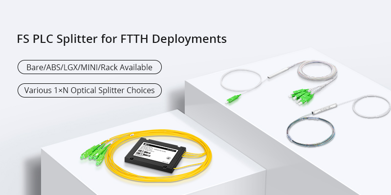
PLC splitter or planar lightwave circuit splitter is a passive component that has the special waveguide made of planar silica, quartz or other materials. It is employed to split a strand of optical signal into two or more strands. PLC splitter also has lots of split ratios, and the most common ones are 1:8, 1:16, 1:32, 1:64, 2:8, 2:16, 2:32 and 2:64. Products usually accord with Telcordia GR-1209-CORE, Telcordia GR-1221-CORE.YD/T1117-2001 standards. There are many types of PLC splitters to meet with different needs in OLT and ONT connection and splitting of optical signals over FTTH passive optical networks.

Importance of PLC Splitter

PLC splitter is especially important in FTTH networks, which shares a single PON network with many subscribers. Having no electronics and power in PLC splitter, it is very cost-effective to provide reliable light distribution solutions. Unlike FBT (fused biconical taper) splitter, PLC splitter has a better performance that offers accurate splits with minimal loss in an efficient package. Some typical types are widely used in optical network applications, i.e. bare fiber splitter, blockless splitter, ABS splitter, fan-out splitter, tray type splitter, rack-mount splitter, LGX splitter and mini plug-in type splitter.

Applications of PLC Splitter
 
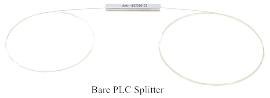
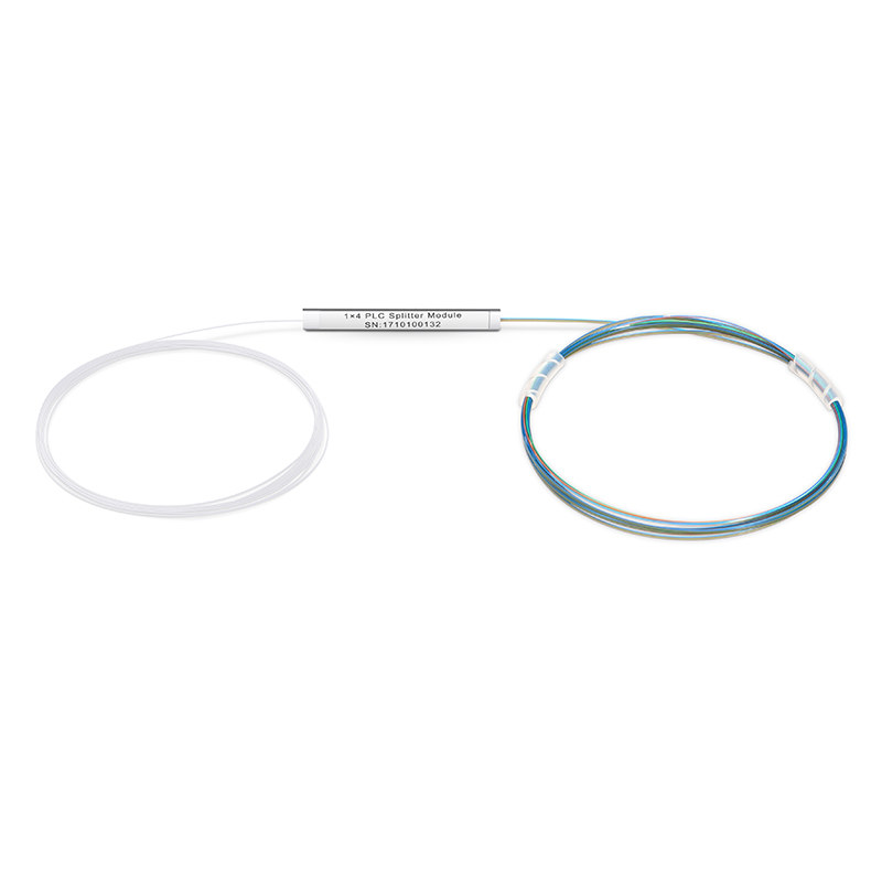
Bare Fiber PLC Splitter

Bare fiber PLC splitter has no connector at the bare fiber ends. It can be spliced with other optical fibers in the pigtail cassette, test instrument and WDM system, which minimizes the space occupation. It is commonly used for FTTH, PON, LAN, CATV, test equipment and other applications.

bare-plc-splitter

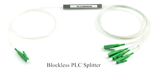
Blockless PLC Splitter

Likewise, blockless PLC splitter has a similar appearance as bare PLC splitter. But it has a more compact stainless tube package which provides stronger fiber protection, and its fiber ends are all terminated with fiber optic connectors. Connectors are commonly available with SC, LC, FC and ST types. Thus, there is no need for fiber splicing during installation. Blockless PLC splitter is mainly used for different connections over distribution boxes or network cabinets.

Blockless-PLC-Splitter

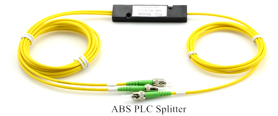
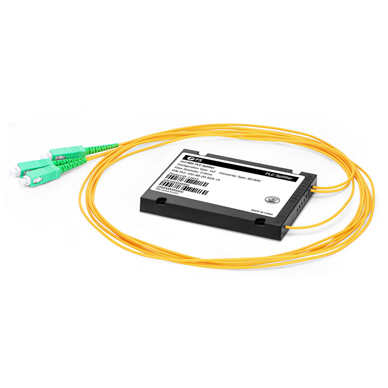
ABS PLC Splitter

ABS PLC splitter has a plastic ABS box to protect the PLC splitter to adapt to different installation environments and requirements. Common splitter modules are 1×4, 1×8, 1×16, 1×32, 1×64, 2×4, 2×8, 2×16, 2×32. It is widely used with outdoor fiber distribution box for PON, FTTH, FTTX, PON, GOPN networks.

ABS-PLC-Splitter

Fanout PLC Splitter

PLC splitter with fan-out is mainly used for 0.9mm optical fiber where the ribbon fiber can convert to 0.9mm optical fiber through fan-out. 1×2, 1×4, 1×8, 1×16, 1×32, 1×64, 2×2, 2×4, 2×8, 2×16, 2×32, 2×64 fanout types are all available with PLC splitters. Fiber adapters can also be used for the input and output ends of this kind of splitters to directly meet the demand on smaller size of splitters.
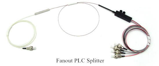
Fanout-PLC-Splitter

Tray Type PLC Splitter

Tray type PLC splitter can be regarded the fiber enclosure which contains PLC fiber splitter inside a enclosure. It is often directly installed in optical fiber distribution box or optical distribution frame. FC, SC, ST & LC connectors are selective for termination. Tray type PLC splitter is an ideal solution for splitting at the places that are near OLT or ONU.
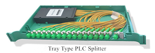
Tray-PLC-Splitter

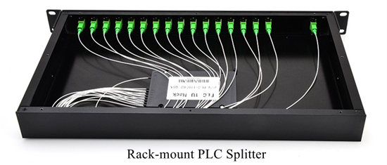
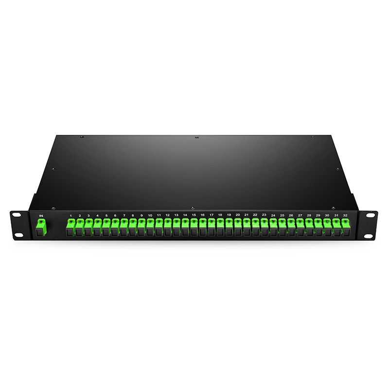
Rack-mount PLC Splitter

Rack-mount PLC splitter can be used for both indoor and outdoor applications in FTTx projects, CATV or data communication centers. It uses the 19-inch rack unit standard to contain the PLC splitter inside a rack unit.

Rack-mount-PLC-Splitter

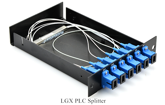
LGX PLC Splitter

LGX PLC splitter or LGX box PLC splitter has a strong metal box to house the PLC splitters. It can be used alone or be easily installed in standard fiber patch panel or fiber enclosure. The standard LGX metal box housing provides a plug-and-play method for integration in the network, which eliminates any risk during installation. No filed splicing or skilled personnel is required during deployment.

LGX-PLC-Splitter

Mini Plug-in Type PLC Splitter

Similar to the LGX PLC splitter, mini plug-in PLC type splitter is its small version with a compact design. It is usually installed in the wall mount FTTH box for fiber optic signal distribution. Using the mini plug-in PLC type splitter saves time and space but still provides reliable protection for the fiber optic splitter.
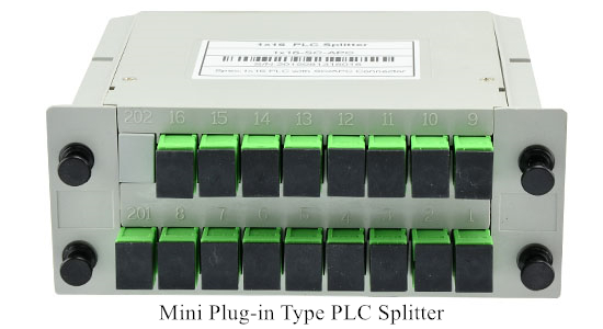
Mini-Plug-in-Type-PLC-Splitter

Conclusion

These types of PLC splitters are typically installed to serve for PON and FTTH networks. 1xN and 2xN are the common splitter ratios for specific applications. You should choose the most suitable one according to your project. Hope this article provides some help.


Source:

How Many Fiber Optic Splitter Types Are There? – FS Community


Introduction of Fiber Optic Sensor

Optical fibers are mainly applied in telecommunications, which has significantly changed this industry. However, there is also a growing application of optical fibers in sensing applications for measurement. Many components associated with optical fibers are developed to sensing applications. One of the most significant components—fiber optic sensor (also known as optical fiber sensor) is now being widely used in sensing applications.

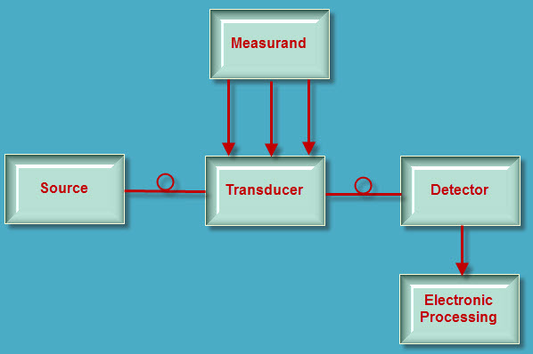
Fiber optic sensors are fiber-based devices to sense some quantities like temperature, pressure, vibrations, displacement, rotations or concentration of chemical species. The basic instrumentation required for sensor are optical source (often a single-frequency fiber laser), sensing element, optical detector and end-prossesing devices (optical-spectrum analyzer, oscilloscope). A block diagram of fiber optic sensor is showed in the following picture.

8-30-2014-10-06-53-AM

Fiber optic sensor offers a wide range of advantages, which makes it being applied in many field successfully. Its advantages are as following.

  • Explosion proof: In fiber optic sensor, the primary signal is an optical. Therefore, there is no risk of spark or fiber.
  • Immunity to electromagnetic interference: Since the fibers are composed of dielectric such as glass. The fiber optic sensor is immune to radio frequency and electromagnetic.
  • Small size, light weight and flexible: This feature extends the applications of fiber optic sensor to many fields, like aircraft.
  • High sensitivity: The optical fiber sensors are highly sensitive and have large bandwidth. When multiplexed into arrays of sensors the large bandwidths of optical fibers themselves offer distinct advantages in their ability to transport the resultant data.
  • Remote sensing: With the availability of low loss optical fibers, the optical signal can be transmitted up to a long distance transmitted up to a long distance (10-1000m). Thus the remote sensing is possible with the optical fiber.
  • Environmental ruggedness and resistant: The optical fiber are manufactured from non-rusting materials such as plastics or glasses, therefore, the fibers have excellent stability when in permanent contact with electrolyte solutions, ionizing radiation etc. Further the fibers can withstand high temperature as high as 350 ca. Special fibers can extend sensor operation beyond 350c to as high as 1200c.
  • Compactness: With the availability of solid-state configurations (small size sources and detectors) it is possible to design a compact optical fiber sensor system.

Based on the sensor location, the fiber optic sensors are generally classified into two types, namely intrinsic and extrinsic fiber optic sensor.

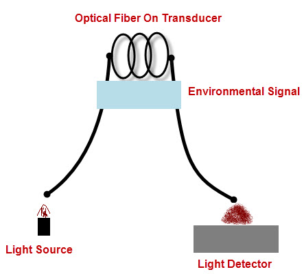
Intrinsic fiber optic sensor can provide distributed sensing over very large distances, which is the most useful feature of it. In intrinsic fiber optic sensor, sensing takes place within the fiber itself. Only a simple source and detector are required. This sensor depends on the properties of the optical fiber itself to convert an environmental action into a modulation of the light beam passing through it. The basic concept of the intrinsic fiber optic sensor is showed in the picture below.

Intrinsic fiber optic sensor

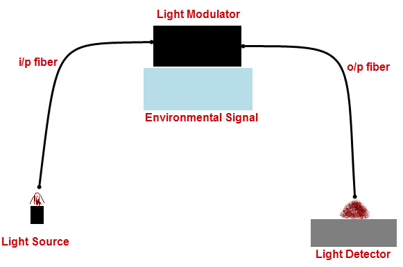
Extrinsic fiber optic sensors use an optical fiber cable, normally a multimode one, to transmit modulated light from either a non-fiber optical sensor, or an electronic sensor connected to an optical transmitter. In this sensor, the fiber may be used as information carriers that show the way to a black box. It generates a light signal depending on the information arrived at the black box. The black box may be made of mirrors, gas or any other mechanisms that generates an optical signal. These sensors are used to measure rotation, vibration velocity, displacement, twisting, torque and acceleration. The major benefit of these sensors is their ability to reach places which are otherwise unreachable. The best example of this sensor is the inside temperature measurement of the aircraft jet engine. The following picture shows the basic concept of the extrinsic fiber optic sensor.

Extrinsic fiber optic sensors

Fiberstore offers fiber optic sensors of high quality. For more information about fiber optic sensor, you can visit its online shop.

Advanced Optical Components – Optical Attenuator

What is Optical Attenuator?

Optical Attenuator (or fiber optic attenuator) is a passive device that is used to reduce the power level of an optical signal. The attenuator circuit allows a known source of power to be reduced by a predetermined factor, which is usually expressed as decibels (dB). Optical attenuators are generally used in single-mode long-haul applications to prevent optical overload at the receiver.

Principles of Optical Attenuators

Optical attenuators use several different principles in order to accomplish the desired power reduction. Attenuators may use the Gap-Loss, Absorptive, or Reflective technique to achieve the desired signal loss. The types of attenuators generally used are fixed, stepwise variable, and continuously variable.

Gap-Loss Principle

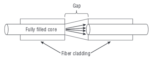
The principle of gap-loss is used in optical attenuators to reduce the optical power level by inserting the device in the fiber path using an in-line configuration. Gap-loss attenuators are used to prevent the saturation of the receiver and are placed close to the transmitter. They use a longitudinal gap between two optical fibers so that the optical signal passed from one optical fiber to another is attenuated. This principle allows the light from the transmitting optical fiber to spread out as it leaves the optical fiber. When the light gets to the receiving optical fiber, some of the light will be lost in the cladding because of gap and the spreading that has occurred. The gap-loss principle is shown in the figure below.

Gap-Loss Principle

The gap-loss attenuator will only induce an accurate reduction of power when placed directly after the transmitter. These attenuators are very sensitive to modal distribution ahead of the transmitter, which is another reason for keeping the device close to the transmitter to keep the loss at the desired level. The farther away the gap-loss attenuator is placed from the transmitter, the less effective the attenuator is, and the desired loss will not be obtained. To attenuate a signal farther down the fiber path, an optical attenuator using absorptive or reflective techniques should be used.

Note: The air gap will produce a Fresnel reflection, which could cause a problem for the transmitter.

Absorptive Principle

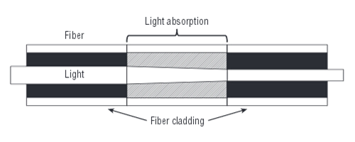
The absorptive principle, or absorption, accounts for a percentage of power loss in optical fiber. This loss is realized because of imperfections in the optical fiber that absorb optical energy and convert it to heat. This principle can be employed in the design of an optical attenuator to insert a known reduction of power.

The absorptive principle uses the material in the optical path to absorb optical energy. The principle is simple, but can be an effective way to reduce the power being transmitted and/or received. Here is the principle of the absorption of light.

Absorptive Principle

Reflective Principle

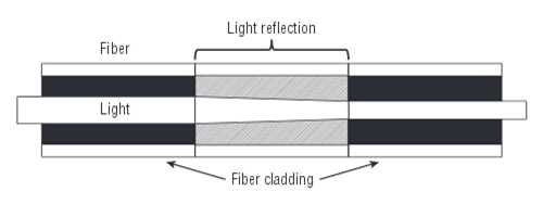
The reflective principle, or scattering, accounts for the majority of power loss in optical fiber and again is due to imperfections in the optical fiber, which in this case cause the signal to scatter. The scattered light causes interference in the optical fiber, thereby reducing the amount of transmitted and/or received light. This principle can be employed in the planned attenuation of a signal. The material used in the attenuator is manufactured to reflect a known quantity of the signal, thus allowing only the desired portion of the signal to be propagated. This reflective principle is shown in the figure below.

Reflective Principle

Types of Optical Attenuators

>>According to the principles behind the attenuator theories, there are three types of optical attenuators: Fixed Attenuator, Stepwise Variable Attenuator, and Continuously Variable Attenuator.

Fixed Attenuator

Fixed Attenuators are designed to have an unchanging level of attenuation. They can theoretically be designed to provide any amount of attenuation that is desired. The output signal is attenuated relative to the input signal. Fixed attenuators are typically used for single-mode applications.

Stepwise Variable Attenuator

A stepwise variable attenuator is a device that changes the attenuation of the signal in known steps such as 0.1 dB, 0.5 dB, or 1 dB. These attenuators may be used in applications dealing with multiple optical power sources. For example, if there are three inputs available, there may be a need to attenuate the signal at a different level for each of the inputs. Conversely, they may also be used in situations where the input signal is steady, yet the output requirements change depending on the device that the signal is output to. Note: The stepwise variable attenuators should be used in applications where the inputs, outputs, and operational configurations are known.

Continuously Variable Attenuator

A continuously variable attenuator is an optical attenuator that can be changed on demand. It generally has a device in place that allows the attenuation of the signal to change as required. Continuously variable attenuators are used in uncontrolled environments where the input characteristics and/or output need continually change. This allows the operator to adjust the attenuators to accommodate the changes required quickly and precisely without any interruption to the circuit.

Note: Both the stepwise variable attenuator and continuously variable attenuator are collectively known as Variable Optical Attenuator (VOA). When people talk about the VOA attenuator, it generally means a continuously variable optical attenuator.

>>According to the different connector types, there are several types of optical attenuators: LC attenuator, SC attenuator, ST attenuator, FC attenuator, E2000 attenuator etc., available in UPC/APC polish types.

Packaging of Optical Attenuators

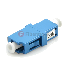
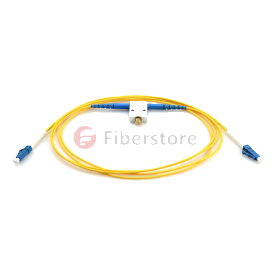
Optical attenuators typically come in two forms of packaging: bulkhead attenuator and in-line attenuator. The bulkhead optical attenuators can be plugged into the receiver receptacle. The in-line optical attenuators resemble a fiber patch cord and is typically used between the patch panel and the receiver. Here are a 10 dB Fixed LC/UPC Bulkhead Optical Attenuator and a 0~60 dB LC/UPC to LC/UPC In-Line Variable Optical Attenuator from Fiberstore.

10 dB Fixed LC/UPC Bulkhead Optical Attenuator 0~60 dB LC/UPC to LC/UPC In-Line Variable Optical Attenuator