OM3 And OM4 Fiber for 10G/40G/100G Network

Multimode fiber has been highly favored by Ethernet users and gained the widest acceptance in network backbones where it has offered users the opportunity to extend link distances, increase network reliability, and lower costs by centralizing electronics. OM3 fiber emerges just at the right time. The predominance of OM3 fiber is that utilizes laser-optimized fiber, which is the highest-capacity medium for short-wave 10G optical transmission. OM4 fiber just joined multimode fiber family after OM3 fiber in order to meet the requirement of longer range applications. This passage would give a brief introduction to OM3 and OM4 fiber, give a further analysis on their differences and selection guide, as well as list their applications.

Introduction to OM3 & OM4 Fiber

Both OM3 and OM4 fiber meet the ISO 11801 standard. The standard specifies that OM3 fibers are capable of 10 Gb/s performance over distances of up to 300m. Like being mentioned, the laser optimized 50/125 mm multimode OM3 fiber is of predominance, which provides sufficient bandwidth to support 10 GbE and beyond with cable lengths up to 550 meters. OM4 fiber is a further improvement to OM3 fiber. It also uses a 50µm core but it supports 10 Gigabit Ethernet at lengths up 550 meters and it supports 100 Gigabit Ethernet at lengths up to 150 meters.

OM4 fiber cable

Main Difference Between OM3 And OM4 Fiber

—Optical attenuation

Attenuation is caused by losses in light through the passive components, such as cables, cable splices, and connectors. Attenuation is the reduction in power of the light signal as it is transmitted (dB). The maximum attenuation of OM3 and OM4 fiber allowed at 850nm: OM3<3.5 dB/Km; OM4 <3.0 dB/Km. So it is obvious that OM4 fiber causes lower losses due to different construction.

—Modal dispersion

As is known to most people, modal dispersion attaches great importance to bandwidth. The lower the modal dispersion, the higher the modal bandwidth and the greater the amount of information that can be transmitted. The minimum OM3 and OM4 fiber cable bandwidth at 850nm: OM3 2000 MHz·km; OM4 4700 MHz· km. The higher bandwidth available in OM4 means a smaller modal dispersion and thus allows the cable links to be longer or allows for higher losses through more mated connectors.

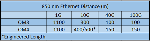
OM3 And OM4 Fiber 10G/40G/100G Transmission Distance

The maximum transmission distance of OM4 fiber is 400-550m (depending on module capability) while OM3 fiber can only be up to 300m. And thus, OM4 can tolerate a higher level of loss at distances between 200-300m as it is designed to operate at longer distances than OM3 fiber. It may be a more flexible option for network managers to install OM4 fiber within these instances. You can check difference between OM3 and OM4 in transmission distance in the following table.

OM3 and OM4 fiber cable distance

OM3 And OM4 Fiber Price

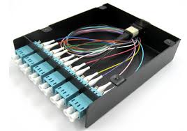
In comparison to OM3 fiber, the cost for OM4 is higher due to the manufacture process and market fluctuations. In a large extent, cost depends on the construction type of the cable (loose tube, tight buffered, etc.). OM4 fiber cable is about twice as expensive as OM3 fiber cable. This means that the cost difference of lots of fiber products such as standard fiber patch panels, MTP cassette modules, fiber patch cords is very small (as the volume of cable is small).

OM3 And OM4 Fiber Selection Guide

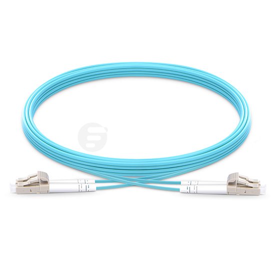
Fifty micron OM3 fiber is designed to accommodate 10 Gigabit Ethernet up to 300 meters, and OM4 can accommodate it up to 550 meters. Therefore, many users are now choosing OM3 and OM4 over the other glass types. In fact, nearly 80% of 50 micron fiber sold is OM3 or OM4. If you require higher data rates or plan on upgrading your network in the near future, laser optimized 50 micron (OM3 or OM4) would be the logical choice. Compared to OM4, OM3 fiber is more future proofing for most applications, which allows speeds of 10 GB/s up to 100 GB/s. OM4 fiber provides users a transmission solution over longer distances and leaves more wiggle room in optical budgets.

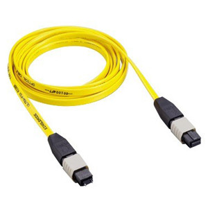
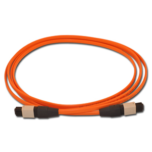
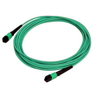
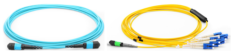
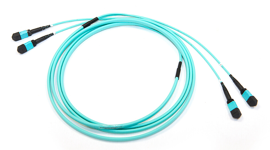
OM3 and OM4 fiber cables are typically used in data center structured cabling environments running high speeds of 10G or even 40 or 100 Gigabit Ethernet, SAN (Storage Area Networking), Fiber Channel, FCOE (Fiber Channel Over Ethernet) with such manufacturers as Cisco, Brocade, EMC and others. Typical applications could be virtualized or internal cloud core data center applications. For 40G and 100G fiber cable applications, MTP/MPO cable would also be a great choice. MTP cabling assemblies (MTP/MPO trunk cable, MTP/MPO harness cable, MTP/MPO conversion cable, etc), with their overwhelming advantages, providing a fast, simple and economical upgrade path from 10 Gigabit to 40 or 100 Gigabit applications.

Conclusion

In this article, we mainly discussed OM3 fiber, OM4 fiber, their main differences, transmission guide and applications for 10G/40G/100G network. We put emphasis on OM3 and OM4 fiber 10G/40G/100G transmission distance and selection guide. OM3 and OM4 multimode fiber provide a cost effective solution for inside buildings or corporate campuses. Hope this article would be helpful for you to understand OM3 and OM4 fiber and to select right fiber cable for yourself.

How to Select The Perfect Fiber Jumper Cables?

Fiber jumper cables are mainly used for connection in the context of optical fiber communications including applications like cable TV (CATV), inside buildings and in fiber to the home (FTTH) installations. Nowadays, optical fiber jumpers are varied in cables and connector types. It is hard to determine the differences between one fiber optic cable jumper and another. This article would put emphasis on guiding you to select the perfect fiber jumper cables from the following six perspectives.

fiber-patch-cords

Cable Type of Fiber Jumper Cables

Fiber jumper cables comes in two general types, singlemode and multimode optical fiber jumper. They are different in fiber diameter, classifications of fiber strands, jacket color, transmission speed and etc.

Singlemode fiber jumper cable generally has a 9 micron diameter glass fiber. There are two sub groups (referred to as OS1 and OS2) but most cable is “dual rated” to cover both classifications. Multimode optical fiber jumper can have several different diameters and classifications of fiber strands. The two diameters currently in use are 62.5 Micron and 50 Micron. Within the 50 Micron diameter multimode cable, there are three different grades (referred to as OM2, OM3, and OM4). The cable types used in the patch cord should match that of the network cabling to which they are attached via the patch panel.

Jacket Diameters

The fiber optic cable jumpers may be available in different “jacket diameters” (such as 2mm or 3mm). Thinner diameters (1.6 or 2mm) may be preferable in dense installation within a single rack since they take up less space and are more flexible. Fiber optic cable jumpers that route from rack to rack (especially via cable tray) may be more suitable if they have the thicker jacket that results in larger diameters thus making them more rigid.

Jacket Material

Flammability of the jacket material could become an issue if the area they are in has special requirements for flame spread or products of combustion in case of a fire. In these cases, optical jumpers may have to be classified as “Plenum Rated” (OFNP) rather than “Riser Rated” (OFNR).

Connector Type

See the connector type descriptions below. Some fiber jumper cables may have different connector types on each end to accommodate interconnection of devices with dissimilar connectors. In some cases, there may be a connector on only one end, and bare or unterminated fiber on the other. These are usually referred to as “pigtails” rather than “patch Cords”.

fiber-optic-connector

Simplex or Duplex

Unlike copper patch cords which send information in both directions (having multiple pairs of conductors with which to do so), most fiber jumper cables have a single strand of fiber allowing for signal flow in one direction only.

Connecting equipment so that it can send and receive information requires two strands of fiber (one to transmit and one to receive information). This can be accommodated by using two “simplex” (single strand of fiber) cables for each equipment interconnection or a “duplex” cable, with conductors and/or connectors bonded together in pairs.

Length

Overall length of the fiber jumper cables may be specified in feet or meters, depending on your preference.

Conclusion

In this article, we mainly introduce six factors attaching to the fiber jumper cables—cable type, jacket diameters, jacket material, connector type, type of communication service as well as the length. You can select the proper patch cord you need through considering those six attributes. Hope this post is helpful for you to fully understand optical fiber jumper.

How to Select Fiber Optic Cables of High Quality?

With the growing numbers of fiber optic patch cord manufacturers, it is difficult to distinguish the quality of fiber optic cables. Poor fiber jumpers could result in many adverse consequences, such as data loss, signal delay and etc. When selecting fiber optic cables, you should pay much attention to the trap of the low price so as to avoid picking up production made by recovered materials. In this article, we would introduce some detailed process to guide you to make right decision for selecting decent fiber optic cables.

About Fiber Optic Cable

Fiber optic cable, also called fiber optic jumper or fiber optic patch cord, is a length of fiber cabling fitted with LC, SC, FC, E2000, DIN, MTRJ or ST connectors at each end. Ferrule is paramount to fiber, which is a ring or cap attached to an object to protect against damage, splitting, or wear. As an essential component in fiber optic, it is used to align and protect the stripped end of a fiber.

fiber optic cable

Manufacturing Process of Fiber Optic Cable

Place of origin attaches great importance to any products, so does the fiber optic cable. Besides the origin, method of manufacture also matters. The production process of fiber optic patch codes is very complicated unless you master it very well. Following is the production process of fiber optic patch cords.

Step1: Pretreatment of fiber optic. Peel fibers by using technical instrument, the main propose of it is to peel the fiber jacket.

Step2: Installment of Fiber ferrule. Fiber ferrule is an important part of fiber optic patch cables, so when installing fiber ferrule, the quality of it should be concerned.

Step3: Preparation of grouting glue.Get the glue ready since fiber stub need to be grouted later. Gel injection of fiber ferrule. The standard of a good gel injection is that a little glue can be seen at the front end of fiber ferrule.

Step4: Solidification of colloid. Insert the fiber into fiber ferrule which has been injected gel, and then put it in curing oven to be solidified. Usually, the temperature of solidification is 80 to 90 degree.

As being mentioned, fiber ferrule is a vital part in fiber optic cable, which is used together with the connector that connects the fiber cable either to another cable or to a transmitter or receiver. The ferrule keeps the fibers accurately aligned within the connector. And thus, the quality of fiber jumpers depends on the quality of fiber ferrule in a large extent. However, in order to achieve more benefits, many manufacturers buy in inferior fiber ferrule or reuse fiber ferrule. As a result, the fiber optic patch cables they made are of poor quality. So it is not a good way to buy cheap jumpers without putting the fiber optic patch cord manufacturers into consideration.

LC-patch-cords

Conclusion

So how to choose a decent fiber optic patch cord manufacturer? Here are some indispensable and refined characteristics of reliable fiber optic cable suppliers: have a good sense of service, treat customers as friends, provide reasonable price but not the cheapest, have a sense of service, and also conscientious, instead of those sell their products randomly just concerning about their performance and benefits.

How to Select Waterproof Fiber Optic Patch Cable?

Fiber optic waterproof cables are widely used in outdoor applications to connect the major fiber optic lines or receivers or splice enclosures. According to different requirements, both fiber optic patch cords and fiber optic pigtails are available. Water proof fiber cable usually adds a water blocking material between the outer jacket and the inner fiber (or inner jacket) to protect the fiber surface from unwanted damage, such as an armored cable or loose-tube gel-filled cable, or water-tolerable tight-buffered cable. Since there are different types of structure for waterproof cables, is there an easy way to determine which waterproof fiber optic patch cable to choose? In order to help select a right waterproof fiber optic cable quickly, this post will introduce the basic knowledge of waterproof ratings and the features of our waterproof fiber optic cable.

LC-LC waterproof fiber patch cable

How Is a Waterproof Cable Rated?

Like choosing any other fiber optic patch cables, the connector type, fiber count, fiber type (single-mode or multimode), polish type, cable length and cable jacket are factors that should be considered as well. When buying waterproof fiber optic patch cords, the IP (International Protection or Ingress Protection) rating is an important parameter. Knowing the IP code can help you find your wanted waterproof cable.

IP rating system is a classification showing the degrees of protection from solid objects and liquids. IP rating codes do not include hyphens or spaces, and consist of the letters IP followed by one or two figures. The first number refers to the degree of protection against the entry of foreign solid objects, such as dust. These protection levels range from 0 to 6. The second number of the IP code refers to the degrees of protection against moisture/liquids, which are raging from 0 to 8. The first and second number of the IP code can be replaced by the letter “X” when the protection capacity against solid objects (the first number) or moisture (the second number) has not been tested, for example, IPX7 and IP6X.

The following two tables explain the two types of protection levels in details.

Table 1: Protection levels against solid objects.

IP Code Protection Object Size
0 No protection. N/A
1 Protection from contact with any large surface of the body, such as the back of a hand, but no protection against deliberate contact with a body part, such as a finger. Less than 50mm.
2 Protection from fingers or similar objects. Less than 12.5mm.
3 Protection from tools, thick wires or similar objects. Less than 2.5mm.
4 Protection from most wires, screws or similar objects. Less than 1mm.
5 Partial protection from contact with harmful dust. N/A
6 Partial protection from contact with harmful dust. N/A

Table 2: Protection levels against moisture.

IP Code Protection Test Duration Usage
0 No protection. N/A N/A
1 Protection against vertically dripping water. 10 mins Light rain.
2 Protection against vertically dripping water when device is tilted at an angle up to 15 degrees. 10 mins Light rain.
3 Protection against direct sprays of water when device is tilted at an angle up to 60 degrees. 5 mins Rain and spraying.
4 Protection from sprays and splashing of water in all directions. 5 mins Rain, spraying and splashing.
5 Protection from low-pressure water projected from a nozzle with a 6.3mm diameter opening in any direction. 3 mins from a distance of 3 meters Rain, splashing and direct contact with most kitchen/bathroom faucets.
6 Protection from water projected in powerful jets from a nozzle with a 12.5mm diameter opening in any direction. 3 mins from a distance of 3 meters Rain, splashing, direct contact with kitchen/bathroom faucets, outdoor use in rough sea conditions.
7 Protected from immersion in water with a depth of up to 1 meter (or 3.3 feet) for up to 30 mins. 30 mins Rain, splashing and accidental submersion.
8 Protected from immersion in water with a depth of more than 1 meter (manufacturer must specify exact depth). Varies Rain, splashing and accidental submersion.
Features of FS.COM Waterproof Fiber Optic Patch Cable

FS.COM provides IP67 waterproof fiber optic patch cable, including simplex, duplex, 12 fibers, 24 fibers, and various kinds of connect interfaces are optional, such as LC-LC fiber patch cord, SC-SC fiber patch cord, MPO-MPO fiber patch cord, etc. Other degrees of waterproof fiber optic patch cords can also be customized. Our waterproof fiber patch cables are designed with strong PU jacket and armored structure, which can resist high temperature and fit for harsh environment. Our IP67 waterproof fiber patch cords are featured with high temperature stability and low insertion loss. It is also very convenient to install these waterproof, dust-proof and corrosion-resistant patch cords. The plug and socket design can be used to extend the cable length. They are very suitable for FTTH (fiber to the home) and LAN (local area network) applications.

Conclusion

The IP code for waterproof devices is not that difficult to understand and you can get some basic information about the protection degree of a device after you know the meaning of each number. You can use it as a reference in choosing a waterproof cable, but you should also consider other factors according to your specific applications.

MTP/MPO – An Easier Solution for High Density Patching

With the continuing growth of data throughput in networking, 40G network now becomes the commonplace and 100G has also been used increasing widespread. To achieve a higher transmission data rate, it is important to find a suitable solution for the high density cable routing. Thus, the arrival of MTP/MPO connection standard is a piece of good news for high density patching. The MTP/MPO technology is available with multi-fiber connectors which is a perfect solution for high-performance data transmission. There are a lot of benefits when adopting the MTP/MPO structure. This article will provide some effective MTP/MPO assemblies that are frequently used to meet high density demands.

Superiority of MPO/MTP Assemblies

Actual practice proves that MPO/MTP components are superior to other assemblies in high density applications. They can connect to equipment with various date rates of 10 Gbps, 40 Gbps or 100 Gbps, which makes them more flexible for the devices. Also, their installation is very simple. No tools are required to install the cassette in the panel enclosure, and the push-pull connection offers an easier way to be locked or unlocked in patch panels. Owing to the modular cassette system, they are also pretty adjustable in network reconfiguration. You may think this must cost you a great deal, however, the initial investment is very cost-effective.

Recommended MPO/MTP Products

Here are some recommended MPO/MTP products for high density patching. Using these assemblies can achieve a significant progress in operations.

1) MTP/MPO Cables

MTP/MPO cables consist of MTP/MPO connectors and fiber cables. Sometimes, other types of connector can also be linked to one termination. The fiber cables are usually employing OM3 or OM4 laser optimized multimode optical fibers. MTP/MPO trunk cables, harness/breakout cables and direct pigtails are three categories of MTP/MPO cables. The MTP/MPO trunk cables are available with 8, 12, 24, 36, 48, 72 and 144 fibers for single-mode and multimode applications. The harness/breakout cables is designed to work from trunk backbone assemblies to fiber rack system in the high density cabling. One end is terminated with a MTP/MPO connector, and the other end can have other options of connectors such as LC/SC/ST/MTRJ. The MTP/MPO pigtail cables are typically used for splicing directly inside fiber management panels near adapter ends.

mtp-mpo-cable

Appropriate utilization of MTP/MPO cassettes can help reduce installation time and investment for an optical network infrastructure in the premises. Rapid deployment of high density data center infrastructure can also be realized thanks to the modular system. The MTP/MPO plug-n-play cassette provides the interconnection between MTP/MPO backbones with LC/SC/ST/FC patching. Other recommended cassettes are 1U 19” rack mount cassettes holders, 4U 19” rack mount cassettes holders and 144 ports ultra HD angled patch panel. 1U 19” rack mount enclosure is integrated with three pieces of plug-n-play cassettes for up to 72 fibers patching. 4U 19” rack mount enclosure has 12 plug-n-play cassette pieces with 288 fibers patching. 144 ports ultra high density cassette is equipped with 72 LC duplex adapters for 144 fibers patching.

mtp-mpo-cassettes

3) MTP/MPO Optical Adapter & Adapter Panels

The black colored MTP/MPO adapter has two types as key-up to key-down and key-up to key-up. It provides the connection between cable to cable or cable to equipment in the MTP/MPO style. The MTP/MPO fiber adapter panels are available with 2, 3, 4, 6, 8, 12, 16 and 18 ports both horizontally and vertically in lighter package.

mtp-mpo-optcial-adapter-and-adapter-panels

Conclusion

In summary, if you need devices for high density deployment, MTP/MPO assemblies are absolutely best solutions. Applying the MTP/MPO connection, its patch cables, cassettes and adapters will be promoted to a more effective use.

Introduction to Fiber Optic Pigtails

During the process of fiber optic cable installation, cable connection is important to ensure the low attenuation and low return loss of signal transmission between cable and equipment. And fiber optic pigtail is a commonly used component for the connection of optical network. It is a piece of cable terminated with fiber optic connectors at one end and no connector at the other end. In this way, the connector side can be linked to the equipment and the other side can be fused with optical cable fibers. This article will emphasize on the types of fiber optic pigtails and their applications.

Here are two classifications of fiber optic pigtails. Firstly classified by connectors, fiber optic pigtails has seven types including E2000, LC, SC, ST, FC, MU and MTRJ. Secondly classified by fibers, fiber optic pigtails has two types as single-mode and multimode.

Classification of Connector

LC-fiber-optic-pigtail

1)LC fiber optic pigtail uses the LC connector developed by Lucent Company. LC connector is now one of the most popular connectors in the world. A 1.25mm ceramic ferrule makes LC fiber optic pigtail a better choice for low cost but high precision signal transmission.

SC-fiber-optic-pigtail

2) SC fiber optic pigtail uses the SC connector developed by Nippon Telegraph and Telephone. SC connector has a ceramic ferrule of 2.5 mm. Its light weight and cost-effective features enable different applications of SC fiber optic pigtail.

ST-fiber-optic-pigtail

3)ST fiber optic pigtail uses the ST connector developed by American Telephone & Telegraph. ST connector has a 2.5mm bayonet-styled ferrule. It is one of the eldest generations of fiber optic connectors. But it is still used for many fiber optic applications, especially for multimode fiber optic communications.

FC-fiber-optic-pigtail

4)FC fiber optic pigtail uses the FC connector developed by Nippon Electric Company. The connector features the screw type structure and high precision ceramic ferrule. FC fiber optic pigtail is usually used for general fiber optic applications.

Classification of Fiber Types

Single-mode fiber and multimode fiber are both used for fiber optic pigtails. The single-mode fiber optic pigtail has a 9/125 micron core size. SC, LC, ST, FC and E2000 connectors are all fit for this kind of fiber. As for multimode fiber optic pigtails, there are two different core sizes. One is 62.5/125 micron of OM1, and the other is 50/125 micron of OM2, OM3, OM4. SC, LC, ST, FC connectors are adaptable to multimode fiber optic pigtails.

Applications

Fiber optic pigtail sometimes has multiple fiber strands, including 4 fibers, 6 fibers, 8 fibers, 12 fibers, 24 fibers, 48 fibers and so on. This helps the effective interconnection and cross-connect in various applications. Since fiber optic pigtail supports fusion splicing, it is often used with devices like optical distribution frames, splice closures and cross cabinets.

Conclusion

In summary, fiber optic pigtail is a cable that only one end is terminated with connectors. The other end can be melted with optical fiber for a permanent connection. You may choose the adaptable fiber optic pigtail from the perspective of connector types, fiber types, strand numbers, etc. Hope this article can provide a little help.

An Alternative Reading of Fiber Optic Connector

Being a part of the fiber patch cable, the fiber optic connector is utilized to achieve accurate and precise connections of the fiber ends. Now there are many kinds of fiber optic connectors in the market, such as ST, FC, SC, LC and so on (as shown in the following figure). Since the fiber cable transmits pulses of light instead of electrical signals, it is important to choose a good fiber optic connector that aligns microscopic glass fibers perfectly in order to allow for communication. This post will introduce fiber optic connector in an alternative way.

Optical-connectors1
Structure of Fiber Optic Connector

Though the mechanical design varies a lot among different connector types, the most common elements in a fiber connector can be similar. That’s to say, the connector is mainly composed of fiber ferrule, connector sub-assembly body, connector housing, fiber cable and stress relief boot. The following figure takes SC connector as example to show the general components of the connectors.

SC connector
Typical Types of Fiber Optic Connector

Different kinds of optical fiber cables may need different connectors. Seen from the types of optical fiber, the fiber optic connectors may be loosely classified into standard fiber optic connectors, small form factor fiber optic connectors and ribbon fiber connectors. These family types of fiber connectors sometimes may overlap with each other.

Standard Fiber Optic Connectors

Generally having a ferrule of 2.5mm, standard fiber optic connectors are connectors commonly used in the fiber network. They can be both simplex and duplex and available in single mode and multi-mode fibers. ST, FC, SC, FDDI and ESCON are all standard fiber connectors. But they also differ from each other. ST connector is the most popular connector for multi-mode fiber optic LAN applications. FC connector is specifically designed for telecommunication applications and provides non-optical disconnect performance. SC connector is widely used in single mode applications for its excellent performance. FDDI connector, which is a duplex multi-mode connector, utilizes two 2.5mm ferrules and is designed to used in FDDI network. ESCON connectors are similar to FDDI connectors, but contain a retractable shroud instead of a fixed shroud.

Small Form Factor Fiber Optic Connectors

To meet the demand for devices that can fit into tight spaces and allow denser packing of connections, a number of small form factor fiber optic connectors have been developed since the 1990s. In this type of small form factor fiber optic connectors, some are miniaturized versions of older connectors, built around a 1.25mm ferrule rather than the 2.5mm ferrule. For example, the LC, MU, E2000 connectors. While the others are based on smaller versions of MT-type ferrule for multi-mode fiber connections, or other brand new designs. For example, the MT-RJ connector, which has a miniature two-fiber ferrule with two guide pins parallel to the fibers on the outside. Its overall size is about the same as a RJ45 connector.

Ribbon Fiber Connectors

MTP and MPO are compatible ribbon fiber connectors based on MT ferrules which allow quick and reliable connections for up to 12 fibers. Since the MTP product complies with the MPO standard, the MTP connector is an MPO connector. Along with the MTP patch cables (for example, MTP-MTP fiber trunk cable), MTP connectors can upgrade the 10G network to 40G/100G.

Conclusion

The fiber optic connector is an essential part in fiber optical network. As the popularity of fiber optical network, about 100 fiber optic connectors have been introduced to the market. FS.COM is the main professional fiber optic products supplier in China, and we offers various kinds of fiber cable connectors, especially the commonly used FC, LC, SC, ST and MPO connectors.

MTP/MPO Cables—An Ideal Solution for High-Density Cabling

For various reasons, the data quantity transmitted worldwide is growing exponentially and the need for ever-greater bandwidths continues unabated. Though the current data volumes demanded in backbone cabling can still be handled with 10 GbE, the forecast trends will require the introduction of the next technologies, 40 GbE and 100 GbE (Figure 1). Therefore, data centers must respond early to provide sufficient capacities and plan for upcoming requirements. To meet this demand, 40G QSFP+ transceivers, MTP/MPO cables and other related products are springing up like mushrooms in the market. They are important roles in the ultra-high density cabling in data centers. This post will focus on MTP/MPO cables in the data center.

trend over time of Ethernet technologies
Why MTP/MPO Cables Are Used?

For the reasons mentioned above, the number of network connections in data centers is on the rise rapidly. And the use of traditional fiber cables may make the data center crowed and difficult to be managed. To solve this problem, data centers have to achieve ultra-high density in cabling to accommodate all this cabling in the first place. The MTP/MPO cables, which bring together 12 or 24 fibers in a single interface (Figure 2), have been proven to be a practical solution. Incorporating to meet the 40GBASE-SR4 and 100GBASE-SR10 standard, The MTP/MPO multi-fiber connector of MTP/MPO cables is about the same size as a SC connector but can accommodate 12 or 24 fibers. Thus, MTP/MPO cables provide up to 12 or 24 times the density and offer savings in circuit card and rack space.

MPOMTP multi-fiber connectors
Details of MTP/MPO Cables

MTP/MPO cables are composed of MTP/MPO connectors and fiber cables, other connectors such as LC may also be found in some kinds of MTP/MPO cables. And the fiber cables used are generally OM3 and OM4, which are laser optimized multi-mode optical fibers. Unlike traditional connectors, the MTP/MPO connector should be carefully used to ensure proper connections are made. Thus, it is important to have an overall understanding of MTP/MPO connectors.

As is shown in the following figure, each MTP/MPO connector has a key on one side of the connector body, and the key sitting on top referred to as the key up position. In this orientation, each of the fiber holes in the connector is numbered in sequence from left to right. People often refer to these connector holes as positions, or P1, P2, etc. In addition, there is a white dot on the connector body to designate the P1 side of the connector when it is plug in.

MPO connector

There are two types of MTP/MPO adapters based on the placement of the key: key up to key down and key up to key up. When you want to connect two MTP/MPO connectors, it is important to choose a right adapter with keying designed to hold the two facing ends of the MTPs incorrect alignment. The following figure shows the right connections of two MTP/MPO connectors within the adapter.

MPOMTP connectors held within the adaptor
Common Types of MTP/MPO Cables

MTP/MPO trunk cable and MTP/MPO harness cable are two common kinds of MTP/MPO cables. MTP/MPO trunk cables serve as a permanent link connecting the MTP/MPO modules to each other. And they can offer flexibility in changing the connector style in the patch panels. MTP/MPO harness cables provide a transition from multi-fiber cables to individual fibers or duplex connectors. These cables are offered for various applications for all networking and device needs like 100G modules including CFP, CFP2 and CFP4 series.

MTP-MPO-Trunk-Cable-&-MTPMPO-Harness-Cable
Conclusion

There is no way around the migration to 40 and 100 GbE. As the figure shows above, 40 and 100 GbE will be broadly introduced in the near future. Therefore, Data center managers will have to lay the groundwork today and adapt their infrastructure to meet future requirements. MTP/MPO cables are inevitable the ideal solution to meet these needs. Fiberstore is now striving to be a leading supplier of MTP/MPO connection components. We manufacture and distribute a wide range of MTP/MPO connection components including the MTP/MPO connectors, adapters, cables, cassettes, adapter panels, loopback modules, etc.

MPO/MTP Solutions for High Density Applications

As the bandwidth demands grow rapidly, data centers have to achieve ultra-high density in cabling to accommodate all connections. MPO/MTP technology with multi-fiber connectors offers ideal conditions for high-performance data networks in data centers. This article will introduce information about MPO/MTP solutions, such as MPO/MTP trunk cable, MPO/MTP harness cable and MPO/MTP cassettes.

MTP/MPO Trunk Cable

MTP/MPO trunk cables are terminated with the MTP/MPO connectors (as shown in the following figure). Trunk cables are available with 12, 24, 48 and 72 fibers. MTP/MPO trunk cables are designed for data center applications. The plug and play solutions uses micro core cable to maximize bend radius and minimize cable weight and size. Besides, MTP/MPO trunk cables also have the following advantages:

  • Saving installation time–With the special plug and play design, MTP/MPO trunk cables can be incorporated and immediately plugged in. It greatly helps reduce the installation time.
  • Decreasing cable volume–MTP/MPO trunk cables have very small diameters, which decrease the cable volume and improve the air-conditioning conditions in data centers.
  • High quality–MTP/MPO trunk cables are factory pre-terminated, tested and packed along with the test reports. These reports serve as long-term documentation and quality control.

Trunk-Cable

MPO/MTP Harness Cable

MPO/MTP harness cable (as shown in the following figure) is also called MPO/MTP breakout cable or MPO/MTP fan-out cable. This cable has a single MTP connector on one end that breaks out into 6 or 12 connectors (LC, SC, ST, etc.). It’s available in 4, 6, 8, or 12 fiber ribbon configurations with lengths about 10, 20, 30 meters and other customized lengths. MPO/MTP harness cable is designed for high density applications with required high performance. It’s good to optimize network performance. Other benefits are shown as below:

  • Saving space–The active equipment and backbone cable is good for saving space.
  • Easy deployment–Factory terminated system saves installation and network reconfiguration time.
  • Reliability–High standard components are used in the manufacturing process to guarantee the product quality.

Harness-Cable

MPO/MTP Cassette

MPO/MTP cassette modules provide secure transition between MPO/MTP and LC or SC discrete connectors. They are used to interconnect MPO/MTP backbones with LC or SC patching. MPO/MTP Cassettes are designed to reduce installation time and cost for an optical network infrastructure in the premises environment. The modular system allows for rapid deployment of high density data center infrastructureCassette as well as improved troubleshooting and reconfiguration during moves, adds and changes. Except for that, it has other advantages reflected in these sides:

  • MPO/MTP interface–MPO/MTP components feature superior optical and mechanical properties.
  • Optimized performance–Low insertion losses and power penalties in tight power budget, high-speed network environments.
  • High density–12 or 24 fiber cassettes can be mounted in 1U scaling up to 72 or in 3U scaling up to 336 discrete LC connectors.

The above shows that the MPO/MTP system is a good solution for data center requirements. This high density, scalable system is designed to enable thousands of connections. Fiberstore offers a wide range of MPO/MTP trunk cables, harness cables and cassettes (or patch panels).

Article source: http://www.china-cable-suppliers.com/mpomtp-solutions-for-high-density-applications.html

Introduction to Mode Conditioning Patch Cable

Mode conditioning patch cord (MCP) was developed as a solution for network applications where Gigabit Ethernet hubs with laser based transmitters are deployed. It is a special fiber optic patch cord and allows customer upgrading their hardware technology without the cost of upgrading fiber plant. In addition, MCP significantly improves data signal quality while increasing the transmission distance. The text will give some detailed information about mode conditioning patch cable.

What Is Mode Conditioning Patch Cable?

A mode conditioning patch cord is a duplex multi-mode patch cord that has a small length of single mode fiber at the start of the transmission leg, and also a single mode to multi-mode offset fiber connection part in this leg. There are two multi-mode fibers on one end and one multi-mode and one single mode fiber on the other end. It is fully compliant with IEEE 802.3z application standards. Mode conditioning patch cord causes the single mode transceiver to create a launch similar to a typical multi-mode launch. It is designed for long wavelength Gigabit Ethernet applications. The following picture shows the construction of a mode conditioning patch cable.

mode conditioning patch cord

How Does Mode Conditioning Patch Cable Work?

The basic principle behind the cord is that you launch your laser into the small section of single mode fiber. The launch of the light coming out of the equipment begins on a single mode fiber. The other end of the single mode fiber is coupled to multi-mode section of the cable with the core offset from the center of the multi-mode fiber. The light is launched on to the multi-mode fiber at a precise angle, giving the cable its mode conditioning properties. When we use such mode conditioning fiber optic patch cords, we need to connect the yellow leg which is the color of single mode to connect the transmit side of the equipment (single mode Gigabit transceiver) while we connect the orange leg which is the color of multi-mode to the receive side. The picture below shows how the single mode fiber is coupled to multi-mode section of the cable.

Mode Conditioning Fiber Patch Cable

How to Install Mode Conditioning Patch Cable?

To install a mode conditioning patch cable, you need to follow these steps:

  • Step1: Connect the yellow leg (single mode connector) of the MCP cable into the transmit bore of the transceiver.
  • Step2: Connect the rest orange legs (multi-mode connectors) of the MCP cable into the receive bore of the transceiver.
  • Step3: At the other end of the patch cord, put all the orange legs (multi-mode connectors) into the patch panel.
  • Step4: Repeat the above three steps for the second transceiver located at the other end of the network link.

After you have finished all the connection steps above, all the swap of transmit and receiver can only be done at the cable plant side.

Why Do We Need Mode Conditioning Patch Cable?

Transceiver modules used in Gigabit Ethernet (1000 Base-LX) launch only single mode (1300nm) long wave signals, which poses a problem if an existing fiber network utilizes multi-mode cable. When a single mode signal is launched into a multi-mode fiber a phenomenon known as differential mode delay (DMD) can create multiple signals within the multi-mode fiber. This effect can confuse the receiver and produce errors. By allowing the single mode laser launch to be offset away from the center of the multi-mode fiber, mode conditioning patch cord reduces the effect of such differential mode delay and provides a much higher operational bandwidth by precisely aligning a single mode termination at the laser transmitter. This is essential for networks using 62.5/125 and 50/125 multi-mode optical fiber and may be specified for current multi-mode networks depending upon the system requirements.

Mode conditioning patch cables are with various options, from all types of connectors to different jackets and different lengths. A variety of fiber optic connectors are available for your convenience, including: LC/UPC, SC/UPC, FC/UPC, ST/UPC, LC/APC, SC/APC, FC/APC, and MTRJ. Mode conditioning patch cables are built in the form of a simple duplex patch cable, so they can easily be installed in a system without the need for additional components or hardware. Their length can range from one meter and up to support virtually any network topography.

How to Select the Right Fiber Patch Cable

A fiber patch cable, also known as fiber patch cord, which is widely applied to connect telecommunication equipment and backbone cabling, is a length of fiber optic cable capped at either end with connectors that allow it to be rapidly and conveniently connected to CATV, an optical switch or other telecommunication equipment.

As the fiber patch cables are used to cross-connect installed cables and connect communications equipment. The choice of fiber patch cable is very important to the performance of the network. Currently vendors offer fiber optic patch cables in a variety of cable and connector types. In order to select the right patch cable, some attributes needed to be obtained. They are fiber type, connector type on each end, simplex or duplex, jacket type and length. Fiberstore offers you the following tips to choose the proper fiber patch cable for your applications.

Choose the right fiber type—fiber patch cable should use the same fiber type as the fiber optic cabling that it is connected to. Fiber optic cable comes in two general types which are single-mode and multi-mode fiber.

LC-ST Duplex Multimode Fiber Patch Cable

Choose the correct connector type—the connectors on both end of fiber patch cable are used to connect to the patch panels and equipment. Connector types of the patch cable must match the patch panels and equipment. They can be the same and can also be different. For example, a fiber patch cable with a ST connector on each end is known as ST to ST patch cable. A fiber patch cable with a LC connector on one end and a ST connector on the other end is known as LC to ST patch cable.

Simplex or duplex—unlike copper patch cable which sends information in both directions, most fiber patch cord cables have a single strand of fiber allowing for signal flow in one direction only. A simplex patch cord is a single-fiber cable with simplex connection terminations. A duplex patch cord is a two-fiber cable with duplex connectors. Connecting equipment so that it can send and receive information requires two strands of fiber (one to transmit and one to receive information). This can be accommodated by using two “Simplex” (single strand of fiber) cables for each equipment interconnection or a “Duplex” cable, with conductors and/or connectors bonded together in pairs.

ST-ST-Fiber-Patch-Cable

Jacket of fiber patch cable—flammability of the jacket material could become an issue if the area they are in has special requirements for flame spread or products of combustion in case of a fire. To answer the market call, there are LSZH (low smoke zero halogen) fiber patch cable whose jacket is made of materials free of halogenated materials like fluorine (F), Chlorine (Cl), Bromine (Br), Iodine (I) and Astatine (At). This type of fiber patch cord won’t release low smoke zero halogen when it’s on fire.

Length—overall length of the patch cable may be specified in feet or meters, depending on your preference.

Fiberstore provides various types of fiber optic patch cables including single-mode, multi-mode, multi-core, armored patch cables, as well as fiber optic pigtails and other special patch cables. For most of the patch cables, the SC, ST, FC, LC, MU, MTRJ, E2000 connectors (APC/UPC polish) are all available. In addition, we also have MTP/MPO cables in stock.

12 Fibers MPO/MTP Fiber Optic Cable

To satisfied high-density cabling requirement in data center, data center managers are more likely to choose network components characterized by saving space. MPO/MTP components are now widely used around the world. They not only allow for more fiber ports per unit of rack space, but also satisfies the need of parallel optical interconnections for multi-fiber connection. This article is going to introduce 12 fibers MPO/MTP fiber optic cable, which is popular in high-density cabling.

Overview of 12 Fibers MPO/MTP Connector

Before we come to 12 fibers MPO/MTP fiber optic cable, let’s have a brief overview of 12 fibers MPO/MTP connector. In theory, the 12 fibers MPO/MTP connector can deliver 6x10G transmit fibers and 6x10G receive fibers. However, it actually only delivers 40G since the transceivers and the equipment are only capable of supporting 40G data rates. That means 33% fibers of the connector are not being used, only 8 fibers are being used at the transceiver while the other 4 fibers are just spares. From the figure below, you can have a better understanding of this. Accommodating 12 fibers, the 12 fiber MPO/MTP connector provides up to 12 times the density, thereby it can save space in the rack. It is the first connector which has enough repeatable performance to be accepted in data centers.

12 Fibers MPO/MTP Connector

Overview of 12 Fibers MPO/MTP Fiber Optic Cable

MTP is the high dense degree of optical fiber pre-connect system,which is generally use in three areas: the data center application with high dense degree environment; the optical fiber to the building and the internal connector application in fiber equipment. Terminated with MPO connectors, Fiberstore’s MPO/MTP fiber optic cable is compliant to IEC-61754-7 and TIA-604-5(FOCIS-5) standard. It utilizes factory finished MPO plugs, low smoke zero halogen (LSHZ) jacket and push-on/pull-off latching connector. In addition, each MPO connector is polished according the polished end-face quality specification standard. It can provide easy connection and disconnection. MPO/MTP fiber optic cable is commonly applied in local area networks, data centers, campus networks and storage area networks.

Different Types of 12 Fibers MPO/MTP Fiber Optic Cables

After knowing about MPO/MTP fiber optic cable in general, the following part will introduce three types of 12 fibers MPO/MTP fiber optic cables to you.

12 Fibers MPO/MTP Fiber Optic Cable Single-mode 9/125μm

The two connectors on each end of the cable is Female MPO connector which has no pins and Male MPO connector which has pins. You can have a better understand of this structure from the figure below. The MPO connector standard accords to IEC 61754-7 series. The fiber type is OS2 9/125μm and fiber polish is UPC. Fiber rating is LSZH. The color of the cable is yellow.

12 Fibers MPO/MTP fiber optic cable single-mode 9/125μm

12 Fibers MPO/MTP Fiber Optic Cable Multimode OM2 50/125μm

The two connectors on each end of the cable is Female MPO connector which has no pins and Male MPO connector which has pins. You can have a better understand of this structure from the figure below. The MPO connector standard accords to IEC 61754-7 series. The fiber type is Multimode OM2 50/125μm and fiber polish is UPC. Fiber rating is LSZH. The color of the cable is orange.

12 Fibers MPO/MTP Fiber Optic Cable Multimode OM2 50/125μm

12 Fibers MPO/MTP Fiber Optic Cable 10G OM3 50/125μm

The two connectors on each end of the cable is Female MPO connector which has no pins and Male MPO connector which has pins. You can have a better understand of this structure from the figure below. The MPO connector standard accords to IEC 61754-7 series. The fiber type is Multimode 10G OM3 and fiber polish is UPC. Fiber rating is LSZH. The color of the cable is aqua.

12 Fibers MPO/MTP Fiber Optic Cable 10G OM3 50/125μm

Conclusion

MPO/MTP multi-fiber system is designed for the reliable and quick operations in data centers, where the obvious benefits are less space requirements and improved scalability, which providing significant space and cost savings. Fiberstore provides various types of MPO/MTP fiber optic cables and other MTP components. If you want to know more details, you can visit our site.

Next-Generation OM3 Multimode Fiber

We know that conventional datacom links use single-mode fiber (SMF) for long-distance, high-speed links and multimode fiber (MMF) for shorter links. Early datacom applications, including ESCON, Token Ring, FDDI, Ethernet, and ATM, operated at relatively slow data rates (4-155 Mbit/s), using low-cost infrared light-emitting diode transmitters (LEDs). And this article will focus on OM3 multimode fiber.

The Development of MMF

The earliest fibers, called Optical Multimode 1 (OM1), featured a large core than is used today and a bigger numercial aperture. As the technology matured, smaller core MMF was typically rated for a minimum bandwidth-distance product around 160 MHz*km for 62.5/125 micron fiber at 850 nm wavelength; 500 MHz*km for 50/125 micron fiber at this wavelength; and 500 MHz*km for both fiber types at 1300 nm wavelength. This fiber was compatible with various industry standards, including CCTIT recommendation G.652, and was defined by the ISO standards as “optical multimode 2” (OM2) fiber; it is also commonly known as “FDDI grade” fiber, The fiber bandwidth was measured using an overfilled launch (OFL) test procedure, which replicated the large spot size and uniform power profile of a LED. Since a LED consistently fills the entire fiber core, the fiber bandwidth is determined by the aggregate performance of all the excited modes. However, LED sources typically have a maximum modulation rate of a few hundred Mbit/s; with the growing demand for higher data rates, laser sources operating over SMF were required.

Issues Related to VCSELs

Single-mode links using Fabry-Perot or distributed feedback lasers operating at long wavelength (1300nm) tend to be higher cost due to their tighter alignment tolerances and higher performance characteristics. There is lower cost alternative; the recent deployment of short-wave (780-850 nm) vertical cavity surface emitting lasers (VCSELs) has made it possible to use MMF at higher data rates over longer distance. Compared with LEDs, VCSELs offer higher optical power, narrower width, smaller spot size, less uniform power profiles, and higher modulation data rates. This means that a VCSELs will not excite all of the modes in a MMF; the fiber bandwidth is determined by a restricted set of modes, typically concentrated near the center of the core. Older MMFs experienced significant, often unpredictable variations in bandwidth when used with VCSEL sources due to defects or refractive index variations in the fiber core and variations in the number and power of excited modes due to fluctuations in the VCSEL output or between different VCSEL transmitters.

In response to these problem, the datacom industry developed a new type of laser-optimized or laser-enhanced MMF specifically designed to achieve improved, more reliable performance with VCESLs. Precise control of the refractive index profile minimizes modal dispersion and differential mode delay (DMD) with laser sources, while remaining backward compatible with LED sources (the dimensions, attenuation, and termination methods for laser-optimized and conventional fiber are the same). The first laser-optimized fibers, introduced in the mid-1990s, were available in both 50-microns and 62.5-micron varieties and designed for 1-Gbit/s operation up to a few hundred meters. These fibers were not always capable of scaling to higher data rates; with the increased attention on 10-Gbit/s links, never types of reaching about 35 meters at 10-Gbit/s, it became apparent that the smaller core diameter and reduced number of modes in 50 micron fiber made it the preferred choice for these data rates. Today, laser-optimized fiber is commonly available only in 50-micron versions, with an effective bandwidth-distance product around 2000 MHz*km for 850 nm laser sources. The bandwidth must be measured using a restricted mode launch (RML) test, instead of the conventional OFL method. This fiber was defined in the TLA-568 standard as “laser-optimized multimode fiber, ” and in the ISO 11801 (2nd edition) by its more common name, “optical multimode3” (OM3) fiber. Click to buy OM3 fiber patch cables.

Colors of Fiber Cables

An early example of laser-optimized fiber is the Systimax Lazer SPEED fiber introduced by Lucent, which uses a green jacket to distinguish it from existing multimode (orange) , single-mode (yellow) , and dispersion-managed (purple) fiber cables. Attenuation is about 3.5 dB/km at 850 nm and 1.5 dB/km at 1300 nm; bandwidth is 2200 MHz*km at 850 nm (500 MHz*km overfilled) and 500 MHz*km at 1300 nm (no change when overfilled) . Another example is the Corning Infini-Core fiber, which typically uses an aqua-colored cable; the CL 1000 line consists of 62.5-micron fiber made with an outside vapor deposition process that achieves 500-m distances at 850 nm and 1 km at 1300 nm. Similarly, the CL 2000 line of 50-micron fiber supports 600-m distances at 850 nm and 2 km at 1300 nm. Here is a figure of OM3 multimode fiber for you.

OM3 multimode fiber

Applications of OM3

Most recent installations of Ethernet, Fibre Channel, InifiniBand, and other systems use the preferred OM3 multimode fiber (for example, the OM3 SC to LC), and many legacy systems including ESCON are compatible with this fiber. In order to avoid the associated with installing new fiber, most standards attempt to accommodate various types of MMF. While the idea of backward compatibility works reasonably well up to 1 Gbit/s (distances of a few hundred meters can be achieved) , it begins to break down at higher data rates when the achievable distance is reduced even further. Designing a future-proof cable infrastructure under these conditions becomes increasingly difficult; at some point, new fiber needs to replace the legacy MMF. Although SMF should be a good long-term investment, the short-term cost premium for SMF installation and ports on many switches, servers, and storage devices remains a concern. Since the cost of short-wave transceivers is presently lower than long-wave transceivers, there is still some question as to the preferred fiber to install and the best mixture of 62.5-micron and 50-micron MMF. In general, 50-micron fiber has been widely deployed in Europe and Japen, while North America has primarily used 62.5-micron MMF until recently. The IEEE has recommended using 62.5-micron MMF in building backbones for distances up to 100m, and 50-micron fiber for distances between 100 and 300 m.

Conclusion

Mixing OM2 and OM3 fibers in the same link results in an aggregate bandwidth proportional to the weighted average of the two cable types. Care must be taken not to mix 50-and 62.5-micron fibers in the same cable plant, as the resulting mismatch in core size and numerical aperture creates high losses. This can make it difficult to administer a mixed cable plant, as there is no industry standard connector keying to prevent misplugging different types of MMF into the wrong location.

Fiberstore Fiber Patch Cables


About the Author:
I am working in Fiberstore to share the fiber optic networking knowledge and products’ information with people. Fiberstore is a largest supplier of optical network solutions worldwide. You can get the cheapest fiber optic patch cords here.