PLC Splitter for Various Applications

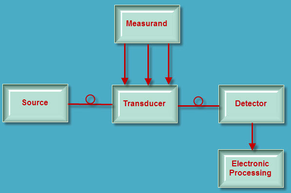
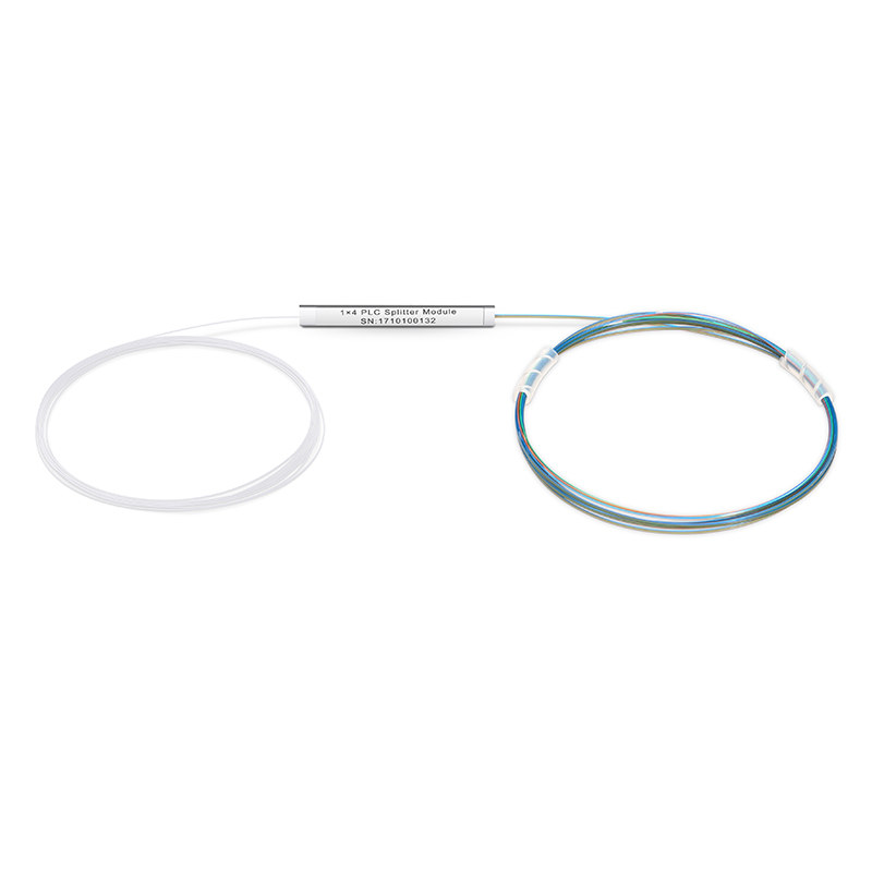
PLC splitter or planar lightwave circuit splitter is a passive component that has the special waveguide made of planar silica, quartz or other materials. It is employed to split a strand of optical signal into two or more strands. PLC splitter also has lots of split ratios, and the most common ones are 1:8, 1:16, 1:32, 1:64, 2:8, 2:16, 2:32 and 2:64. Products usually accord with Telcordia GR-1209-CORE, Telcordia GR-1221-CORE.YD/T1117-2001 standards. There are many types of PLC splitters to meet with different needs in OLT and ONT connection and splitting of optical signals over FTTH passive optical networks.

Importance of PLC Splitter

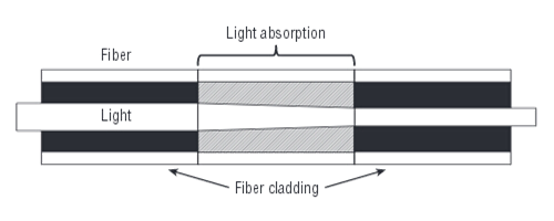
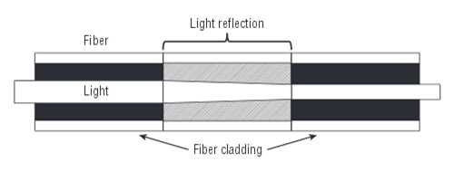
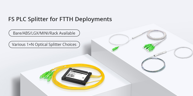
PLC splitter is especially important in FTTH networks, which shares a single PON network with many subscribers. Having no electronics and power in PLC splitter, it is very cost-effective to provide reliable light distribution solutions. Unlike FBT (fused biconical taper) splitter, PLC splitter has a better performance that offers accurate splits with minimal loss in an efficient package. Some typical types are widely used in optical network applications, i.e. bare fiber splitter, blockless splitter, ABS splitter, fan-out splitter, tray type splitter, rack-mount splitter, LGX splitter and mini plug-in type splitter.

Applications of PLC Splitter
 
Bare Fiber PLC Splitter

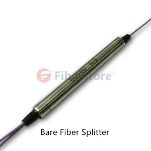
Bare fiber PLC splitter has no connector at the bare fiber ends. It can be spliced with other optical fibers in the pigtail cassette, test instrument and WDM system, which minimizes the space occupation. It is commonly used for FTTH, PON, LAN, CATV, test equipment and other applications.

bare-plc-splitter

Blockless PLC Splitter

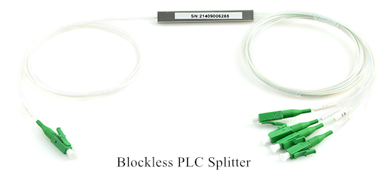
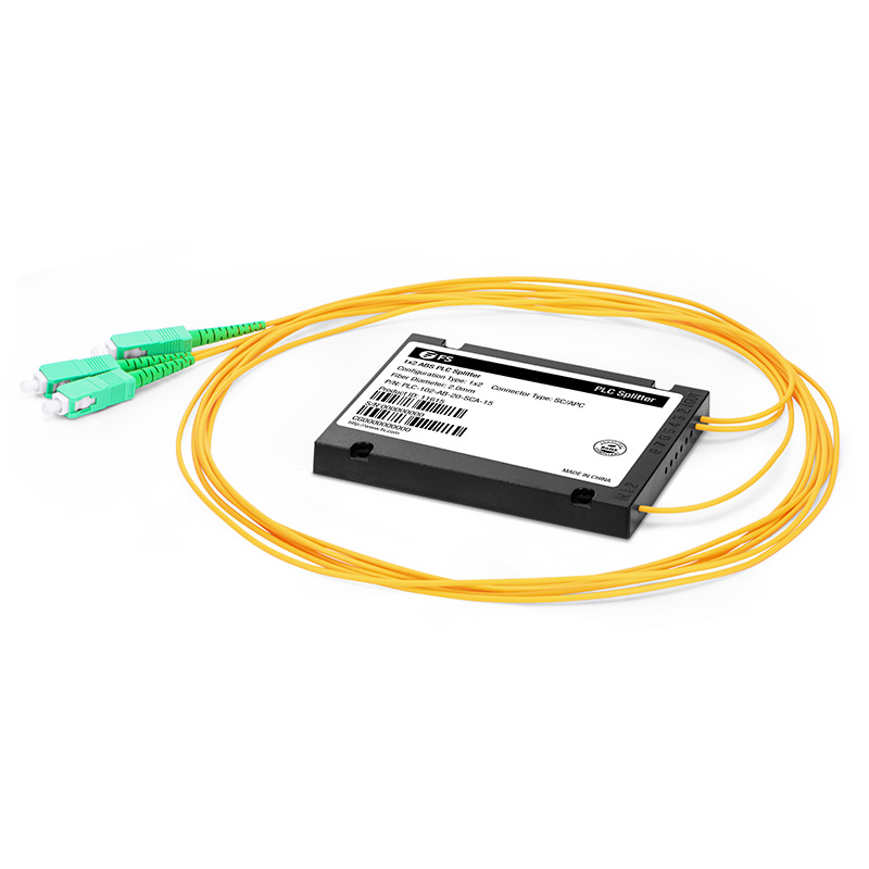
Likewise, blockless PLC splitter has a similar appearance as bare PLC splitter. But it has a more compact stainless tube package which provides stronger fiber protection, and its fiber ends are all terminated with fiber optic connectors. Connectors are commonly available with SC, LC, FC and ST types. Thus, there is no need for fiber splicing during installation. Blockless PLC splitter is mainly used for different connections over distribution boxes or network cabinets.

Blockless-PLC-Splitter

ABS PLC Splitter

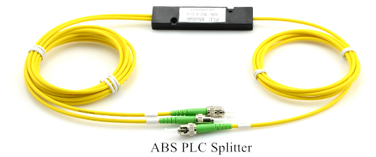
ABS PLC splitter has a plastic ABS box to protect the PLC splitter to adapt to different installation environments and requirements. Common splitter modules are 1×4, 1×8, 1×16, 1×32, 1×64, 2×4, 2×8, 2×16, 2×32. It is widely used with outdoor fiber distribution box for PON, FTTH, FTTX, PON, GOPN networks.

ABS-PLC-Splitter

Fanout PLC Splitter

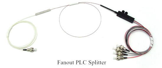
PLC splitter with fan-out is mainly used for 0.9mm optical fiber where the ribbon fiber can convert to 0.9mm optical fiber through fan-out. 1×2, 1×4, 1×8, 1×16, 1×32, 1×64, 2×2, 2×4, 2×8, 2×16, 2×32, 2×64 fanout types are all available with PLC splitters. Fiber adapters can also be used for the input and output ends of this kind of splitters to directly meet the demand on smaller size of splitters.

Fanout-PLC-Splitter

Tray Type PLC Splitter

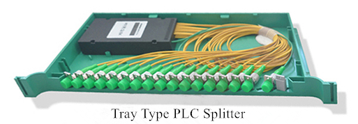
Tray type PLC splitter can be regarded the fiber enclosure which contains PLC fiber splitter inside a enclosure. It is often directly installed in optical fiber distribution box or optical distribution frame. FC, SC, ST & LC connectors are selective for termination. Tray type PLC splitter is an ideal solution for splitting at the places that are near OLT or ONU.

Tray-PLC-Splitter

Rack-mount PLC Splitter

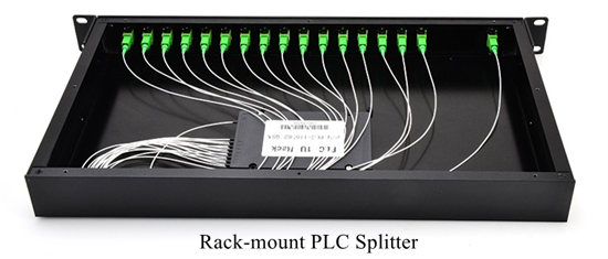
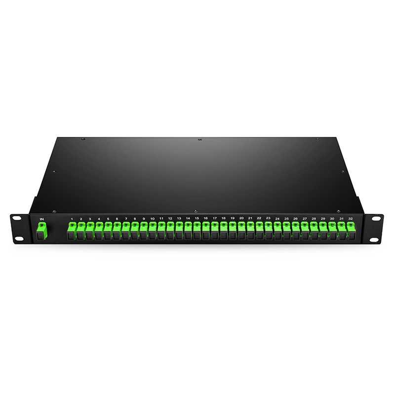
Rack-mount PLC splitter can be used for both indoor and outdoor applications in FTTx projects, CATV or data communication centers. It uses the 19-inch rack unit standard to contain the PLC splitter inside a rack unit.

Rack-mount-PLC-Splitter

LGX PLC Splitter

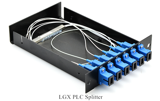
LGX PLC splitter or LGX box PLC splitter has a strong metal box to house the PLC splitters. It can be used alone or be easily installed in standard fiber patch panel or fiber enclosure. The standard LGX metal box housing provides a plug-and-play method for integration in the network, which eliminates any risk during installation. No filed splicing or skilled personnel is required during deployment.

LGX-PLC-Splitter

Mini Plug-in Type PLC Splitter

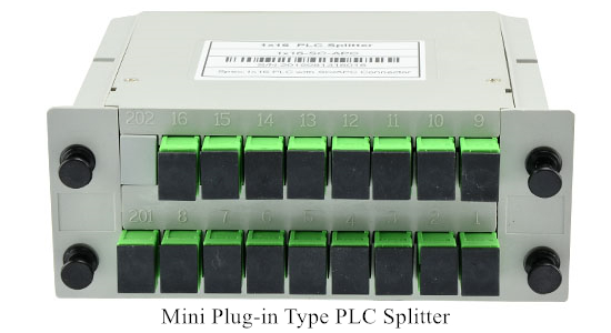
Similar to the LGX PLC splitter, mini plug-in PLC type splitter is its small version with a compact design. It is usually installed in the wall mount FTTH box for fiber optic signal distribution. Using the mini plug-in PLC type splitter saves time and space but still provides reliable protection for the fiber optic splitter.

Mini-Plug-in-Type-PLC-Splitter

Conclusion

These types of PLC splitters are typically installed to serve for PON and FTTH networks. 1xN and 2xN are the common splitter ratios for specific applications. You should choose the most suitable one according to your project. Hope this article provides some help.


Source:

How Many Fiber Optic Splitter Types Are There? – FS Community


Which One Will You Choose for FTTx? PON or AON?

When it comes to FTTx deployment, there are two competing network solutions which are PON (Passive Optical Network) and AON (Active Optical Network). What is the difference between them? And which one will you choose? PON or AON? You may find the answer from the following contents.

PON-AON

PON

A PON consists of an optical line terminator (OLT) located at the Central Office (CO) and a set of associated optical network terminals (ONT) to terminate the fiber–usually located at the customer’s premise. Both devices require power. Instead of using powered electronics in the outside plant, PON uses passive splitters and couplers to divide up the bandwidth among the end users–typically 32 over a maximum distance of 10-20km.

AON

An active optical system uses electrically powered switching equipment to manage signal distribution and direct signals to specific customers. This switch opens and closes in various ways to direct the incoming and outgoing signals to the proper place. Thus, a subscriber can have a dedicated fiber running to his or her house. Active networks can serve a virtually unlimited number of subscribers over an 80km distance.

Advantages and Disadvantages of PON
  • Advantages PON has some distinct advantages. It’s efficient, in that each fiber optic strand can serve up to 32 users. Compared to AON, PON has a lower building cost and lower maintenance costs. Because there are few moving or electrical parts and things don’t easily go wrong in a PON.
  • Disadvantages PON also has some disadvantages. One of the biggest disadvantages is that these splitters have no intelligence, and therefore cannot be managed. Then you can’t check for problems cost-effectively when a service outage occurs. Another major disadvantage is its inflexibility. If one needs to re-design the network or pull a new strand of fiber from the upstream splitter, all downstream customers must come offline for changing the splitter in the network. At last, since PONs are shared networks, every subscriber gets the same bandwidth. So data transmission speed may slow down during peak usage times.
Advantages and Disadvantages of AON
  • Advantages AON offers some advantages, as well. First, its reliance on Ethernet technology makes interoperability among vendors easy. Subscribers can select hardware that delivers an appropriate data transmission rate and scale up as their needs increase without having to restructure the network. Second, it’s about the distance. An active network has the distance limitation of 80 km regardless of the number of subscribers being served. At last, there are some other advantages like high flexibility for deploying different services to residential and business customers, and low subscriber cost.
  • Disadvantages Like PON, AON also has its weaknesses. It needs at least one switch aggregator for every 48 subscribers. Because it requires power, AON inherently is less reliable than PON.

From the above contents, you can find that both technologies have its advantages and disadvantages. In some cases, FTTx systems actually combine elements of both passive and active architectures to form a hybrid system. Thus, to decide which technology to deploy, you should consider your own unique circumstances.

Originally published at www.china-cable-suppliers.com/pon-or-aon-for-fttx.html

Passive Optical Network Technology

The tremendous growth in IP traffic badly influenced the access network capacity. It’s believed that the copper-based access networks can’t provide either the minimum bandwidth or the required transmission distance for delivering services of voice, data, and video programs. Passive optical network (PON) is seemed as a promising and cost-effective way to solve this problem.

What’s PON?

PON is a telecommunication network that uses point-to-multipoint fiber to the end-points in which optical splitters are used to enable a single optical fiber to serve multiple end-points. It does not include any electrically powered switching equipment.

Three Devices in PON

There are three distinct devices in the network (as shown in the following picture): the OLT (optical line terminal), the ONUs (optical network units) or ONTs (optical network terminals) and the splitter. Each one has a necessary function in the passive optical network. PON always works under transmission between the OLT and the different ONT’s through optical splitters, which multiplex or demultiplex signals based on their origin and destination.

PON-devices

  • OLTs are located in provider’s central switching office. This equipment serves as the point of origination for FTTP (Fiber-to-the-Premises) transmissions coming into and out of the national provider’s network. An OLT, is where the PON cards reside.
  • ONU converts optical signals transmitted via fiber to electrical signals. These electrical signals are then sent to individual subscribers. ONUs are commonly used in fiber-to-the-home (FTTH) or fiber-to-the-curb (FTTC) applications. Using different wavelengths for each service makes it possible to transmit high-speed Internet and video services at the same time. Wavelength multiplexing is performed at the central office and a wavelength demultiplexing mechanism is provided at the customer’s house.
  • PON splitter is used to split the fiber optic light into several parts at a certain ratio. For example, a 1X2 50:50 fiber optic splitter will split a fiber optic light beam into two parts, each get 50 percent of the original beam.
Advantages of PON

There are many advantages given by the use of fiber and the passive elements that compose the network. The following will tell about the advantages of PON.

  • High bandwidth The bandwidth allowed by systems based on PON can reach the 10 Gbps rate down to the user. The need to increase the bandwidth and the speed is another justification for the use of PON.
  • Long distance A PON allows for longer distances between central offices and customer premises. While with the Digital Subscriber Line (DSL) the maximum distance between the central office and the customer is only 18000 feet (approximately 5.5 km), a PON local loop can operate at distances of over 20 km.
  • Low cost On one hand, the cost of passive elements is low. On the other hand, the installation of these PON elements is much more economic. And it avoids operation and maintenance costs, such as absence of falls or maintenance of the network feeds.

Of course PON has some disadvantages. Compared with an active optical network, it has less range. That means subscribers must be geographically closer to the central source of the data. PON also make it difficult to isolate a failure when they occur. However, these disadvantages can not avoid choosing PON as the best possible configuration. Because it saves the cost of deploying PON networks regarding other two configurations (point to point and active optical network). And the flexibility of the network allows the usage of a channel by a large number of users.

Article source: http://www.china-cable-suppliers.com/passive-optical-network-technology.html

A Brief Introduction to PON

Optical fiber is reliable and cost-effective, therefore FTTx (fiber to the x) is widely used as a new generation of broadband solutions. How to implement FTTx? PON, passive optical network, is generally considered to be the best approach. The text will provide a basic introduction to PON.

PON Technologies

A passive optical network is a single, shared optical fiber that uses unpowered optical splitters to enable a single optical fiber to serve multiple end-points. PON is a point to multipoint (P2M) network. Each customer is connected into the optical network via a passive optical splitter, therefore, no active electronics in the distribution network and bandwidth is shared from the feeder to the drop. Purely optical passive components in a PON architecture can withstand severe and demanding outside plant environment conditions without the need to consume energy between the central office exchange and the customer premises. The low maintenance requirements of these passive optical components will significantly reduce the cost of upgrades and operating expenditures. The picture below shows a PON architecture.

PON infrastructure

PON Standards

There are three main varieties of PON today: APON/BPON, GPON, EPON.

APON/BPON

ATM (asynchronous transfer mode) passive optical network (APON) was initiated in 1995 by ITU/FSAN and standardized as ITU-T G.983. APON was the first PON based technology developed for FTTH deployment. APON is renamed as broadband passive optical network (BPON). BPON is stable standard that re-uses ATM infrastructure. APON/BPON systems typically have downstream capacity of 155 Mbps or 622 Mbps. Upstream transmission is in the form of cell bursts at 155 Mbps.

GPON

While BPON may still be used in some systems, most current networks use Gigabit passive optical network (GPON) initiated by FSAN in the year 2001 for designing networks over 1Gbps. GPON architecture offers converged data and voice services at up to 2.5 Gbps, and enables transport of multiple services in their native format, specifically TDM and data. GPON uses generic framing procedure (GFP) protocol to provide support for both voice and data oriented services. A big advantage of GPON over other schemes is that interfaces to all the main services are provided and in GFP enabled networks packets belonging to different protocols can be transmitted in their native formats.

EPON

Ethernet passive optical network (EPON) is one of the solutions considered by new IEEE 802.3ah in September 2004, focusing on direct support of Ethernet services. EPON uses CWDM and TDM to provide bi-directional and point-to-point communications over a fiber and maintains frame structure for both upstream and downstream. EPON standards networking community renamed the term ‘last mile’ to ‘first mile’ to symbolize its importance and significance as part of the access network. The system architecture is the same as GPON but data protocols are different.

PON Components

A PON generally consists of an optical line terminal (OLT) at the service provider’s CO (central office), a number of optical network units (ONUs) or optical network terminals (ONTs) near end users, passive optical splitters and transceivers.

OLT
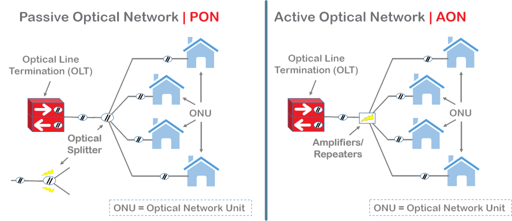
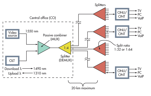
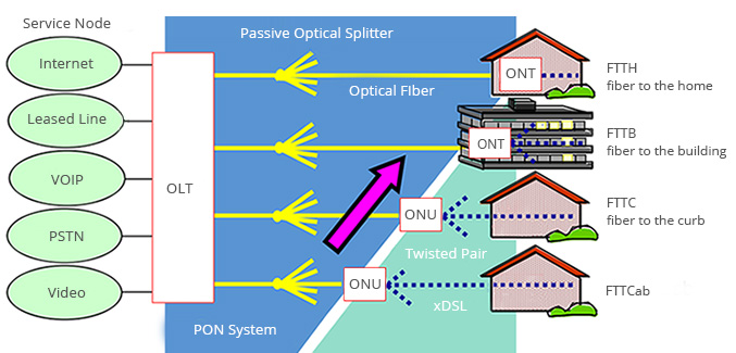
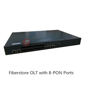
OLT: The optical line terminal is the main element of the network and it is usually placed in the Local Exchange and it’s the engine that drives FTTH system. OLT has two float directions: one is upstream getting distributing different type of data and voice traffic from users, the other is downstream getting data, voice and video traffic from metro network or from a long-haul networkand sending it to all ONT modules on the optical distribution network (ODN). The picture on the left shows an OLT.

ONT
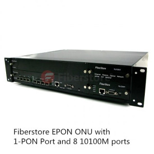
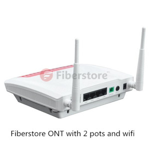
ONU/ONT: Optical network terminals or units are deployed at customer’s premises. ONTs are connected to the OLT by means of optical fiber and no active elements are present in the link. A single ONT can serve as point of access for one or multiple customers and be deployed either at customer’s premises or on the street in a cabinet. The ONU usually communicates with an ONT, which may be a separate box that connects the PON to TV sets, telephones, computers, or a wireless router. The ONU or ONT can be the same device. The picture on the right shows an ONT.

PON Splitter: Passive optical splitters divide a single optical signal into multiple equal but lower-power signals, and distribute the signals to users. The final splitting ratio can be achieved using a single splitter device.

PON Transceiver: PON transceiver is generally a bi-directional device that uses different wavelengths to transmit and receive signals between the OLT at the CO and the ONUs at the end users’ premises over a single fiber. PON transceiver can be divided into OLT transceiver module and ONU transceiver module. OLT transceiver is typically more complex than ONU transceiver.

PON splitter & transceiver

PONs offer low cost connectivity for a large number of users with high security and relatively low management needs. Telecommunications companies use PONs to provide triple-play services including TV, VoIP phone, and Internet service to subscribers. A PON could also serve as a trunk between a larger system, such as a CATV system, and a neighborhood, building, or home Ethernet network on coaxial cable. As PONs grows into millions of homes, it can be seen that a new era of access networks is upon us. Fiberstore offers a series of high reliability and affordable fiber optical access devices for PONs, including OLT, ONU/ONT, PON splitters and transceivers, to meet customers’ fast growing demand of PON deployment.

Introduction of Fiber Optic Sensor

Optical fibers are mainly applied in telecommunications, which has significantly changed this industry. However, there is also a growing application of optical fibers in sensing applications for measurement. Many components associated with optical fibers are developed to sensing applications. One of the most significant components—fiber optic sensor (also known as optical fiber sensor) is now being widely used in sensing applications.

Fiber optic sensors are fiber-based devices to sense some quantities like temperature, pressure, vibrations, displacement, rotations or concentration of chemical species. The basic instrumentation required for sensor are optical source (often a single-frequency fiber laser), sensing element, optical detector and end-prossesing devices (optical-spectrum analyzer, oscilloscope). A block diagram of fiber optic sensor is showed in the following picture.

8-30-2014-10-06-53-AM

Fiber optic sensor offers a wide range of advantages, which makes it being applied in many field successfully. Its advantages are as following.

  • Explosion proof: In fiber optic sensor, the primary signal is an optical. Therefore, there is no risk of spark or fiber.
  • Immunity to electromagnetic interference: Since the fibers are composed of dielectric such as glass. The fiber optic sensor is immune to radio frequency and electromagnetic.
  • Small size, light weight and flexible: This feature extends the applications of fiber optic sensor to many fields, like aircraft.
  • High sensitivity: The optical fiber sensors are highly sensitive and have large bandwidth. When multiplexed into arrays of sensors the large bandwidths of optical fibers themselves offer distinct advantages in their ability to transport the resultant data.
  • Remote sensing: With the availability of low loss optical fibers, the optical signal can be transmitted up to a long distance transmitted up to a long distance (10-1000m). Thus the remote sensing is possible with the optical fiber.
  • Environmental ruggedness and resistant: The optical fiber are manufactured from non-rusting materials such as plastics or glasses, therefore, the fibers have excellent stability when in permanent contact with electrolyte solutions, ionizing radiation etc. Further the fibers can withstand high temperature as high as 350 ca. Special fibers can extend sensor operation beyond 350c to as high as 1200c.
  • Compactness: With the availability of solid-state configurations (small size sources and detectors) it is possible to design a compact optical fiber sensor system.

Based on the sensor location, the fiber optic sensors are generally classified into two types, namely intrinsic and extrinsic fiber optic sensor.

Intrinsic fiber optic sensor can provide distributed sensing over very large distances, which is the most useful feature of it. In intrinsic fiber optic sensor, sensing takes place within the fiber itself. Only a simple source and detector are required. This sensor depends on the properties of the optical fiber itself to convert an environmental action into a modulation of the light beam passing through it. The basic concept of the intrinsic fiber optic sensor is showed in the picture below.

Intrinsic fiber optic sensor

Extrinsic fiber optic sensors use an optical fiber cable, normally a multimode one, to transmit modulated light from either a non-fiber optical sensor, or an electronic sensor connected to an optical transmitter. In this sensor, the fiber may be used as information carriers that show the way to a black box. It generates a light signal depending on the information arrived at the black box. The black box may be made of mirrors, gas or any other mechanisms that generates an optical signal. These sensors are used to measure rotation, vibration velocity, displacement, twisting, torque and acceleration. The major benefit of these sensors is their ability to reach places which are otherwise unreachable. The best example of this sensor is the inside temperature measurement of the aircraft jet engine. The following picture shows the basic concept of the extrinsic fiber optic sensor.

Extrinsic fiber optic sensors

Fiberstore offers fiber optic sensors of high quality. For more information about fiber optic sensor, you can visit its online shop.

Basic of PON

PON, namely, Passive Optical Network, is a telecommunications network that uses ponit-to-multipoint fiber to the premises in which unpowered optical splitters are used to enable a single optical fiber to serve multiple premises. It is an optical-fiber-based network architecture that can provide much higher bandwidth in the access network compared with traditional copper-based networks and is regarded as an ideal solution to last-mile bandwidth bottlenecks. Some of the most primary PON parts and their functions will be introduced in the rest of this article.

Passive optical network

PON consists of an Optical Line Termination (OLT) at the service provider’s Central Office (CO), a number of Optical Network Units (ONUs) and Optical Network Terminals (ONTs) near end users and Optical Distribution Network (ODN) within which optical fibers, fiber optic connectors, passive optical splitters, and auxiliary components collaborate with each other. The above picture shows passive optical network system applied in FTTH/FTTB/FTTC/FTTCab.

OLT is located at the CO. Its main function is to control the information float across the ODN, going both directions. OLT has two float directions: one is upstream getting an distributing different type of data and voice traffic from users, the other is downstream getting data, voice and video traffic from metro network or from a long-haul network and sending it to all ONT modules on the ODN.

Fiberstore EPON ONU with 1-PON Port and 8 10100M ports  Fiberstore OLT with 8-PON Ports

ONT and ONU are basically the same device. ONT is at the customer’s premises to use optical fiber for connecting to the PON on the one side, while interfacing with customers on the other side. ONU receives optical signal and converts it into an electrical signal. However, it is located outside the home, working in different temperature and weather conditions. Thus, ONU should resist water, winds and vandals. There should be an emergency battery backup in ONU in case that the power is off.

ODN containing optical fibers, fiber optic connectors, passive optical splitters, and auxiliary components, is an indispensable path for transmitting PON data and directly affects the performance, reliability, and scalability of a PON system.

Splitter Singlemode Dual Window 250µm Bare Fiber SplitterFiberstore ONT with 2 pots and wifi

The passive optical splitter or PON splitter in ODN is the main part of PON being passive. With a single PON splitter taking one input cable, 32 or 64 subscribers can be served at the same time. In PON the splitters can be arranged in star, ring or tree configurations to increase reliability. There are mainly two kinds of passive optical splitters: one is the traditional fused type splitter as known as FBT coupler or FBT WDM optical splitter, which features competitive price; the other is the PLC splitter based on the PLC (Planar Lightwave Circuit) technology, which has a compact size and suits for density applications.

Fiberstore PON Solution

The mentioned components are the basic parts of PON.  Fiberstore focusing on optical communication for more than 14 years in both technology and manufacturing, can offer perfect PON solution according to customers’ needs. All the mentioned components can be found in the online store of Fiberstore, including but not limited to: OLT, ONT, ONU, splitter, optical fiber and connectors.

Advanced Optical Components – Optical Attenuator

What is Optical Attenuator?

Optical Attenuator (or fiber optic attenuator) is a passive device that is used to reduce the power level of an optical signal. The attenuator circuit allows a known source of power to be reduced by a predetermined factor, which is usually expressed as decibels (dB). Optical attenuators are generally used in single-mode long-haul applications to prevent optical overload at the receiver.

Principles of Optical Attenuators

Optical attenuators use several different principles in order to accomplish the desired power reduction. Attenuators may use the Gap-Loss, Absorptive, or Reflective technique to achieve the desired signal loss. The types of attenuators generally used are fixed, stepwise variable, and continuously variable.

Gap-Loss Principle

The principle of gap-loss is used in optical attenuators to reduce the optical power level by inserting the device in the fiber path using an in-line configuration. Gap-loss attenuators are used to prevent the saturation of the receiver and are placed close to the transmitter. They use a longitudinal gap between two optical fibers so that the optical signal passed from one optical fiber to another is attenuated. This principle allows the light from the transmitting optical fiber to spread out as it leaves the optical fiber. When the light gets to the receiving optical fiber, some of the light will be lost in the cladding because of gap and the spreading that has occurred. The gap-loss principle is shown in the figure below.

Gap-Loss Principle

The gap-loss attenuator will only induce an accurate reduction of power when placed directly after the transmitter. These attenuators are very sensitive to modal distribution ahead of the transmitter, which is another reason for keeping the device close to the transmitter to keep the loss at the desired level. The farther away the gap-loss attenuator is placed from the transmitter, the less effective the attenuator is, and the desired loss will not be obtained. To attenuate a signal farther down the fiber path, an optical attenuator using absorptive or reflective techniques should be used.

Note: The air gap will produce a Fresnel reflection, which could cause a problem for the transmitter.

Absorptive Principle

The absorptive principle, or absorption, accounts for a percentage of power loss in optical fiber. This loss is realized because of imperfections in the optical fiber that absorb optical energy and convert it to heat. This principle can be employed in the design of an optical attenuator to insert a known reduction of power.

The absorptive principle uses the material in the optical path to absorb optical energy. The principle is simple, but can be an effective way to reduce the power being transmitted and/or received. Here is the principle of the absorption of light.

Absorptive Principle

Reflective Principle

The reflective principle, or scattering, accounts for the majority of power loss in optical fiber and again is due to imperfections in the optical fiber, which in this case cause the signal to scatter. The scattered light causes interference in the optical fiber, thereby reducing the amount of transmitted and/or received light. This principle can be employed in the planned attenuation of a signal. The material used in the attenuator is manufactured to reflect a known quantity of the signal, thus allowing only the desired portion of the signal to be propagated. This reflective principle is shown in the figure below.

Reflective Principle

Types of Optical Attenuators

>>According to the principles behind the attenuator theories, there are three types of optical attenuators: Fixed Attenuator, Stepwise Variable Attenuator, and Continuously Variable Attenuator.

Fixed Attenuator

Fixed Attenuators are designed to have an unchanging level of attenuation. They can theoretically be designed to provide any amount of attenuation that is desired. The output signal is attenuated relative to the input signal. Fixed attenuators are typically used for single-mode applications.

Stepwise Variable Attenuator

A stepwise variable attenuator is a device that changes the attenuation of the signal in known steps such as 0.1 dB, 0.5 dB, or 1 dB. These attenuators may be used in applications dealing with multiple optical power sources. For example, if there are three inputs available, there may be a need to attenuate the signal at a different level for each of the inputs. Conversely, they may also be used in situations where the input signal is steady, yet the output requirements change depending on the device that the signal is output to. Note: The stepwise variable attenuators should be used in applications where the inputs, outputs, and operational configurations are known.

Continuously Variable Attenuator

A continuously variable attenuator is an optical attenuator that can be changed on demand. It generally has a device in place that allows the attenuation of the signal to change as required. Continuously variable attenuators are used in uncontrolled environments where the input characteristics and/or output need continually change. This allows the operator to adjust the attenuators to accommodate the changes required quickly and precisely without any interruption to the circuit.

Note: Both the stepwise variable attenuator and continuously variable attenuator are collectively known as Variable Optical Attenuator (VOA). When people talk about the VOA attenuator, it generally means a continuously variable optical attenuator.

>>According to the different connector types, there are several types of optical attenuators: LC attenuator, SC attenuator, ST attenuator, FC attenuator, E2000 attenuator etc., available in UPC/APC polish types.

Packaging of Optical Attenuators

Optical attenuators typically come in two forms of packaging: bulkhead attenuator and in-line attenuator. The bulkhead optical attenuators can be plugged into the receiver receptacle. The in-line optical attenuators resemble a fiber patch cord and is typically used between the patch panel and the receiver. Here are a 10 dB Fixed LC/UPC Bulkhead Optical Attenuator and a 0~60 dB LC/UPC to LC/UPC In-Line Variable Optical Attenuator from Fiberstore.

10 dB Fixed LC/UPC Bulkhead Optical Attenuator 0~60 dB LC/UPC to LC/UPC In-Line Variable Optical Attenuator