
Mode conditioning patch cord (MCP) was developed as a solution for network applications where Gigabit Ethernet hubs with laser based transmitters are deployed. It is a special fiber optic patch cord and allows customer upgrading their hardware technology without the cost of upgrading fiber plant. In addition, MCP significantly improves data signal quality while increasing the transmission distance. The text will give some detailed information about mode conditioning patch cable.
A mode conditioning patch cord is a duplex multi-mode patch cord that has a small length of single mode fiber at the start of the transmission leg, and also a single mode to multi-mode offset fiber connection part in this leg. There are two multi-mode fibers on one end and one multi-mode and one single mode fiber on the other end. It is fully compliant with IEEE 802.3z application standards. Mode conditioning patch cord causes the single mode transceiver to create a launch similar to a typical multi-mode launch. It is designed for long wavelength Gigabit Ethernet applications. The following picture shows the construction of a mode conditioning patch cable.
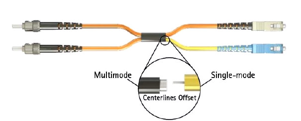
The basic principle behind the cord is that you launch your laser into the small section of single mode fiber. The launch of the light coming out of the equipment begins on a single mode fiber. The other end of the single mode fiber is coupled to multi-mode section of the cable with the core offset from the center of the multi-mode fiber. The light is launched on to the multi-mode fiber at a precise angle, giving the cable its mode conditioning properties. When we use such mode conditioning fiber optic patch cords, we need to connect the yellow leg which is the color of single mode to connect the transmit side of the equipment (single mode Gigabit transceiver) while we connect the orange leg which is the color of multi-mode to the receive side. The picture below shows how the single mode fiber is coupled to multi-mode section of the cable.

To install a mode conditioning patch cable, you need to follow these steps:
- Step1: Connect the yellow leg (single mode connector) of the MCP cable into the transmit bore of the transceiver.
- Step2: Connect the rest orange legs (multi-mode connectors) of the MCP cable into the receive bore of the transceiver.
- Step3: At the other end of the patch cord, put all the orange legs (multi-mode connectors) into the patch panel.
- Step4: Repeat the above three steps for the second transceiver located at the other end of the network link.
After you have finished all the connection steps above, all the swap of transmit and receiver can only be done at the cable plant side.
Transceiver modules used in Gigabit Ethernet (1000 Base-LX) launch only single mode (1300nm) long wave signals, which poses a problem if an existing fiber network utilizes multi-mode cable. When a single mode signal is launched into a multi-mode fiber a phenomenon known as differential mode delay (DMD) can create multiple signals within the multi-mode fiber. This effect can confuse the receiver and produce errors. By allowing the single mode laser launch to be offset away from the center of the multi-mode fiber, mode conditioning patch cord reduces the effect of such differential mode delay and provides a much higher operational bandwidth by precisely aligning a single mode termination at the laser transmitter. This is essential for networks using 62.5/125 and 50/125 multi-mode optical fiber and may be specified for current multi-mode networks depending upon the system requirements.
Mode conditioning patch cables are with various options, from all types of connectors to different jackets and different lengths. A variety of fiber optic connectors are available for your convenience, including: LC/UPC, SC/UPC, FC/UPC, ST/UPC, LC/APC, SC/APC, FC/APC, and MTRJ. Mode conditioning patch cables are built in the form of a simple duplex patch cable, so they can easily be installed in a system without the need for additional components or hardware. Their length can range from one meter and up to support virtually any network topography.