Visual Fault Locator Overview

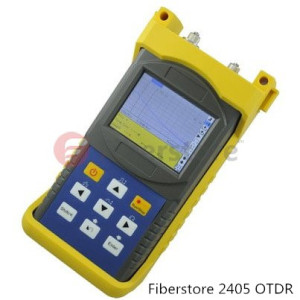
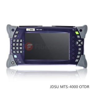
Whether install new fiber links or troubleshooting an existing network, the faster you can locate a problem, the faster you can fix it. To locate the faults in fiber optic cables in a short time, various fiber optic testers are being invited to locate the faults of the fiber optic cable, like OTDR (optical time-domain reflectometer). However, OTDR has dead zone during the testing. Another simple and useful tester which can work in an OTDR dead zone is usually being used to work as an accessory of OTDR. It is known as VFL (visual fault locator) which can also work alone to locate the faults in fiber optic cable in a time saving manner in some situations.

What Is VFL?

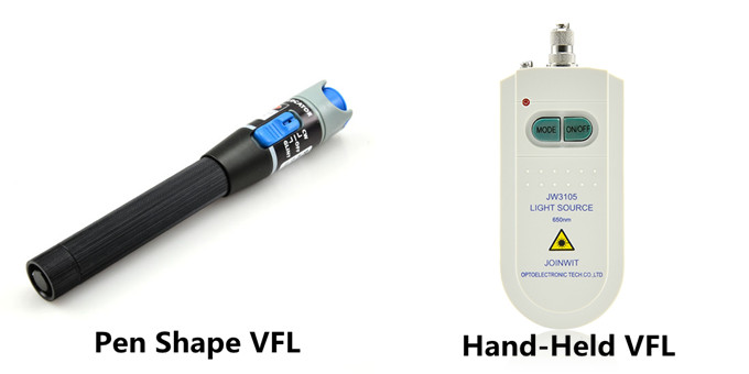
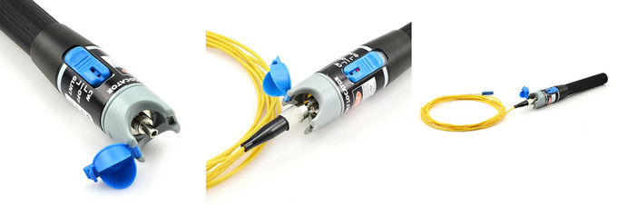
Visual fault locator is now one of the most commonly used fiber optic testing devices to trace optical fibers, check fiber continuity and find faults such as breaks, bad splices and tight, sharp bends in fiber optic cable. The most popular visual fault locators are pen shape VFL and hand-held VFL, which are showed in the following picture respectively.

pen shape VFL and hand-held VFL

How VFL Works

The light used for transmit signals over fiber optic is usually at 1300 to 1650nm wavelength which is invisible to naked eyes. Unlike OTDR which measures the time of the incidence and the amplitude of the reflected pulses sent to the fiber optic cable to locate the faults, VFL uses powerful visible light at the 360 to 670nm wavelength injecting to a fiber to visually and directly locate the faults in fiber optic cable. The visible light travels along the core until it reaches a fault, where it leaks out. Light leaking through the fault can be seen through plastic coating and jackets under suitable illumination. This is how VFL locates the faults in fiber optic cable.

Visual fault locators radiate in continuous wave (CW) or pulse modes. The glint of the light source in VFL is usually at 1 or 2 Hz, kHz range is also being provided in today’s market. The output power is generally at 1 mW or less. The working distance of a VFL is usually in the range of 2 to 5 km.

How to Use VFL

VFL is very easy to use. The steps to use a VFL are provided as following:

  • Step One: remove the plastic connector covers from both ends of the test fiber cable.
  • Step Two: connect the fiber optic visual fault locator one end of the fiber. Press the tester button and observe that light emanates from the other end of the fiber. This gives a simple indication of the continuity of the fiber link.
  • Step Three: repeat with several other fibers. Check for light that can be seen leaking from a faulty splice. This may illustrate an easy way of carrying out visual fault finding on bad splices or joints.
  • Step Four: disconnect all equipment, put the plastic covers back on the connector ends and return everything to the state it was in before you started the practical so that the next group can carry out the practical in full.

VFL

Notes during the using of a VFL:

  • 1.Never look directly into the VFL’s output.
  • 2.Cover the VFL’s output with the dust cap when the VFL is not in use.
  • 3.Not recommended for use on dark colored or armored cables.

Using simple but useful technical principle, visual fault locator individually can provide an economic and time saving solution to locator faults in fiber optic cables in some cases. While working as an accessory of OTDR, VFL, together with OTDR, can provide the fiber technician the best solution to locate fiber faults.

7 Factors to Consider before Selecting An OTDR

An OTDR (Optical Time Domain Reflectometer) is a fiber optic tester for the characterization of optical networks that support telecommunications. The purpose of an OTDR is to detect, locate, and measure elements at any location on a fiber optic link. An OTDR needs access to only one end of the link and acts like a one -dimensional radar system. By providing pictorial trace signature of the fibers under test, it’s possible to get a graphical representation of the entire fiber optic link.

Fiberstore2405 OTDR

An OTDR can be used to measure optical distance including locations of the elements like splices, connectors, splitters, multiplexers and faults, as well as end of fiber. Loss and Optical Return Loss (ORL)/Reflectance, such as loss of splices and connectors, ORL of link or section, reflectance of connectors and total fiber attenuation can also be tested by OTDRs.

Not all OTDR are made the same. There are various kinds of OTDR models available, addressing different test and measurement needs. The choosing of an OTDR is based on applications. By thinking of the following questions, you can roughly know what kind of OTDR you need.

  • What kind of networks will you be testing? LAN, metro, long haul?
  • What fiber type will you be testing? Multimode or single-mode?
  • What is the maximum distance you might have to test? 700 m, 25 km, 150 km?
  • What kind of measurements will you perform? Construction(acceptance testing), troubleshooting, in-service?

JDSU MTS-4000 OTDR

Fiberstore offers you 7 factors to help you figure out which OTDR best fits your applications.

  • Size and Weight: important if you have to climb up a cell tower or work inside a building.
  • Display Size: 5″ should be the minimum requirement for a display size; OTDRs with smaller displays cost less but make OTDR trace analysis more difficult.
  • Battery Life: an OTDR should be usable for a day in the field; 8 hours should be the minimum.
  • Trace or Results Storage: 128 MB should be the minimum internal memory with options for external storage such as external USB memory sticks.
  • Bluetooth and/or WiFi Wireless Technology: wireless connectivity enables easily exporting test results to PCs/laptops/tablets.
  • Modularity/Upgradability: a modular/upgradable platform will more easily match the evolution of your test needs; this may be more costly at the time of purchase but is less expensive in the long term.
  • Post-Processing Software Availability: although it is possible to edit and document your fibers from the test instrument, it is much easier and more convenient to analyze and document test results using post-processing software.

Before selecting an OTDR, consider the applications that the instrument will be used for and check the OTDR’s specifications to ensure that they are suited to your applications.

Fiberstore OTDR Solution

Fiberstore OTDRs are available with a variety of fiber types and wavelengths, including single mode fiber, multimode fiber, 1310nm, 1550 nm, 1625 nm, etc. It also supplies OTDRs of famous brands, such as JDSU MTS series, EXFO, YOKOGAWA AQ series and so on. You can find the OTDR best fit your applications in Fiberstore.