Fiber Splice Tray & Wall Mount Network Cabinet–For Better Cabling

Cabling is not some easy thing. Many problems might come out while cabling. Sometimes the fiber optic cable is not long enough. Sometimes there are too many fiber optic cables that need great efforts to ensure the management of them. The protection and maintenance of the fiber optic cable are also essential. These are just some of the most common problems that people meet during cabling. In this article, two common and useful products will be introduced to help you solve the most common problems while cabling. They are fiber splice tray and wall mount network cabinet.

Fiber Splice Tray
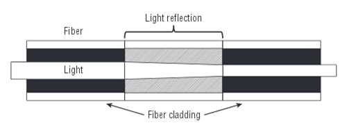
Fiber splice tray is a kind of optical distribution frame. Generally, fiber splice tray is a container used to organize and protect fibers and spliced fibers. It is designed to provide space for the connection of fibers and spliced fibers.
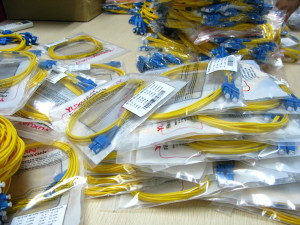
Different fiber optic cables can be melted connected directly via the fiber splice tray. In addition, fiber optic cable can be connected with pigtail via the tray, and via the pigtail it can connect out to their fiber optic equipment. With the help of fiber splice trays, the problem that the fiber optic cable is not long enough can be solved. Fiber splice tray is made of engineering plastics and it features as flame retardant, high strength and aging resistance. Thus it can protect the fiber and spliced fibers very well. In addition, as the fiber splice tray provides space to hold the melted connected fibers and spliced fibers, it can help to manage the fiber optic cables to some degree. This function can be seen from the picture of a splice tray below:
OLYMPUS DIGITAL CAMERA
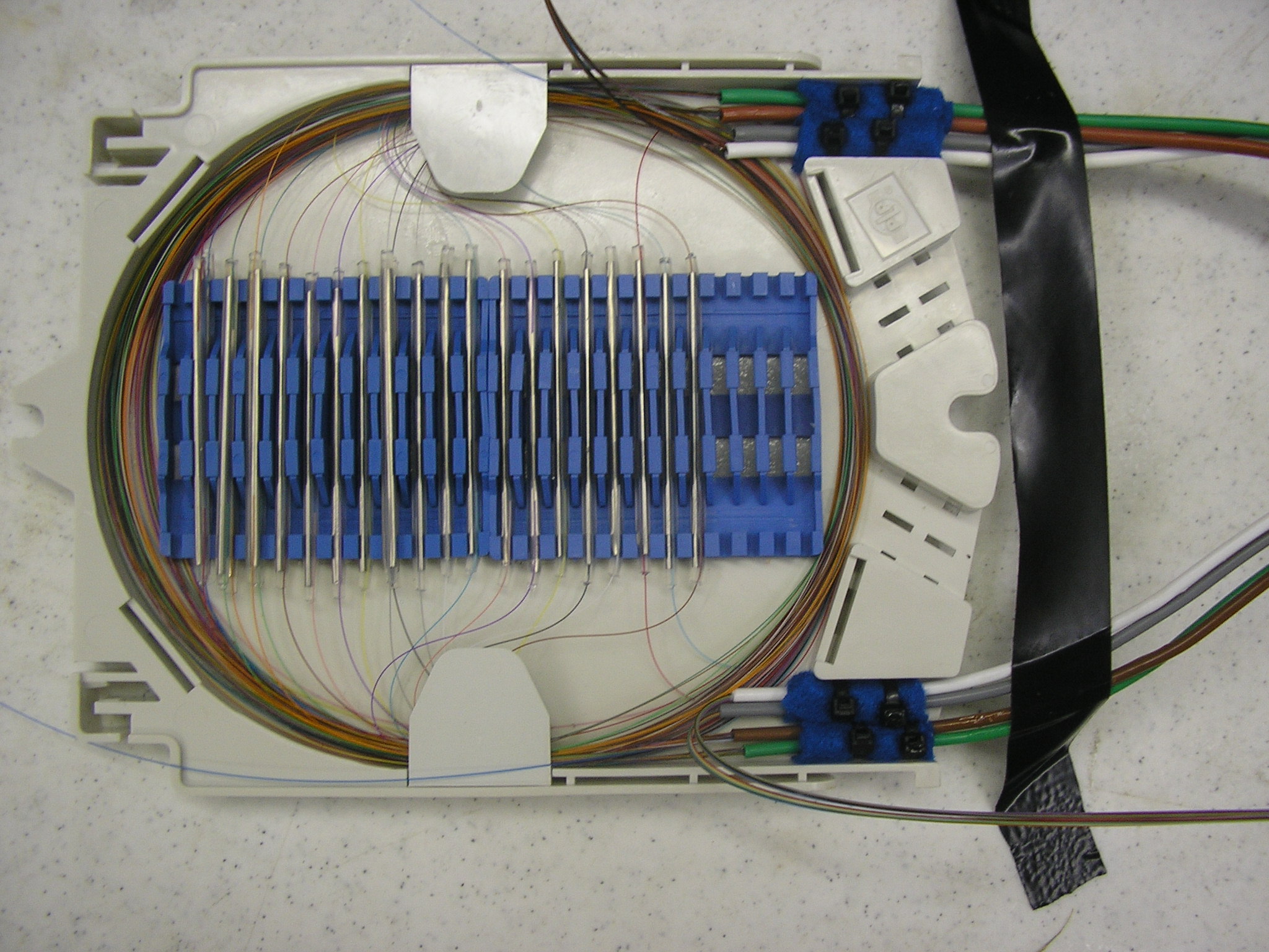
Fiber splice tray is one of the most common components being used during cabling. It can offer various of unique and flexible splice and storage possibilities.

Wall Mount Network Cabinet
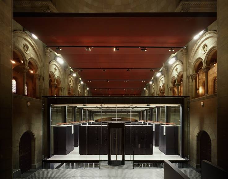
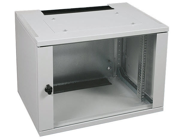
Wall mount network cabinet is one of the most commonly used distribution cabinets. It provides a flexible fiber management system for transitioning outside plant cable to inside cable and connector assemblies and can be installed on the wall.
Wall mount network cabinet has great advantages in fiber optic cable management and protection. The wall mount network cabinet is usually layered structure, which helps a lot while organizing equipment and cabling in limited space. Moreover, the maintenance of fiber optic cables connected with wall mount network cabinet is very convenient and efficient. The cabinet generally contains power supply and fan, which can help the fiber optic cables work well and work longer. Various sizes and types of wall mount network cabinets are provided. Factories install different adapters in the cabinet to satisfy the needs of the markets. Costum-made cabinet is also very popular.

wall mount cabinet 2 wall mount cabinet
With the help of wall mount network cabinets, cabling work will be much more easier and systematic. The cabinet provides a safe place for the fiber optic cables connection in limited space. It is now widely used in the cabling of various areas.

The choice of appropriate components during cabling does not only simplify the work, but also helps a lot in cost saving, space savings, products operation and maintenance. Fiberstore Inc. designs, manufactures and sells a comprehensive line of high performance, highly reliable fiber optic communication systems and modules for metropolitan area, local area and storage area networks. Fiberstore can provide different sizes of wall mount network cabinets and various types of fiber splice trays which can contain 4 fibers, 6 fibers, 12 fibers, 16 fibers, 24 fibers, 32 fibers and so on.

LSZH Fiber Optic Cable

When choosing the fiber optic cable for any application, we need to consider the environment where the fiber optic cable will be used. Will the fiber optic cables work well and safely in the environment? What might happen if the cables meet some extreme situations? We must take human safety and environmental protection into consideration when selecting the appropriate cabling solution. Then you can concern the LSZH fiber optic cable in a lot of situations.

LSZH-Distribution-Cable

What is LSZH Fiber Optic Cable?
LSZH fiber optic cable has no difference from other fiber optic cables, but it has a special cable jacket which is made of LSZH materials. LSZH stands for Low Smoke, Zero Halogen. This type of cable jacket has excellent fiber safety characteristics of low smoke, low toxicity and low corrosion. This is because LSZH materials are free of halogenated materials like Fluorine (F), Chlorine (Cl), Bromine (Br), Iodine (I) and Astatine (At), which are reported to be capable of being transformed into toxic and corrosive matter during combustion and decomposition. LSZH fiber optic cable is now being widely used in many places.

Characteristics of LSZH Fiber Optic Cable
The main characteristics of LSZH fiber optic cables are as following:

  • Release no dangerous smoke and gas during confusion
  • Low emission of toxic gases and halogens during decomposition
  • Low corrosion
  • High flame retardant

The Types of LSZH Fiber Optic Cable
Currently, there are hundreds of different kinds of LSZH fiber optic cables provided for many different uses. The major types of LSZH fiber optic cables now being provided are as following:

  • Single-mode LSZH fiber optic cables
  • Multi-mode LSZH fiber optic cables
  • Double jacket LSZH fiber optic cables
  • Single jacket LSZH fiber optic cables
  • Gel-filled LSZH fiber optic cables
  • Strength membered LSZH fiber optic cables
  • FTTH LSZH fiber optic cables
  • Indoor LSZH fiber optic cables
  • Outdoor LSZH fiber optic cables

Why do We Choose LSZH Fiber Optic Cable?
For the Safety
According to researches, most fire-related deaths are not actually caused by the fire, but by inhalation of large quantities of smoke and toxic gas. Wires and cables might be damaged and burned by the fire and short circuit. Some cables like PVC will release a lot of toxic gas and corrosive matter during the fire. As LSZH material has the characteristics of low smoke, low toxicity, low corrosion and high flame retardant, the choosing of LSZH fiber optic cable in some public space like train, hospital, subway and school is really necessary.
Go for Green
The LSZH fiber optic cable has an environment friendly cable jacket, which satisfies the global need of environment protection. It releases low smoke and low toxic matter during the confusion and decomposition. There is no reason not to use LSZH fiber optic cable when it is appropriate, because the environmental protection is now a pressing problem all over the world.
LSZH fiber optic cable with a good performance in the environmental protection and safety, can be a good choice of many cable installations.

Applications of LSZH Fiber Optic Cable
LSZH fiber optic cable now can be found in many places, especially some public places. Now some places have been asked to use LSZH fiber optic cable in the cabling solution because of its performance. The major uses of LSZH fiber optic cable can be found in the following areas.

  • Hospitals
  • Schools
  • High buildings
  • Airports
  • Libraries
  • Commercial centers
  • Sports centers
  • Mass transit rail systems
  • Nuclear plants
  • Oil refineries and any other applications where the protection of people and equipment from toxic matter and gases is critical.

Now with the development of cables, many areas are using LSZH fiber optic cables. However, the application of LSZH fiber optic cables can still be found in many other areas in the future. It is a kind of fiber optic cable with great prospect.

How to Prevent the Damage caused by Lightning in Fiber Cabling

With the development of the network communications, the optical fiber as a medium used in the integrated cabling systems to transmit data is used by more and more people, because of its advantages such as large transmission rate and distance. It is well known that optical fiber has no electrical conductivity and can prevent from impact current. Fiber optic cables have good protection performance, and the metal components of cable’s insulation value is so high that lightning current can not enter the cable easily. However, because fiber optic cable has strengthened core, especially the direct-buried fiber optic cable has armoring layer, thus when the optical fiber cable line experience lightning, the cables might be destroyed or damaged. And this blog talks about the main measures of lightning protection in fiber cabling.

Lightning Protection for Direct-Buried Fiber Optic Cables

  • Station Grounding Method: the metal part of the cables in the joints should be all connected to make sure the strengthened cores, moistureproof layers, and armoured layers are in connected state in the relay cable lines.
  • Electrical Disconnect Treatment should be done in the cable tapping of moistureproof layers, armoured layers and strengthened cores, and do not connect the ground for the insulation status. This method can avoid the accumulation of induced lightning current in the cables. Also, it can avoid lightning current enetr in the cables by grounding devices, which is caused by the difference of loop impedance to ground between the lightning discharge flow and the cables’ metal components.

Lightning Protection for Aerial Fiber Optic Cables

Aerial fiber optic cables should be electrical connected and connected to the ground every 2 km. The grounding can be directly done or or by suitable surge protection devices.

Typical Lightning Protection for Fiber Optic Cables

After fiber optic cables enter the fiber optic terminal boxes, the boxes should be connect to the ground so they can rapidly release the lightning current to realize the protection when the lightning current enter the fiber optic cables’ metal layers. When using direct-buried fiber optic cables with armoured layers and strengthened cores, the polyethylene outer sheath can be effectively anticorrosive and prevent from rat bites as well as the lightning stroke.

Article Source: http://www.fiberopticshare.com/how-to-prevent-the-damage-caused-by-lightning-in-fiber-cabling.html

Fiber Optic Connector: An Important Part of Fiber Optic Termination

Fiber optics are used for a variety of applications in the photonics industry. Fiber optics are typically connectorized for convenience of mating and coupling. These connectors come in many configurations and styles. A fiber optic connector that was lower loss, lower cost, easier to terminate or solved some other perceived problem is urgently needed to the industry. As a result, about 100 fiber optic connectors have been introduced to the marketplace, but only a few represent the majority of the market. Today, Fiberstore’s Blog are going to show you these commonly used fiber optic connectors.

fiber optic connector

Fiber Optic Connector Types
Commonly used fiber optic connector types include SC, FC, LC, ST, MU, E2000, MTRJ, SMA , DIN as well as MTP & MPO etc. They are widely used in the termination of fiber optic cables, such as fiber optic pigtail, fiber optic patch cables and so on.

LC connector LC Connector (Lucent Connector) — Ferrule diameter = 1.25mm. LC connectors are licensed by Lucent and incorporate a push-and-latch design providing pull-proof stability in system rack mounts. LC connectors are available in single mode and multimode. Externally LC connectors resemble a standard RJ45 telephone jack. Internally they resemble a miniature version of the SC connector. This type of connectors are commonly used in connecting SFP Transceiver Module in Router/Switch. For example, the optic interfaces of Cisco’s SFP transceivers are all LC connectors.
SC connector SC Connector (Subscriber Connector) — Ferrule diameter = 2.5mm. The SC connector is becoming increasingly popular in single-mode fiber optic telecom and analog CATV, field deployed links. But the most commonly used field is to connect GBIC (100Base-FX) in router/switch. The high-precision, ceramic ferrule construction is optimal for aligning single-mode optical fibers. The connectors’ outer square profile combined with its push-pull coupling mechanism, allow for greater connector packaging density in instruments and patch panels. The keyed outer body prevents rotational sensitivity and fiber endface damage. Multimode versions of this connector are also available. The typical insertion loss of the SC connector is around 0.3 dB.
ST connector ST Connector (Straight Tip) — Ferrule diameter = 2.5mm. ST connector’s high-precision, ceramic ferrule allows its use with both multimode and single-mode fibers. The bayonet style, keyed coupling mechanism featuring push and turn locking of the connector, prevents over tightening and damaging of the fiber end. The insertion loss of the ST connector is less than 0.5 dB, with typical values of 0.3 dB being routinely achieved. ST connector is used extensively both in the field and in indoor fiber optic LAN applications, eg. ODF (optical distribution frame). In addition, ST connector is also used to connect GBIC transceiver, usually for 100Base-F.
FC connector FC Connector (Ferrule Connector) — Ferrule diameter = 2.5mm. The FC has become the connector of choice for single-mode fibers and is mainly used in fiber-optic instruments, SM fiber optic components, and in highspeed fiber optic communication links. This high-precision, ceramic ferrule connector is equipped with an anti-rotation key, reducing fiber endface damage and rotational alignment sensitivity of the fiber. The key is also used for repeatable alignment of fibers in the optimal, minimal-loss position. Multimode versions of this connector are also available. The typical insertion loss of the FC connector is around 0.3 dB.
MU connector MU Connector (Miniature Unit) — Ferrule diameter = 1.25mm. MU is a small form factor SC. It has the same push/pull style, but can fit 2 channels in the same Footprint of a single SC. MU was developed by NTT. It is a popular connector type in Japan. Applications include high-speed data communications, voice networks, telecommunications, and dense wavelength division multiplexing (DWDM). MU connectors are also used in multiple optical connections and as a self-retentive mechanism in backplane applications.
MTRJ connector MTRJ Connector (Mechanical Transfer Registered Jack) — Ferrule diameter = 2.45×4.4 mm. MT-RJ is a duplex connector with both fibers in a single polymer ferrule. It uses pins for alignment and has male and female versions. Multimode only, field terminated only by prepolished/splice method.
E2000 connector E2000 Connector — Ferrule diameter = 2.5mm. E2000 connector is a plastic push-pull connector developed by Diamond. The E2000 was developed as an improvement on the SC connector design by having: a latch that retains the connector, a dust cap always in place, and a smaller size. The built in dust cap always stays on the connector protecting the ferrule and blocking harmful laser light when the connector is disconnected. E2000 is available for Singlemode and Multimode applications.
sma SMA Connector (Sub Miniature A) — Ferrule diameter = 3.14mm. Due to its stainless steel structure and lowprecision threaded fiber locking mechanism, this connector is used mainly in applications requiring the coupling of high-power laser beams into large-core multimode fibers. Typical applications include laser beam delivery systems in medical, bio-medical, and industrial applications. The typical insertion loss of an SMA connector is greater than 1 dB.
DIN connector DIN Connector — Ferrule diameter = 2.5mm. DIN connector is a metal screw on connector which is developed by Siemens. Deutsch Telecom mainly uses it. This is a good connector to use where the ruggedness of a metal screw on connector is required but
where there is not enough space for a FC Connector.
mtp&mpo connector MTP and MPO Connector — MTP and MPO are compatible ribbon fiber connectors based on MT ferrule which allow quick and reliable connections for up to 12 fibers. They are intended for installations that require many fiber connections. Up to 12 fibers in a ribbon are stripped to 125um cladding and inserted into 250um spaced parallel grooves. The ferrule also includes two 0.7mm diameter holes, running parallel to the fibers on the outer side of the ferrule. These two holes hold precision metal guide pins which align the fibers with tight tolerances. MTP and MPO connectors feature male and female connector design. Male connectors have two guide pins and female connectors do not. Both connector types need an adapter to mate a pair of male and female connectors. Because MTP and MPO connectors are trying to align so many fibers at once, their coupling loss are typically bigger than single fiber connectors.


History of Different Connector Types
The ST connector is the oldest design of the connectors still in common use. It was the first connector to use a 2.5mm ferrule. The FC and DIN connectors improved on the ST connector by: isolating cable tension from the ferrule, keying the location of the ferrule for angle polishing, and threading onto the adapter for a more positive connection. The SC connector was then developed to eliminate having to screw and unscrew the connector every time and to reduce the cost by molding instead of machining the connector. A big advantage of this push/pull connector over a FC connector is that less room is required between connectors on patch panels. The E-2000 was developed as an improvement on the SC connector design by having: a latch that retains the connector, a dust cap always in place, and a smaller size. As patch panel densities increased the LC and MU connectors were developed to reduce the space required for connectors on patch panels. Both of these connectors use a 1.25mm ferrule. The MT-RJ connector was then developed to put transmit and receive fibers into one connector. This was the first connector to use the MT ferrule design as opposed to a 2.5mm or 1.25mm diameter ferrule. The MTP connector was then developed to increase fiber density even more. The MTP currently has 12 fibers in its MT ferrule however a 24-fiber version is under development.

There are many more influences that lead to the development of these different commonly used connector types. This is why all of the different connector types exist. In fact, there are not only these connector types. A multitude of specialty connectors are launched to the market for different application.

Connector Endface Preparation
Once the optical fiber is terminated with a particular connector, the connector endface preparation will determine what the connector return loss, also known as back reflection, will be. The back reflection is the ratio between the light propagating through the connector in the forward direction and the light reflected back into the light source by the connector surface. Minimizing back reflection is of great importance in high-speed and analog fiber optic links, utilizing narrow line width sources such as DFB lasers, which are prone to mode hopping and fluctuations in their output.

polishing type

Flat Polish — a flat polish of the connector surface will result in a back reflection of about -16 dB (4%).
PC Polish — the Physical Contact (PC) polish results in a slightly curved connector surface, forcing the fiber ends of mating connector pairs into physical contact with each other. This eliminates the fiber-to-air interface, there by resulting in back reflections of -30 to -40 dB. The PC polish is the most popular connector endface preparation, used in most applications.
UPC/SPC Polish — in the Super PC (SPC) and Ultra PC (UPC) polish, an extended polishing cycle enhances the surface quality of the connector, resulting in back reflections of -40 to -55 dB and < -55dB, respectively. These polish types are used in high-speed, digital fiber optic transmission systems.
APC Polish — the Angled PC (APC) polish, adds an 8 degree angle to the connector endface. Back reflections of <-60 dB can routinely be accomplished with this polish.

Article Source: http://www.fs.com/blog/fiber-optic-connector-an-important-part-of-fiber-optic-termination.html

Cost-effective Capacity Growth and Investment Protection — Hybrid DWDM/CWDM

Introduction of Hybrid DWDM-CWDM

CWDM is an excellent, cost-effective, first step solution for scaling metro networks. Low cost hybrid DWDM-CWDM modules can support up to 8 channels at 2.5 Gbps. This is sufficient for many networks in the metro space. If capacity needs grow beyond 8 channels, these modules can be used to merge DWDM and CWDM traffic seamlessly at the optical layer. This allows carriers to add many channels to networks originally designed for the more limited CWDM capacity and reach.

Hybrid DWDM-CWDM technology delivers true pay-as- you-grow capacity growth and investment protection. It offers a simple, plug-and-play option for creating hybrid systems of DWDM channels interleaved with existing CWDM channel plans.


Advantages of Hybrid DWDM-CWDM

The major advantages of hybrid DWDM-CWDM for carriers are as following:

  • Reduced Cost: CWDM has a significant cost advantage over DWDM due to the lower cost of lasers and the filters used in CWDM modules (CWDM MUX, CWDM OADM etc.). Coarse channel spacing allows more tolerance for channel deviations or wavelength deviations. Therefore, CWDM filters and transmitters are easier, and cheaper, to manufacture. This cost saving becomes quite significant for large deployments.
  • Pay-As-You-Grow: Adding new channels one at a time allows for on-demand service introduction with minimal initial investment, a critical feature in times of reduced OPEX and CAPEX spending.
  • Investment Protection: Although 8 channels may be enough in an initial deployment, it’s important to have an upgrade path to avoid a forklift upgrade to DWDM when growth in demand finally requires significant new capacity. Given the DWDM over CWDM upgrade capability, carriers no longer have to choose between CWDM and DWDM—both options can be deployed simultaneously or as part of a planned future, or incremental, upgrade. Hybrid DWDM-CWDM modules can be used in either the DWDM systems or in the CWDM systems. Current capital investment can always be used in the upgraded network.

Theory of DWDM/CWDM Hybridization

The CWDM frequency grid consists of 16 channels spaced at 20 nm intervals. The eight most commonly used channels are: 1470 nm, 1490 nm, 1510 nm, 1530 nm, 1550 nm 1570 nm, 1590 nm and 1610 nm. Within the pass band of these channels there exists the capacity to add twenty-five 100 GHz spaced DWDM channels under the 1530 nm envelope and twenty-five more under the 1550 nm envelope if the filter is properly designed. The theoretical availability of DWDM channels in the 1530 nm and 1550 nm pass-band is shown in the table below.

Theoretical DWDM Channels in the 1530 and 1550 nm CWDM Pass-Band


Practical Application of DWDM/CWDM Hybridization

In practice, adding another 25 DWDM channels in the pass-band of both the 1530 nm and 1550 nm CWDM channels is not achievable because the optical filters are not perfect square functions. The actual filter profile affects the number of channels which can be accommodated. However, actual DWDM filter technology does allow 38 additional channels to clear the CWDM archway as shown in the table below.

Actual DWDM Channels in the 1530 and 1550 nm CWDM Pass-Band

The system impact to adding these channels is equivalent to adding the component in line with existing CWDM equipment. The insertion losses add linearly. Here is a figure that shows the infrastructure in a fully populated CWDM system.

Infrastructure of Hybrid DWDM CWDM System

To add more channels to MUX side of this network, one would plug in a DWDM MUX with the appropriate channels to fall under the pass-band of the existing CWDM filters. The figure below shows the infrastructure of a CWDM system upgraded with 38 additional 100 GHz spaced DWDM channels.

44-Channel Hybrid DWDM-CWDM System

The number of channels present in this hybrid system is 38 DWDM channels plus the existing 6 CWDM channels for a total of 44. The equipment required to go from the first architecture to the second are 2 DWDM multiplexers and demultiplexers, as well as the additional transmitter and receiver pairs required. The additional loss incurred by the upgrade is equal to the additional loss of the DWDM elements and the additional connection points.

Several network types could take advantage of the hybrid architecture. For example, one could increase the capacity of an existing ring by deploying all of the elements above at each node. Or, one could allow DWDM traffic to overlay an existing CWDM network at a pre-determined crossover point.

The two networks would be configured in such a way to allow the DWDM traffic to travel across the CWDM ring. All of the nodes where the DWDM traffic would travel on the CWDM ring would require the DWDM multiplexer and demultiplexer pairs (shown as below).

Hybrid CWDM-DWDM Rings

Another application for the DWDM channels is for long reach links in CWDM rings. If a certain span exists in a CWDM network with a large distance between regenerators, e.g. 100 km, DWDM channels can be used in place of CWDM ones to overcome this distance. The figure below shows a hybrid DWDM-CWDM mixed node.

CWDM-DWDM Mixed Node

System Impact

The added components on the CWDM ring will decrease the link budget for each span by the amount of insertion loss for each new component. The use of high isolation optical filters for the DWDM channels will ensure that cross talk is minimized between closely spaced channels. In the case of very high channel counts, non-linear effects should be taken into consideration. These include self phase modulation and Four-Wave Mixing (FWM).

The lasers used in DWDM networks have a much narrower line width than lasers used in CWDM. As a result the DWDM signals will typically have farther reach, and will undergo less pulse broadening due to chromatic dispersion. However they also lie within the operating range of Erbium-Doped Fiber Amplifier (EDFA). This means that DWDM signals can go un-regenerated for large distances. This limit is reached at the transmitter’s dispersion limit.

Receiver technology is independent of the optical signal present. The same receiver can be used to resolve a CWDM signal as well as a DWDM signal. The InGaAs material used to convert the optical signal into an electrical one has an operating range that includes both wavelength schemes. In the case of a 3R receiver, the receiver should be chosen such that it is compatible with the transmitter’s data rate.

Article Source: http://www.fs.com/blog/cost-effective-capacity-growth-and-investment-protection-hybrid-dwdmcwdm.html

Dual Stage EDFA with DCM Mid-Stage Access – DCM-optimized EDFA

Besides optical amplifiers, modern optical networks also require other components to be place along the link, such as the Dispersion Compensation Module (DCM) used to correct signal distortion due to Chromatic Dispersion of the transmission fiber. Since the attenuation of DCM can be quite large, in the range of 5 to 10 dB, additional amplification is needed to accommodate them. In order to minimize the Optical Signal Noise Ratio OSNR and cost impact of this addition amplification, it is beneficial to place the DCM between two amplifiers.

A dual stage EDFA amplifier is basically two amplifiers in one package, where there is access for an optical component such as a DCM to be placed between them. In this configuration, it is called a DCM-optimized EDFA. Most often the first amplifier (pre-amplifier) is variable gain, and the second (booster amplifier) is fixed gain, such that the amplifier as a whole provides variable gain operation. The control of both amplifiers is combined, in other words the user sets the required net gain of the entire combination (including the DCM), and the control units sets the gain of each of the two amplifier in order to achieve the net gain.

Note: DCM-optimized EDFA is named because of using DCM as the mid-stage access. The DCM EDFA can be generally provided as a stand-alone module or in a managed 1RU package with the DCM integrated within. Fiberstore’s Dual Stage DCM-optimized EDFA is a stand-alone module without the DCM which need to be bought separately. In this way, customers could choose the right dispersion compensation modules to meet their own requirements.

DCM-optimized EDFA

Dispersion Compensation Module (DCM)

Here is the basic scheme for a dual stage EDFA amplifier with DCM mid-stage access. The two amplifiers are packaged in the same module and are controlled together with the mid-stage device (i.e. the DCM) as a single unit. Additionally, each amplifier also has its own local control loops.

Dual Stage EDFA with DCM Mid-Stage Access

The amplifiers are designed apriori to take into account the DCF loss. For example, the dynamic range of the input detectors of both amplifiers is set accordingly, and the optical performance, such as Noise Figure (NF), is specified already taking the DCM loss into account. Since the DCM is often implemented using special Dispersion Compensation Fiber (DCF), there can be a large optic al delay between the first and the second stage of the amplifier. For this reason transi ent suppression of each amplifier ne eds to be performed separately, and consequently each amplifier has its own pump and own local control mechanism (in addition to the overall control used to set the net gain).

Advanced Optical Components – Optical Attenuator

What is Optical Attenuator?

Optical Attenuator (or fiber optic attenuator) is a passive device that is used to reduce the power level of an optical signal. The attenuator circuit allows a known source of power to be reduced by a predetermined factor, which is usually expressed as decibels (dB). Optical attenuators are generally used in single-mode long-haul applications to prevent optical overload at the receiver.

Principles of Optical Attenuators

Optical attenuators use several different principles in order to accomplish the desired power reduction. Attenuators may use the Gap-Loss, Absorptive, or Reflective technique to achieve the desired signal loss. The types of attenuators generally used are fixed, stepwise variable, and continuously variable.

Gap-Loss Principle

The principle of gap-loss is used in optical attenuators to reduce the optical power level by inserting the device in the fiber path using an in-line configuration. Gap-loss attenuators are used to prevent the saturation of the receiver and are placed close to the transmitter. They use a longitudinal gap between two optical fibers so that the optical signal passed from one optical fiber to another is attenuated. This principle allows the light from the transmitting optical fiber to spread out as it leaves the optical fiber. When the light gets to the receiving optical fiber, some of the light will be lost in the cladding because of gap and the spreading that has occurred. The gap-loss principle is shown in the figure below.

Gap-Loss Principle

The gap-loss attenuator will only induce an accurate reduction of power when placed directly after the transmitter. These attenuators are very sensitive to modal distribution ahead of the transmitter, which is another reason for keeping the device close to the transmitter to keep the loss at the desired level. The farther away the gap-loss attenuator is placed from the transmitter, the less effective the attenuator is, and the desired loss will not be obtained. To attenuate a signal farther down the fiber path, an optical attenuator using absorptive or reflective techniques should be used.

Note: The air gap will produce a Fresnel reflection, which could cause a problem for the transmitter.

Absorptive Principle

The absorptive principle, or absorption, accounts for a percentage of power loss in optical fiber. This loss is realized because of imperfections in the optical fiber that absorb optical energy and convert it to heat. This principle can be employed in the design of an optical attenuator to insert a known reduction of power.

The absorptive principle uses the material in the optical path to absorb optical energy. The principle is simple, but can be an effective way to reduce the power being transmitted and/or received. Here is the principle of the absorption of light.

Absorptive Principle

Reflective Principle

The reflective principle, or scattering, accounts for the majority of power loss in optical fiber and again is due to imperfections in the optical fiber, which in this case cause the signal to scatter. The scattered light causes interference in the optical fiber, thereby reducing the amount of transmitted and/or received light. This principle can be employed in the planned attenuation of a signal. The material used in the attenuator is manufactured to reflect a known quantity of the signal, thus allowing only the desired portion of the signal to be propagated. This reflective principle is shown in the figure below.

Reflective Principle

Types of Optical Attenuators

>>According to the principles behind the attenuator theories, there are three types of optical attenuators: Fixed Attenuator, Stepwise Variable Attenuator, and Continuously Variable Attenuator.

Fixed Attenuator

Fixed Attenuators are designed to have an unchanging level of attenuation. They can theoretically be designed to provide any amount of attenuation that is desired. The output signal is attenuated relative to the input signal. Fixed attenuators are typically used for single-mode applications.

Stepwise Variable Attenuator

A stepwise variable attenuator is a device that changes the attenuation of the signal in known steps such as 0.1 dB, 0.5 dB, or 1 dB. These attenuators may be used in applications dealing with multiple optical power sources. For example, if there are three inputs available, there may be a need to attenuate the signal at a different level for each of the inputs. Conversely, they may also be used in situations where the input signal is steady, yet the output requirements change depending on the device that the signal is output to. Note: The stepwise variable attenuators should be used in applications where the inputs, outputs, and operational configurations are known.

Continuously Variable Attenuator

A continuously variable attenuator is an optical attenuator that can be changed on demand. It generally has a device in place that allows the attenuation of the signal to change as required. Continuously variable attenuators are used in uncontrolled environments where the input characteristics and/or output need continually change. This allows the operator to adjust the attenuators to accommodate the changes required quickly and precisely without any interruption to the circuit.

Note: Both the stepwise variable attenuator and continuously variable attenuator are collectively known as Variable Optical Attenuator (VOA). When people talk about the VOA attenuator, it generally means a continuously variable optical attenuator.

>>According to the different connector types, there are several types of optical attenuators: LC attenuator, SC attenuator, ST attenuator, FC attenuator, E2000 attenuator etc., available in UPC/APC polish types.

Packaging of Optical Attenuators

Optical attenuators typically come in two forms of packaging: bulkhead attenuator and in-line attenuator. The bulkhead optical attenuators can be plugged into the receiver receptacle. The in-line optical attenuators resemble a fiber patch cord and is typically used between the patch panel and the receiver. Here are a 10 dB Fixed LC/UPC Bulkhead Optical Attenuator and a 0~60 dB LC/UPC to LC/UPC In-Line Variable Optical Attenuator from Fiberstore.

10 dB Fixed LC/UPC Bulkhead Optical Attenuator 0~60 dB LC/UPC to LC/UPC In-Line Variable Optical Attenuator

What Technology Should be Valued at the Next Generation Data Center Network

With the continual?expansion of business data center, the most several difficult problems for them are mainly about divided network environments, simple says, separate data network, separate storage network, separate calculation?network, protocols and there are different disadvantages of standards. Different networks need different cards, space, power and cooling infrastructures for their business. Interspersed interlaced network cabling may make many administrators feel dizzy. Aimed at different network environments, the company needs a professional technical team to support, manage, maintenance, these problems all block the forward developments of data center, let alone meet the future of cloud computing.?The figure shows?modern data center.

Modern data center

You may ask, what qualities we are taken for the next generation data center networks? Now we can see the characteristics, such as simplicity, virtualization features, can accommodate the expansion of the size of the data center, support higher bandwidth, low latency, non-blocking and so on. But as for these features, mainstream network equipment vendors aimed the advantages of their products and solutions to this goal, so if there is an architecture able to support these features do? The answer is yes, unified architecture (Unified Fabric), regardless of Cisco UCS. Brocade VCS, juniper3-2-1 plan, H3C’s unified fabric, also exist Unified Fabric. This page we just say two points.

The key technology under Unified Architecture (Unified Fabric)

Gigabit Ethernet

With the reduction of gigabyte networks at the server connections, Gigabit Ethernet share is rising, which maily due to the growth in the enterprise data center network traffic.In fact, with the 40G / 100G standard developments, it is sure that Gigabit Ethernet replacing the gigabyte networks, the birth of the Gigabit sfp+ transceiver?standard which has low power, sfp+ direct attach cable?can be achieved in the case of low-cost Gigabit Ethernet. And just mainstream might not be enough, the following what I will be introduced to toward greater success.

FCoE protocol (Fiber Channel over Ethernet)

FCoE is one of the most shining technology data center network currently, any vendors have to talk about the technology of the developments of their products. FCoE refers to the Fiber Channel over Ethernet, it can insert fiber channel information into the Ethernet packet, so that the Fiber Channel storage devices -SAN server requests and data can be transmitted over an Ethernet connection, without the need for a dedicated Fiber Channel fabric . Its main benefits: First, make storage traffic and network traffic share the same Ethernet cable and a fusion of the card, simplifying management and reducing energy consumption. Second, provide the same performance with optics. The third is the ability to integrate effectively existing SAN.

Finally, you know, now i work for Fiberstore and in our website, we can provide the most advanced technology and the most effective way to help you solve the fiber optics problems, and at the same time, we also provide all the fiber optic products, such as 10 100 1000base t ethernet sfp, qsfp 4x10g aoc7m and glc fe 100lx rgd to buy. If you are interested, take a decision for it.

Talk About QSFP 40G SR4 to 4 SFP 10G SR Transceiver Module

As we know, SFP+ and QSFP+ transceiver module and fiber optic cables bring to people a wide variety of high density and low power 40 Gigabit, 10Gigabit, 1 Gigabit, and 100 Megabit Ethernet connectivity options over fiber or copper media.

cisco

The example of 40G QSFP module will bring us to have knowledge of it. In 40G QSFP module data sheet, we can see that QSFP 40G SR4 break out in a 4 x 10 G mode for interoperability with 10Gbase sr interfaces up to 100m and 150m on OM4 and OM3 cables respectively, in another word, if i connect Nexus 55772UP equipped with “six true QSFP ports” to Nexus 7706 using QSFP 40G SR4 on the side of 5572UP, and 4 x cisco SFP 10G SR on the side of 7706 Somehow, i think that this is not impossible, but someone thinks that there are fiber optic cables with 40G interface on one side and 4 x 10G SFP (LC connector) on the other side. We can breakout the single 40G port into 4 separate 10 G ports and use a QSFP to 4 LC breakout cable to link one or more of 10G ports to the 7706.

In fact, Cisco QSFP 40G SR4 module supports link lengths of 100m and 150m, respectively, on laser optimized OM3 and OM4 multimode fibers. It primarily enables high bandwidth 40G optical links over 12 fiber parallel fiber terminated with MPO/MTP multifiber connectors. It can be used in a 4 x 10G mode for interoperability with 10Gbase sr interfaces up yo 100m and 150m for OM4 and OM3 cables, respectively. The worry free 4 x 10G mode operation is enabled by the optimization of the transmit and receive optical characteristic of the Cisco QSFP 40G SR4 to prevent receiver overload or unnecessary triggering of alarm thresholds on the 10Gbase SR receiver, at the same time being fully interoperable with all standard 40Gbase sr4 interfaces. 4 x 10G connectivity is achieved using an external 12 fiber parallel to 2 fiber duplex breakout cable, which connects the 40GBASE SR4 module to four 10GBASE SR optical interfaces. Cisco QSFP 40G SR4 is optimized to guarantee interoperability with any IEEE 40GBASE SR4 and 10GBASE SR (in 4 X10G modes).

The transceiver consists of parallel electric and optical products along with both transmitter and receiver functions as a single module. It is designed to be compliant to IEEE 802.3-2012 for 40G SR4 over 100 m of OM3 multimode fiber at a rate of 41.25 Gbps. This transceiver module has an option to work with four independent SFP 10G SR, IEEE 802.3 Clause 52 Compatible 10 G transceivers through an MPO-to-LC breakout cable (compliant at 100 m over 50 μm OM3 fiber). The transceiver is also fully compliant with the QSFP+ MSA specification SFF-8436 Shown at the Figure.

10gbase sr

To support a good increasing range of 10 and 40 Gigabit Ethernet applications, Fiberstore offers many qsfp transceiver types, each optimized for a different media and distance reach (LR4, PLRL4, 40G SR4, XSR4, CR4, CR, SRL, SR, LRL, LR, ER, ZR, and DWDM). Additionally, fiber SFP+ ports also support 3 Gigabit Ethernet SFP transceiver types for single mode fiber, multimode fiber, as well as Cat 5 copper cable.

Address Common Questions When Using the Compatible Devices

When we begin to come into compatible products industry, there is always a problem that confused us, we are not sure if a device can be compatible with another device in different brands, even after they connected, did not know what would happen, well, this page I will explain the problem with the actual example.

For example, we need to connect Dell M6330 blades switches to a HP 2910al by fiber sfp+ over sr (50/125 um OM3 fiber from tyco). Then i ordered the SFP+ module for the 2910al (J9008A), two transceiver modules for the DEll switches (one each) and 4 x Dell 10gbase-sr sfp LC LC transceiver. And if all the connection between the M6220 done well, but when i plug the Dell transceiver into the switch there is no link up, what it means that if the HP switch refused to work with the Dell transceivers, but there is no event log notice of incompatibility, Then the questions is, if i can connect the HP switches to Dell by SFP+, or do you know if using non-HP brand SFP+ transceivers will work with the HP transceiver?

sfp

Well, in this issue, If you are indeed using optical transceivers in the switches, then no switch has any idea about what transceivers are in any other switch. Switches only know about the directly connected (plugged-in) transceivers. Now, as for the transceivers themselves. The J9008A is simply an expansion module. HP ProCurve switches will not accept non-HP ProCurve transceivers. So, if you have been trying to use the Dell SFP/SFP+ transceivers with the HP 2910al, that would be your problem. You are required to obtain HP ProCurve transceivers and use those.

sfp module

In general, we have to say that HP switches do not accept non-hp transceivers, such as Cisco, Dell, Juniper, Netgear and so on…You can’t plug a Dell transceiver in a ProCurve switch and expect it to work. Although there is a MSA (Multi Source Agreement) for SFP transceiver, in practice HP switches do not accept non-HP transceivers. Cisco equipment also can only utilize the Cisco SFP module and other brand module or equipment is not supported. If you just plug in the other module, Cisco port information will be displayed on the Unsupport or unknown. In simple terms, as for the unknown GBIC, Cisco device does not provide any warranty. In a word, when we choose the device, we just have to choose the same brands products, compatible products also can be used. Above the Figure shows that the popular compatible module in our Fiberstore.

Juniper Networks SFP Module EX-SFP-10GE-SR

SFP is with higher data rate and new industrial standards and it is with more compact size compared with the former 10G transceivers X2 and Xenpak, it has greater ability for density installations. With the rapid development of fiber optic technologies, 10G Ethernet products are coming to fit the increasing demand for bandwidth. SFP plus is the 10G fiber optic transceiver used for 10G Ethernet and other high speed transmissions. It is the upgraded version of the former SFP transceivers (MINI GBIC), This post will focus on Juniper Networks SFP module EX-SFP-10GE-SR.

Overview of Juniper SFP Modules

Juniper SFP transceivers are the most cost-effective standards-based optical modules fully compatible with Juniper Switches & Routers. The Juniper SFP modules are tested in-house prior to shipment to guarantee that they will arrive in perfect physical and working condition before delivered worldwide. Fiberstore provides Juniper compatible SFP transceivers which can be equivalent to EX-SFP-10GE-SR, EX-SFP-10GE-LR, SFPP-10GE-SR, EX-SFP-10GE-ER, etc. The following part will introduce Juniper EX-SFP-10GE-SR.

Juniper EX-SFP-10GE-SR Brief Information

This Juniper compliant EX-SFP-10GE-SR is a 10GBASE SR SFP module. The EX SFP 10GE SR transceiver module combines quality with low cost and gives you an ideal alternative except for the high price transceivers. The EX SFP 10GE SR is 100% compatible with all Juniper series switches and modules which support SFP transceivers. Here is a figure for you.

Juniper EX-SFP-10GE-SR

This SFP (mini-GBIC) transceiver module is designed for use with Juniper Networks network equipment and is equivalent to Juniper Networks part number EX-SFP-10GE-SR. This transceiver is built to meet or exceed the specifications of the OEM and to comply with Multi-Source Agreement (MSA) standards. This product is 100% functionally tested, and compatibility is guaranteed. The transceiver is hot-swappable input/output device which allows a 10 Gigabit Ethernet port to link with a fiber optic network. OEM specific configuration data is loaded on to the EEPROM of the transceiver at the factory, allowing this transceiver to initialize and perform identically to an OEM transceiver. This transceiver may be mixed and deployed with other OEM or third party transceivers and will deliver seamless network performance. A list of compatible network equipment is available on the Specs tab of this page.

EX-SFP-10GE-SR Key Features
  • Operating data rate up to 10.3Gbps
  • 850nm VCSEL Transmitter
  • TX Power :-6~-1dBm
  • Receiver Sensitivity:-11.1dBm
  • Distance up to 300m @50 / 125 um MMF
  • Single 3.3V Power supply and TTL Logic Interface
  • Duplex LC Connector Interface, Hot Pluggable
  • Compliant with MSA SFP+ Specification SFF-8431
  • Compliant with IEEE 802.3ae 10GBASE-SR/SW
  • Power Dissipation < 1.0W
  • Built-in Digital Diagnostic Function
EX-SFP-10GE-SR Applications
  • 10GBASE-SW at 9.953Gbps
  • 10GBASE-SR at 10.3125Gbps
  • Other Optical Link

Conclusion

FS.COM have a large quantity in stock transceivers and can ship in the Juniper EX SFP 10GE SR transceivers, you will find the cost effective modules here and you will find our Juniper EX-SFP-10GE-SR beyond your expectation, All of our module transceivers are tested in house prior to shipping to insure that they will arrive in perfect physical and working condition. Contact us today to save the time and cost by buying from original manufacturer directly. And now fiberstore is making a discount of 30% of the price about Juniper SFP.

Cisco Compatible DAC Cable For 10Gigabit Ethernet

FS.COM, the professional interconnect manufacturer formally announced the expansion of its high-speed 10-Gigabit products which have established a reputation for premium quality, proven performance and competitive prices. Cisco compatible DAC cables for 10-Gigabit Ethernet provided by Fiberstore can save your money. This article is going to introduction Fiberstore DAC cable to you.

Overview of DAC Cable

10G SFP+ Direct Attach Cable (DAC), twinax cable with SFP+ connector, is designed to work with equipment with 10G SFP+ interface, and the pirce is low. For example: Cisco SFP-H10GB-CU1M compatible SFP to SFP copper direct attach cable only needs US$ 18.00, which is introduced in FS.COM Interconnect Compatible Solutions. This cable offers the same function with Cisco SFP-H10GB-CU1M and it is fully compatible with Cisco devices. It provides a low cost, low power and low latency interconnect solution for 10-Gigabit Ethernet. In addition, it is direct attached compliant and fully compatible with the SFP+ MSA specifications. For more information about compatibility, please refer to All About Compatibility: Third-Party vs. Brand Optics.

Different Types of DAC Cable

FS.COM offers Cisco compatible DAC cables for 10-Gigabit Ethernet:

SFP+ Twinax Copper Cables

SFP+ DAC Cable

Figure 1. 10G SFP+ Twinax Copper Cable.

SFP+ copper twinax direct attach cables are suitable for very short distances data transmission applications, and they offer a cost-effective way to connect within racks and across adjacent racks. The passive twinax cables are available in lengths of 1, 1.5, 2, 2.5, 3 and 5 meters, and active twinax cables are available in lengths of 7 and 10 meters. The following table shows the detailed information about Cisco sfp+ twinax copper cables.

10g sfp to sfp DAC cable

SFP+ Active Optical Cables

10G SFP+ Active Optical Cable

Figure 2. 10G SFP+ Active Optical Cable.

SFP+ active optical cables (AOC) are direct attach fiber assemblies with SFP+ connectors. They are commonly used for short distances data transmission applications, and they provide a cost-effective solution for connections within racks and across adjacent racks. You can get detailed information about SFP+ active optical cables offered by FS.COM in the table below.

10g sfp to sfp aoc cable

Conclusion

If you are in the market for high speed copper cables, such as CX4 cables, HD Mini-SAS cables, SFP+ cables, QSFP cables, today is the perfect time to buy with the 30% saving. These cables are 100% compatible with major brands like Cisco, HP, Juniper, Enterasys, Extreme, H3C and so on. And FS.COM offers customized service for cable length. They provides 10G SFP+ cables, including 10G SFP+ copper passive / active cable and 10G SFP+ AOC cable, in various lengths according to requirement of customers.

12 Fibers MPO/MTP Fiber Optic Cable

To satisfied high-density cabling requirement in data center, data center managers are more likely to choose network components characterized by saving space. MPO/MTP components are now widely used around the world. They not only allow for more fiber ports per unit of rack space, but also satisfies the need of parallel optical interconnections for multi-fiber connection. This article is going to introduce 12 fibers MPO/MTP fiber optic cable, which is popular in high-density cabling.

Overview of 12 Fibers MPO/MTP Connector

Before we come to 12 fibers MPO/MTP fiber optic cable, let’s have a brief overview of 12 fibers MPO/MTP connector. In theory, the 12 fibers MPO/MTP connector can deliver 6x10G transmit fibers and 6x10G receive fibers. However, it actually only delivers 40G since the transceivers and the equipment are only capable of supporting 40G data rates. That means 33% fibers of the connector are not being used, only 8 fibers are being used at the transceiver while the other 4 fibers are just spares. From the figure below, you can have a better understanding of this. Accommodating 12 fibers, the 12 fiber MPO/MTP connector provides up to 12 times the density, thereby it can save space in the rack. It is the first connector which has enough repeatable performance to be accepted in data centers.

12 Fibers MPO/MTP Connector

Overview of 12 Fibers MPO/MTP Fiber Optic Cable

MTP is the high dense degree of optical fiber pre-connect system,which is generally use in three areas: the data center application with high dense degree environment; the optical fiber to the building and the internal connector application in fiber equipment. Terminated with MPO connectors, Fiberstore’s MPO/MTP fiber optic cable is compliant to IEC-61754-7 and TIA-604-5(FOCIS-5) standard. It utilizes factory finished MPO plugs, low smoke zero halogen (LSHZ) jacket and push-on/pull-off latching connector. In addition, each MPO connector is polished according the polished end-face quality specification standard. It can provide easy connection and disconnection. MPO/MTP fiber optic cable is commonly applied in local area networks, data centers, campus networks and storage area networks.

Different Types of 12 Fibers MPO/MTP Fiber Optic Cables

After knowing about MPO/MTP fiber optic cable in general, the following part will introduce three types of 12 fibers MPO/MTP fiber optic cables to you.

12 Fibers MPO/MTP Fiber Optic Cable Single-mode 9/125μm

The two connectors on each end of the cable is Female MPO connector which has no pins and Male MPO connector which has pins. You can have a better understand of this structure from the figure below. The MPO connector standard accords to IEC 61754-7 series. The fiber type is OS2 9/125μm and fiber polish is UPC. Fiber rating is LSZH. The color of the cable is yellow.

12 Fibers MPO/MTP fiber optic cable single-mode 9/125μm

12 Fibers MPO/MTP Fiber Optic Cable Multimode OM2 50/125μm

The two connectors on each end of the cable is Female MPO connector which has no pins and Male MPO connector which has pins. You can have a better understand of this structure from the figure below. The MPO connector standard accords to IEC 61754-7 series. The fiber type is Multimode OM2 50/125μm and fiber polish is UPC. Fiber rating is LSZH. The color of the cable is orange.

12 Fibers MPO/MTP Fiber Optic Cable Multimode OM2 50/125μm

12 Fibers MPO/MTP Fiber Optic Cable 10G OM3 50/125μm

The two connectors on each end of the cable is Female MPO connector which has no pins and Male MPO connector which has pins. You can have a better understand of this structure from the figure below. The MPO connector standard accords to IEC 61754-7 series. The fiber type is Multimode 10G OM3 and fiber polish is UPC. Fiber rating is LSZH. The color of the cable is aqua.

12 Fibers MPO/MTP Fiber Optic Cable 10G OM3 50/125μm

Conclusion

MPO/MTP multi-fiber system is designed for the reliable and quick operations in data centers, where the obvious benefits are less space requirements and improved scalability, which providing significant space and cost savings. Fiberstore provides various types of MPO/MTP fiber optic cables and other MTP components. If you want to know more details, you can visit our site.

Next-Generation OM3 Multimode Fiber

We know that conventional datacom links use single-mode fiber (SMF) for long-distance, high-speed links and multimode fiber (MMF) for shorter links. Early datacom applications, including ESCON, Token Ring, FDDI, Ethernet, and ATM, operated at relatively slow data rates (4-155 Mbit/s), using low-cost infrared light-emitting diode transmitters (LEDs). And this article will focus on OM3 multimode fiber.

The Development of MMF

The earliest fibers, called Optical Multimode 1 (OM1), featured a large core than is used today and a bigger numercial aperture. As the technology matured, smaller core MMF was typically rated for a minimum bandwidth-distance product around 160 MHz*km for 62.5/125 micron fiber at 850 nm wavelength; 500 MHz*km for 50/125 micron fiber at this wavelength; and 500 MHz*km for both fiber types at 1300 nm wavelength. This fiber was compatible with various industry standards, including CCTIT recommendation G.652, and was defined by the ISO standards as “optical multimode 2” (OM2) fiber; it is also commonly known as “FDDI grade” fiber, The fiber bandwidth was measured using an overfilled launch (OFL) test procedure, which replicated the large spot size and uniform power profile of a LED. Since a LED consistently fills the entire fiber core, the fiber bandwidth is determined by the aggregate performance of all the excited modes. However, LED sources typically have a maximum modulation rate of a few hundred Mbit/s; with the growing demand for higher data rates, laser sources operating over SMF were required.

Issues Related to VCSELs

Single-mode links using Fabry-Perot or distributed feedback lasers operating at long wavelength (1300nm) tend to be higher cost due to their tighter alignment tolerances and higher performance characteristics. There is lower cost alternative; the recent deployment of short-wave (780-850 nm) vertical cavity surface emitting lasers (VCSELs) has made it possible to use MMF at higher data rates over longer distance. Compared with LEDs, VCSELs offer higher optical power, narrower width, smaller spot size, less uniform power profiles, and higher modulation data rates. This means that a VCSELs will not excite all of the modes in a MMF; the fiber bandwidth is determined by a restricted set of modes, typically concentrated near the center of the core. Older MMFs experienced significant, often unpredictable variations in bandwidth when used with VCSEL sources due to defects or refractive index variations in the fiber core and variations in the number and power of excited modes due to fluctuations in the VCSEL output or between different VCSEL transmitters.

In response to these problem, the datacom industry developed a new type of laser-optimized or laser-enhanced MMF specifically designed to achieve improved, more reliable performance with VCESLs. Precise control of the refractive index profile minimizes modal dispersion and differential mode delay (DMD) with laser sources, while remaining backward compatible with LED sources (the dimensions, attenuation, and termination methods for laser-optimized and conventional fiber are the same). The first laser-optimized fibers, introduced in the mid-1990s, were available in both 50-microns and 62.5-micron varieties and designed for 1-Gbit/s operation up to a few hundred meters. These fibers were not always capable of scaling to higher data rates; with the increased attention on 10-Gbit/s links, never types of reaching about 35 meters at 10-Gbit/s, it became apparent that the smaller core diameter and reduced number of modes in 50 micron fiber made it the preferred choice for these data rates. Today, laser-optimized fiber is commonly available only in 50-micron versions, with an effective bandwidth-distance product around 2000 MHz*km for 850 nm laser sources. The bandwidth must be measured using a restricted mode launch (RML) test, instead of the conventional OFL method. This fiber was defined in the TLA-568 standard as “laser-optimized multimode fiber, ” and in the ISO 11801 (2nd edition) by its more common name, “optical multimode3” (OM3) fiber. Click to buy OM3 fiber patch cables.

Colors of Fiber Cables

An early example of laser-optimized fiber is the Systimax Lazer SPEED fiber introduced by Lucent, which uses a green jacket to distinguish it from existing multimode (orange) , single-mode (yellow) , and dispersion-managed (purple) fiber cables. Attenuation is about 3.5 dB/km at 850 nm and 1.5 dB/km at 1300 nm; bandwidth is 2200 MHz*km at 850 nm (500 MHz*km overfilled) and 500 MHz*km at 1300 nm (no change when overfilled) . Another example is the Corning Infini-Core fiber, which typically uses an aqua-colored cable; the CL 1000 line consists of 62.5-micron fiber made with an outside vapor deposition process that achieves 500-m distances at 850 nm and 1 km at 1300 nm. Similarly, the CL 2000 line of 50-micron fiber supports 600-m distances at 850 nm and 2 km at 1300 nm. Here is a figure of OM3 multimode fiber for you.

OM3 multimode fiber

Applications of OM3

Most recent installations of Ethernet, Fibre Channel, InifiniBand, and other systems use the preferred OM3 multimode fiber (for example, the OM3 SC to LC), and many legacy systems including ESCON are compatible with this fiber. In order to avoid the associated with installing new fiber, most standards attempt to accommodate various types of MMF. While the idea of backward compatibility works reasonably well up to 1 Gbit/s (distances of a few hundred meters can be achieved) , it begins to break down at higher data rates when the achievable distance is reduced even further. Designing a future-proof cable infrastructure under these conditions becomes increasingly difficult; at some point, new fiber needs to replace the legacy MMF. Although SMF should be a good long-term investment, the short-term cost premium for SMF installation and ports on many switches, servers, and storage devices remains a concern. Since the cost of short-wave transceivers is presently lower than long-wave transceivers, there is still some question as to the preferred fiber to install and the best mixture of 62.5-micron and 50-micron MMF. In general, 50-micron fiber has been widely deployed in Europe and Japen, while North America has primarily used 62.5-micron MMF until recently. The IEEE has recommended using 62.5-micron MMF in building backbones for distances up to 100m, and 50-micron fiber for distances between 100 and 300 m.

Conclusion

Mixing OM2 and OM3 fibers in the same link results in an aggregate bandwidth proportional to the weighted average of the two cable types. Care must be taken not to mix 50-and 62.5-micron fibers in the same cable plant, as the resulting mismatch in core size and numerical aperture creates high losses. This can make it difficult to administer a mixed cable plant, as there is no industry standard connector keying to prevent misplugging different types of MMF into the wrong location.

Fiberstore Fiber Patch Cables


About the Author:
I am working in Fiberstore to share the fiber optic networking knowledge and products’ information with people. Fiberstore is a largest supplier of optical network solutions worldwide. You can get the cheapest fiber optic patch cords here.

Fiberstore Coarse Wavelength Division Multiplexing Devices

CWDM mux/demux is a flexible solution that enables operators make full use of available fiber bandwidth in local loop and enterprise architectures. The wavelengths used with CWDM implementations are defined by the ITU-T G.694.2, listing 18 wavelengths from 1270nm to 1610nm with 20nm increased. CWDM solution takes the most important advantage of low price which is typically 1/3rd lower than the equivalent DWDM optics. FS.COM introduces its new generation of coarse wavelength-division multiplexing (CWDM) devices boasting increased functions and improved performance to extend the reach of CWDM metropolitan networks. The following text will introduce CWDM Mux/Demux, CWDM OADM, and optical port configuration used in CWDM network.

FS.COM CWDM MUx/Demux

The CWDM Mux/Demux in FS.COM is a universal device capable of combining up to 18 optical signals into a fiber pair or 9 optical signals into a single fiber. It is designed to support a broad range of architectures, ranging from scalable point-to-point links to two fiber-protected rings.

Besides, FS.COM CWDM Mux/Demux is a passive device which allows for any protocol to be transported over the link, as long as it is at a specific wavelength (i.e. T1 over fiber at 1570nm transported alongside 10Gbps Ethernet at 1590nm). This allows for long-term future proofing of the networking infrastructure because the multiplexers simply refract light at any network speed, regardless of the protocol being deployed. The following image shows FS.COM 8 Channels 1470-1610nm Dual Fiber CWDM Mux Demux.

8 Channels 1470-1610nm Dual Fiber CWDM Mux Demux

FS.COM CWDM Mux/Demux With Different Optional Port Configurations

FS.COM also provides CWDM Mux/Demux with different optional port configurations such as, express port, monitor port, 1310nm pass band port and 1550nm port for these multiplexers according to customer choice.

  • Monitor Port: Our CWDM Mux/Demux is optional to equip with monitor port that allows our customer connect optical meter or OSA to monitor and troubleshoot the network. It is simple to operate. Add the monitor port to an existing, multiplexed link. A small sample, of each signal, is “leaked” to the outputs, then connect measurement/monitoring equipment, such as power meters or network analyzers, to the module outputs. When finished monitoring, disconnect the instruments. The network is left undisturbed. (Monitor port tap percentage is 5% as default.)
  • Expansion/Express Port: The Expansion Port (EXP) enables the cascading of two CWDM Mux/Demux modules, doubling the channel capacity on the common fiber link. For example, two 4-Channel MUX/DEMUX modules can be cascaded to create an 8-Channel fiber common link. (Express port isolation is 15dB as default.)
  • 1310 Pass Band Port: The 1310 pass band port allows a legacy 1310nm signal to pass through the CWDM MUX DEMUX module. The port can be used to combine an existing legacy 1310nm network with CWDM channels, allowing the CWDM channels to be overlaid on the same fiber pair as the existing 1310nm network. (Note: When you choose 1310nm pass band port, the CWDM 1310nm wavelength channel is NOT available on the CWDM MUX modules.) Besides, the 1310nm port can be used in this way as an optical supervisory channel (OSC) and its range is 1270nm-1350nm (1310nm±40nm). (Note: When you choose 1310nm pass band as an OSC, the available range of wavelength is 1370nm~1610nm on the CWDM MUX modules.)
  • 1550 pass band port: The 1550 pass band port allows a legacy 1550nm signal to pass through the CWDM Mux/Demux module. The 1550nm port can also be used in this way as an optical supervisory channel (OSC) and its range is 1510nm-1590nm (1550nm±40nm). When you choose 1550nm pass band as an OSC, the available range of wavelength is 1270nm~1490nm on the CWDM MUX modules.

Note: that standard (or native) 1310nm and 1550nm wavelengths are not the same as CWDM 1310nm and CWDM 1550nm wavelengths. The center wavelength tolerances for legacy 1310nm and 1550nm are much wider than the CWDM equivalents, and therefore not precise enough to run through CWDM filters. When implementing a CWDM network, a standard wavelength can be converted to CWDM wavelength, or a CWDM Mux with a pass band port can overlay the standard wavelength onto the CWDM common link. A pass band port is an additional channel port on a CWDM MUX that allows a legacy 1310nm or 1550nm signal to pass through the network within a reserved band. The legacy device is connected directly to the pass band port via fiber cabling. Standard wavelengths can be converted to CWDM wavelengths using CWDM Small Form Pluggable (SFP) transceivers, transponders, and media converters that support SFPs.

FS.COM CWDM OADM

Since adding new fiber optic cables for signal transmission of the devices would cost too much, IT managers would turn to use OADM in CWDM network, which can couple two or more wavelengths into a single fiber as well as the reverse process, saving a lot of money and installation time when they want to add or drop signal on a single fiber. FS.COM provides a wide selection of CWDM OADM which can add or drop fiber count of 1, 2 and 4. And these OADMs can be categorized into three type with different package form factors: plug-in module, pigtailed ABS box and rack mount chassis. The plug-in modules can be installed in empty rack enclosures. Three CWDM OADM types with different package form factors are shown below.

plug-in module, pigtailed ABS box and rack mount chassis

Conclusion

CWDM is a popular technology which can provide cost-effective solutions for users to upgrade their network using the least fiber strands. FS.COM provides a series of devices used in CWDM network, like CWDM Mux/Demux with different optical port configurations, CWDM OADMs, CWDM transceiver modules, etc. For any requirement, please visit FS.COM.

Several Types of Fiber Optic Tool Kits

Every professional fiber optic installer needs a complete set of fiber optic tools and test equipment. The tools used in the kits are thoughtfully assembled and are stored in high quality cases, keeping them safe, neat and in proper working order. This article will introduce several types of fiber optic tool kits.

Kits for Fiber Optic Splicing
HW-6300N

This professional tool kit is ideal for optical fiber fusion splicing. It includes Clauss Fiber Optic Strippers (CFS-2), Fiber Optic Kevlar Cutter (KC-1), Optical Fiber Jacket Stripper (HW-108), 7″ Lineman’s Pliers, 6″ Side Cut Pliers 130mm, 6″ needle Nose Pliers 135mm, Steel Wire Cutter (HWC-6), Monkey Wrench, Metal Saw (small), Precision Tweezers, Straight Screwdriver (mid-sized), Cross Screwdriver (mid-sized), Fiber Optic Cleaning Swab, Fiber Optic Cable Stripper (horizontal 3-32mm),Pen Style Fiber Optic Cutter, Strraight Screwdriver (small), Cross Screwdriver (small), RCS Fiber Optic Cable Stripper (horizontal and vertical), Precision Screw Set (6pc), Hex Key Set (9pc), Black Marker, Utility Knife, Measuring Tape, Blow Brush, Alcohol Bottle (no alcohol included), Rugged Carrying Tool Case (430mm X 330mm X135mm).

Fusion Splicing Tool Kit HW-6300N

FS-04U

FS-04U tool kit is mainly used for construction, inspection and maintenance of fiber optic cable (aerial, duct and direct buried fiber optic cable, etc) in Telecommunications, Power, Defense and IT infrastructure. It provides in service stripping and solves the difficulty of stripping loose tube.

The equipment could be still in operation after the jacket and loose tube is stripped. By placing with main standby fiber, it will avoid service interruption or shorten the interruption span. According to its characteristics of maintenance and construction of fiber optic cable, emergency repair on fiber optic cable is under three conditions: restore and replace fiber optic cable; restore the broken fiber; split fiber optic cable.

In the premise of no communication interruption, it improves maintenance quality of fiber optic cable and minimizes economic loss to the maximum. The suitcase is made of once forming high strength plastic, strong, shock-proof and of long use life.

Kits Content: Fiber optic stripper CFS-2, KEVLAR Scissor KC-1, Fiber Jacket Stripper HW-108, Pocket Visual Fault Locator (Optional), High Precision Fiber Cleaver (Optional), Universal fiber Cable Slitter (3.2-35mm), Longitudinal Cable Sheath Slitter KMS-K, Ideal 45-162 Buffer tube stripper, 6-IN-1 Mini Pen-style Scredriver, 4-IN-1 Magnetic Quick Change Scredriver, 6″ Needle Node Pliers 135mm, 6″ Side Cut Pliers 130mm, Round Cable Cutter (HW-19c), 7Pcs Folding type hex key set (inch), 6″ Adjustable wrench, Fiber Optic Splice Protection Sleeve-Single Fiber 60mm 100PCS, 250ml Bottle of Alcohol with Lock, 2.5mm Foam Tipped Fiber Optic Swab 50/pkg, Pre-Moistened Alcohol Wipes 10PCS, 3M Electrical Tape, Blow Brush (MS-15C), Utility knife, 3.5M Tape Measure, Precision tweezer, Black Marker, Carrying Tool Case (430×330×135mm).

Fiber Optic Cable Fusion Splicing Tool Kit FS-04U

Kits for Fiber Optic Polishing

The fiber optic polishing tool kit FS-03E is a kind of kit that including Fiber optic stripper CFS-2, KEVLAR Scissor KC-1, Cabide Scibe Tool TTK-174A, Fiber Jacket Stripper, Universal Connector Crimp Tool, 200x Deluxe fiber microscope HW200ME, Epoxy Application Syringe 3ml, 5μm Polish Film,1μm Polish Film, 0.5μm Polish Film, 2.5mm Universal Polish Puck, Rubber Polish Pad, Glass Polish Plate,Safety Glasses, IPA Cleaning Wipes(PreMoistened), LintFree Wipes, Cleaning Swabs 25pcs/bag, Water Bottle Black Marker, Carrying Tool Case(385×275×110mm).

fiber optic polishing tool kit FS-03E

Kits for Fiber Optic Testing

The FTTH fiber optic test tool kit FS-1001 is a kind of kit that including Precision Fiber Cleaver, Optical Power Meter, Visual Fault Locator (10km), Round Cable Slitter, Fiber Optic Kevlar Cutter, Fiber Optic Stripper CFS-2, 6″Side Cut Pliers, 250ml Alcohol dispensing bottle with locked, Kim Wipes, Carrying Tool Case (385x275x110mm).

FTTH fiber optic test tool kit FS-1001

Kits for Fiber Connector Termination

Fiber connector termination tool kit FB-3601—fiber optic polishing and fiber termination tool kit, contains all of the latest popular fiber optic tools and consumable material necessary for epoxy and polish connector terminations (SC/ST/FC and LC connectors). Here is a figure for you.

Kits Content: Fiber optic stripper CFS-2, KEVLAR Scissor KC-1, Cabide Scibe Tool TK-17A, Fiber Jacket Stripper HC-18, Universal Connector Crimp Tool Jw-336J, IDEAL 45-162 Buffer tube stripper, Round Cable Jacket Stripper HE-335, LC/MU adapter for 400x Microscope, Flexible piano wire, 4-IN-1 Magnetic Quick Change Scredriver, Precision tweezer, 24 Port Connnector, Hot Oven (AC110v or AC220v), Epoxy Application Syringe 3ml, 5μm Polish Film 10pcs, 1μm Polish Film 10PCS, 0.5μm Polish Film 10PCS, 2.5mm Universal Polish Puck, LC/MU polish puck, 5.9″ Rubber Polish Pad, 5.9″ Glass Polish Plate, Large Black Work Mat (15″×11″), 10 IPA Fiber Cleaning Wipes(Pre-Moistened), KimWipes 280piece/box, Cleaning Swabs 50/pkg, 3M Electrician Tape, Utility knife, Utility component box, Black Marker, Carrying Case (430x330x135mm).

Fiber connector termination tool kit FB-3601

Kits for Optical Fiber Construction

There are many different kinds and models of tools in this optical fiber construction tool kit CTN-226 which are very important in the fiber optic installation and maintenance works.

Kits Content: Coaxial cable stripper, 3m Tapeline, Powerful plier, Powerful straight scissors, Powerful bent scissors, Black Marker, Mini torch, Cable stripping plier, Utility knife, 8″adjustable wrench, Wire cutter, 6PCS insulated screwdriver set, Multi socket & screwdriver set, 9PCS hex key set, Cleaning ball, 6″flat nose plier, 6″long nose plier, 6″diagonal cutting plier, Test screwdriver, 8PCS precision screwdriver set, Tweezer, Pipe cutter, Screwdrivers, +6Χ150mm -6Χ150mm, Aluminum-make tool case.

optical fiber construction tool kit CTN-226

Conclusion

Fiber optic splicing kits include mechanical splice kit and fusion splicing kit which are used in fiber optic splicing. Fiber optic test tool kit is used to inspect fiber optic equipment during the production or for trouble shooting. Fiber termination kit is used for fiber termination and contains tools those used to strip, prep, terminate, crimp, polish and inspect fiber optic cable connectors. FS.COM provides various types of fiber optic tool kits including mechanical splice kits, fusion splicing kits, fiber optic test tool kits, fiber termination kits, optical fiber construction tool kits and fiber optic polishing tool kits. If you want to know more details, you can visit our site.