Can We Use Base-8 and Base-12 Together?

Although 10 Gigabit Ethernet is still marketing its way into the data centers, the need for faster data transfer rates is relentless, which means the migration to 40 Gigabit Ethernet is becoming inescapably compelling. For 40G Ethernet network, there are mainly two connectivity methods, one is Base-8, and the other is Base-12. Base-12 connectivity has had its place in the data center, while Base-8 is a new connectivity that could gain widespread acceptance in the next few years. With these two methods existing in 40G Ethernet network, there comes problems: Which one is more suitable for 40G network, or can we both use these two methods in 40G network? Read this articles, and you will get the detailed answers.

Base-12 Dominates the Market

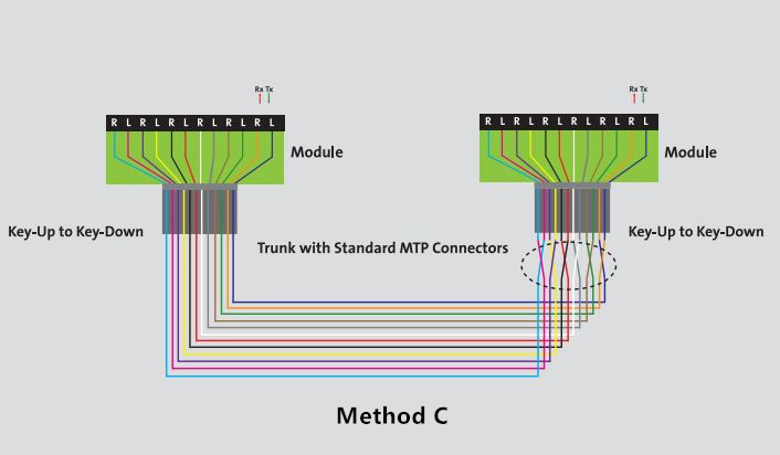
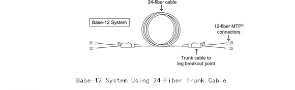
Base-2 connectivity is the most commonly used one in the past, but as the data center grew to thousands of fiber ports engaged, stringing two-fiber patch cords across all corners of the data center will result in an unmanageable, and unreliable mess. So Base-12 connectivity is introduced. It is designed to develop a modular, high density, structured cabling system which could be deployed in data centers quickly, while also maximizing port densities within the rack space. In this connectivity method, all the fiber optic cables are based on an increment of 12 fiber, like 12-fiber or 24-fiber MTP trunk cable.

Base-12 system using a 24-fiber trunk cable

Base-8 Shines the Light

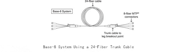
Base-12 connectivity is common in data center, but here comes a problem when installed it in a parallel system. For example, if we need to use 40GBase-SR4 optics implemented in a 12-fiber infrastructure, four fibers for transmit, and four fibers for receive, leaving four fibers unused per connection, this will lead to a significant and costly loss in fiber network utilization. But Base-8 can be a more cost-effective option for end-to-end MPO to MPO channels and architectures. With 8-fiber infrastructure, the 40GBase-SR4 module will use all the 8 fibers. Base-8 connectivity makes use of fiber links in increment of 8 versus 12. The 12-fiber trunk cables are replaced with trunk cables in increment of 8: 8-fiber, 16-fiber, or 24-fiber trunk cables, etc.

Base-8 system using a 24-fiber trunk cable

Can We Use Base-8 and Base-12 Together?

Although using Base-8 connectivity could decrease fiber consuming in supporting 40G data rates, in fact, in many cases, Base-8 connectivity isn’t a universal solution, and Base-12 may still be more cost-effective. So is it possible to have both Base-8 and Base-12 connectivity in the same data center? The answer could be “Yes” or “No”.

Base-8 and Base-12 Fiber Links Cannot Be Mixed and Matched

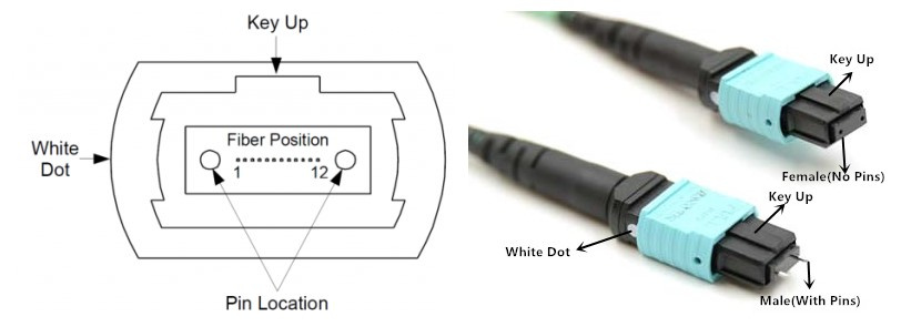
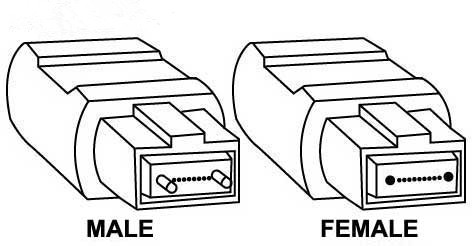
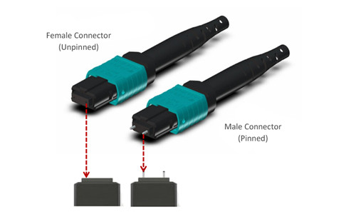
It is never possible to directly mix the components of Base-8 and Base-12 connectivity, or plug a Base-8 trunk into a 12-fiber module. Because a Base-12 trunk cable normally has unpinned MTP connector on both ends, and requires the use of pinned 12-fiber breakout modules, while a Base-8 trunk cable is manufactured with pinned MTP connectors at both ends (pinned and unpinned MTP connectors are shown below). So if we plug a Base-8 trunk into a 12-fiber breakout module, just like trying to mate two pinned connectors together, this connection will definitely not work, and vice verse.

pinned and unpinned MTP connector

Base-8 and Base-12 Can be Maintained in the Same Data Center Separately

It is possible to deploy both Base-8 and Base-12 connectivity within the same data center, just as long as the links are separate. Since Base-8 and Base-12 components are not interchangeable, during managing the data center physical layer infrastructure, we should do careful management and labeling practice to ensure we will not mix or mismatch them.

Conclusion

Base-12 connectivity has dominated the 40G network market for years, while the Base-8 connectivity is an additional option in the network designer’s tool kit to ensure that data centers have the most cost-effective, future-proof network available. When using Base-8 and Base-12 in network, make sure that you need to carefully manage and label them, and that the components in Base-8 and Base-12 won’t be mixed.

An Easy Guide to MPO/MTP Polarity

Nowadays, many data centers are migrating into the 40G and 100G transmission. To prepare for this change, MPO/MTP technology is applied to meet the requirements of high density patching. Typically, a fiber optic link needs two fibers for full duplex communications. Thus the equipment on the link should be connected properly at each end. However, high density connectivity usually requires more than two fibers in a link, which makes it more complex to maintain the correct polarity across a fiber network, especially when using multi-fiber MPO/MTP components for high data rate transmission. Therefore, many technicians would prefer to use pre-terminated MPO/MTP components designed with polarity maintenance for easier installation. This article will specifically guide you to understand the polarity of MPO/MTP products and the common polarization connectivity solutions.

What Is Polarity?

Keeping the right polarity is essential to the network. A transmit signal from any type of active equipment will be directed to the receive port of a second piece of active equipment and vice versa. Polarity is the term used in the TIA-568 standard to explain how to make sure each transmitter is correctly connected to a receiver on the other end of a multi-fiber cable. Once the component is connected to the wrong polarity, the transmission process will be unable to go on.

Structure of MPO/MTP Connector

When discussing about the polarity, MPO/MTP connector is an important component for you to know. An MPO/MTP connector has a key on one side of the connector body. There are two positions of the key – key up or key down. Key up position means that the key sits on top. When the key sits on the bottom, it is the key down position. Moreover, the fiber holes in the connector are numbered in sequence from left to right named as P1 (position 1), P2, etc. Each connector is additionally marked with a white dot on the connector body to designate the P1 side of the connector when it is plugged in. The MPO/MTP connector can be further divided into female connector and male connector. The former has no pins while the latter has two pins on the connector. The following picture shows the basic structure of MPO/MTP connector.

structure-of-mpo-connector

Connecting Methods of A, B, C

The TIA standard defines two types of duplex fiber patch cables terminated with LC or SC connectors to complete an end-to-end fiber duplex connection: A-to-A type patch cable is a cross version and A-to-B type patch cable is a straight-through version. Based on this, there are three polarity connecting methods for MPO/MTP products. Here will introduce them in details.

duplex-patch-cable

Method A is the most straight-forward method. It uses straight-through patch cords (A-to-B) on one end that connect through a cassette (LC-to-MPO or SC-to-MPO depends on what the equipment connector is), a straight-through MPO/MTP key up to key down backbone cable and a “cross-over” patch cord (A-to-A) at the other end.

method-a

Method B is the “cross-over” occurred in the cassette. The keys on the MPO cable connectors are in an up position at both ends, but the fiber that is at connector P1 in one end is in P12 at the opposite end, and the fiber that is in P12 at the originating end is in P1 at the opposing end. Only A-to-B type patch cord is needed for this method.

method-b

Method C is the most complicated. There is pair-wise “cross-over” in the backbone cable. A-to-B patch cords are used on both ends. The cassette uses MPO/MTP key up to key down and the backbone cable is pair-wise flipped so P1, P2 connects to P2, P1 and P3, P4 connects to P4, P3, etc.

method-c

Conclusion

Knowing the polarity of MPO/MTP system helps you better upgrade the 40G and 100G networks. According to different polarity methods, choosing the right MPO/MTP patch cables , connectors and cassettes will provide greater flexibility and reliability for your high density network.

MPO/MTP Connector – Multi-fiber Connector for High Port Density

In today’s transmission networks, small and multi-fiber connectors are replacing larger, older styles connectors for space saving. For example, the SC connector is gradually being replaced by its small version LC connector which allows more fiber ports per unit of rack space. To save space, multi-fiber connector is also a good solution, like MTP/MPO connectors. MTP/MPO connector allows more fiber ports per unit of rack space and also satisfies parallel optical interconnections’ needs for multi-fiber connection. This article is to introduce MPO/MTP connectors in details.

MPO Connector & MTP Connector

MT ferrule

MPO is short for the industry acronym—”multi-fiber push on”. The MPO connector is a multi-fiber connector which is most commonly defined by two documents: IEC-61754-7 (the commonly sited standard for MPO connectors internationally) and EIA/TIA-604-5 (also known as FOCIS 5, is the most common standard sited for in the US). MPO connectors are based on MT ferrule (showed in the picture on the right) which can provide quick and reliable high performance interconnections up to 4, 12, 24 or more and are usually used with ribbon fiber cables. The following picture shows diagram of MPO connectors, 12-fold (left) and 24-fold (right). The fibers for sending and receiving are colorcoded, red and green, respectively.

mpo-mtp-connector-fiber-count

MTP stands for “Multi-fiber Termination Push-on” connector and it is designed by USConec and built around the MT ferrule. MTP connector is a high performance MPO connector designated for better mechanical and optical performance and is in complete compliance with all MPO connector standards. Some main improvements of MTP connector are as following:

  • The MTP connector housing is removable;
  • The MTP connector offers ferrule float to improve mechanical performance;
  • The MTP connector uses tightly held tolerance stainless steel guide pin tips with an elliptical shape;
  • The MTP connector has a metal pin clamp with features for centering the push spring;
  • The MTP connector spring design maximizes ribbon clearance for twelve fiber and multifiber ribbon applications to prevent fiber damage;
  • The MTP connector is offered with four standard variations of strain relief boots to meet a wide array of applications.
Application of MPO/MTP Connector

As mentioned, MPO/MPT connectors are compatible ribbon fiber connectors. MPO/MTP connectors cannot be field terminated, thus MTP/MPO connector is usually assembled with fiber optic cable. MTP/MPO fiber optic cable is one of the most popular MTP/MPO fiber optic cable assemblies, which are now being widely used in data center to provide quick and reliable operation during signal transmission. MPO/MTP connectors can be found in the following applications:

  • Gigabit Ethernet
  • CATV and Multimedia
  • Active Device Interface
  • Premise installations
  • Optical Switch interframe connections
  • Interconnection for O/E modules
  • Telecommunication Networks
  • Industrial & Medical, etc.
MPO/MTP Connector Selection Guide

The structure of MPO/MTP connector is a little complicated. The picture below shows the components of a MPO connector.

MPO connector components

With the drive of market requests. Various types of MPO/MTP connectors are being provided. Some basic aspects should be considered during the selection of a MPO/MTP connector are as following:

mtp-mpo-connector-male-female

First is pin option. MPO/MTP connectors have male and female design (as showed in the picture on the left). Male connectors have two guide pins and female connectors do not. Alignment between mating ferrules of MPO/MTP connectors is accomplished using two precision guide pins that are pre-installed into the designated male connector. Second is fiber count: MPO/MTP connector could provide 4, 6, 8, 12, 24, 36, 64 or more interconnections, among which 12 and 24 are the most popular MPO/MTP connectors. In addition, like other fiber optic connectors, the selection of a MPO/MTP connectors should also consider fiber type and simplex or duplex design.

MPO/MTP Connector is a popular multi-fiber connector for high port density. It can offer ideal solution to set up high-performance data networks with the advantages of time saving and cost saving. As an important technology during migration to 40/100 Gigabit Ethernet, MTP/MPO connector is now being adopted by more and more data centers.