An Easy Guide to MPO/MTP Polarity

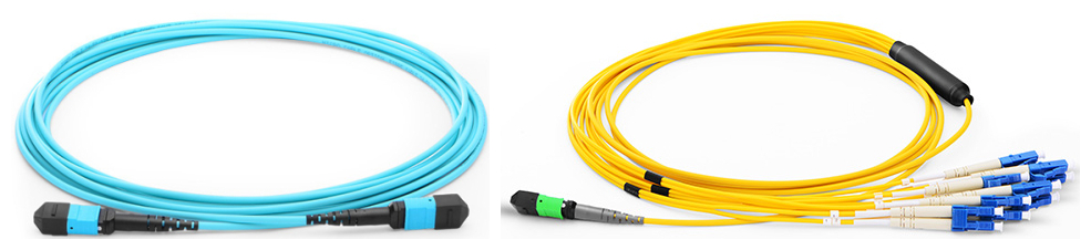
Nowadays, many data centers are migrating into the 40G and 100G transmission. To prepare for this change, MPO/MTP technology is applied to meet the requirements of high density patching. Typically, a fiber optic link needs two fibers for full duplex communications. Thus the equipment on the link should be connected properly at each end. However, high density connectivity usually requires more than two fibers in a link, which makes it more complex to maintain the correct polarity across a fiber network, especially when using multi-fiber MPO/MTP components for high data rate transmission. Therefore, many technicians would prefer to use pre-terminated MPO/MTP components designed with polarity maintenance for easier installation. This article will specifically guide you to understand the polarity of MPO/MTP products and the common polarization connectivity solutions.

What Is Polarity?

Keeping the right polarity is essential to the network. A transmit signal from any type of active equipment will be directed to the receive port of a second piece of active equipment and vice versa. Polarity is the term used in the TIA-568 standard to explain how to make sure each transmitter is correctly connected to a receiver on the other end of a multi-fiber cable. Once the component is connected to the wrong polarity, the transmission process will be unable to go on.

Structure of MPO/MTP Connector

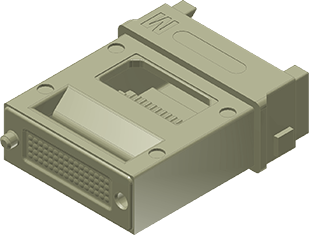
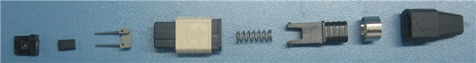
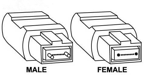
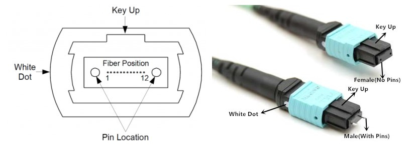
When discussing about the polarity, MPO/MTP connector is an important component for you to know. An MPO/MTP connector has a key on one side of the connector body. There are two positions of the key – key up or key down. Key up position means that the key sits on top. When the key sits on the bottom, it is the key down position. Moreover, the fiber holes in the connector are numbered in sequence from left to right named as P1 (position 1), P2, etc. Each connector is additionally marked with a white dot on the connector body to designate the P1 side of the connector when it is plugged in. The MPO/MTP connector can be further divided into female connector and male connector. The former has no pins while the latter has two pins on the connector. The following picture shows the basic structure of MPO/MTP connector.

structure-of-mpo-connector

Connecting Methods of A, B, C

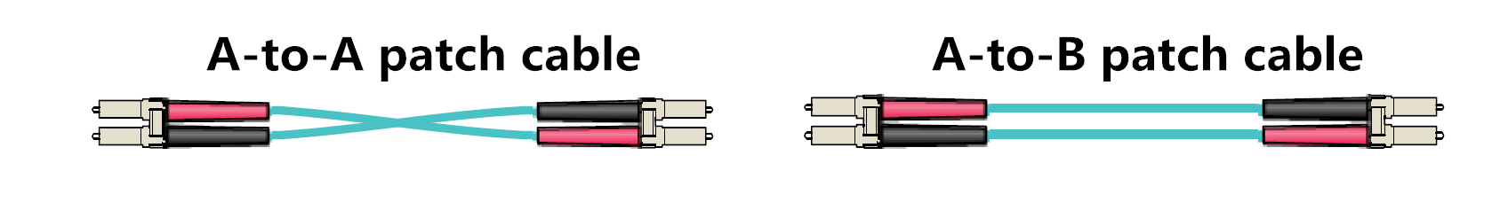
The TIA standard defines two types of duplex fiber patch cables terminated with LC or SC connectors to complete an end-to-end fiber duplex connection: A-to-A type patch cable is a cross version and A-to-B type patch cable is a straight-through version. Based on this, there are three polarity connecting methods for MPO/MTP products. Here will introduce them in details.

duplex-patch-cable

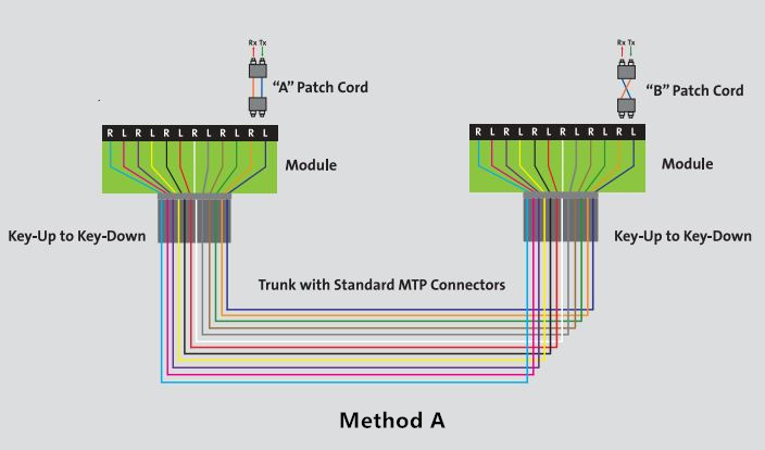
Method A is the most straight-forward method. It uses straight-through patch cords (A-to-B) on one end that connect through a cassette (LC-to-MPO or SC-to-MPO depends on what the equipment connector is), a straight-through MPO/MTP key up to key down backbone cable and a “cross-over” patch cord (A-to-A) at the other end.

method-a

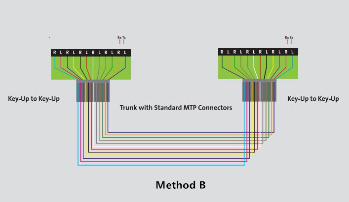
Method B is the “cross-over” occurred in the cassette. The keys on the MPO cable connectors are in an up position at both ends, but the fiber that is at connector P1 in one end is in P12 at the opposite end, and the fiber that is in P12 at the originating end is in P1 at the opposing end. Only A-to-B type patch cord is needed for this method.

method-b

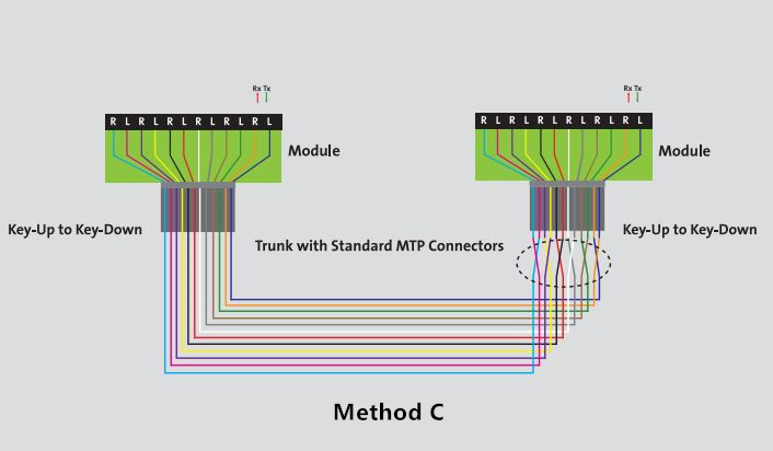
Method C is the most complicated. There is pair-wise “cross-over” in the backbone cable. A-to-B patch cords are used on both ends. The cassette uses MPO/MTP key up to key down and the backbone cable is pair-wise flipped so P1, P2 connects to P2, P1 and P3, P4 connects to P4, P3, etc.

method-c

Conclusion

Knowing the polarity of MPO/MTP system helps you better upgrade the 40G and 100G networks. According to different polarity methods, choosing the right MPO/MTP patch cables , connectors and cassettes will provide greater flexibility and reliability for your high density network.

MTP/MPO – An Easier Solution for High Density Patching

With the continuing growth of data throughput in networking, 40G network now becomes the commonplace and 100G has also been used increasing widespread. To achieve a higher transmission data rate, it is important to find a suitable solution for the high density cable routing. Thus, the arrival of MTP/MPO connection standard is a piece of good news for high density patching. The MTP/MPO technology is available with multi-fiber connectors which is a perfect solution for high-performance data transmission. There are a lot of benefits when adopting the MTP/MPO structure. This article will provide some effective MTP/MPO assemblies that are frequently used to meet high density demands.

Superiority of MPO/MTP Assemblies

Actual practice proves that MPO/MTP components are superior to other assemblies in high density applications. They can connect to equipment with various date rates of 10 Gbps, 40 Gbps or 100 Gbps, which makes them more flexible for the devices. Also, their installation is very simple. No tools are required to install the cassette in the panel enclosure, and the push-pull connection offers an easier way to be locked or unlocked in patch panels. Owing to the modular cassette system, they are also pretty adjustable in network reconfiguration. You may think this must cost you a great deal, however, the initial investment is very cost-effective.

Recommended MPO/MTP Products

Here are some recommended MPO/MTP products for high density patching. Using these assemblies can achieve a significant progress in operations.

1) MTP/MPO Cables

MTP/MPO cables consist of MTP/MPO connectors and fiber cables. Sometimes, other types of connector can also be linked to one termination. The fiber cables are usually employing OM3 or OM4 laser optimized multimode optical fibers. MTP/MPO trunk cables, harness/breakout cables and direct pigtails are three categories of MTP/MPO cables. The MTP/MPO trunk cables are available with 8, 12, 24, 36, 48, 72 and 144 fibers for single-mode and multimode applications. The harness/breakout cables is designed to work from trunk backbone assemblies to fiber rack system in the high density cabling. One end is terminated with a MTP/MPO connector, and the other end can have other options of connectors such as LC/SC/ST/MTRJ. The MTP/MPO pigtail cables are typically used for splicing directly inside fiber management panels near adapter ends.

mtp-mpo-cable

Appropriate utilization of MTP/MPO cassettes can help reduce installation time and investment for an optical network infrastructure in the premises. Rapid deployment of high density data center infrastructure can also be realized thanks to the modular system. The MTP/MPO plug-n-play cassette provides the interconnection between MTP/MPO backbones with LC/SC/ST/FC patching. Other recommended cassettes are 1U 19” rack mount cassettes holders, 4U 19” rack mount cassettes holders and 144 ports ultra HD angled patch panel. 1U 19” rack mount enclosure is integrated with three pieces of plug-n-play cassettes for up to 72 fibers patching. 4U 19” rack mount enclosure has 12 plug-n-play cassette pieces with 288 fibers patching. 144 ports ultra high density cassette is equipped with 72 LC duplex adapters for 144 fibers patching.

mtp-mpo-cassettes

3) MTP/MPO Optical Adapter & Adapter Panels

The black colored MTP/MPO adapter has two types as key-up to key-down and key-up to key-up. It provides the connection between cable to cable or cable to equipment in the MTP/MPO style. The MTP/MPO fiber adapter panels are available with 2, 3, 4, 6, 8, 12, 16 and 18 ports both horizontally and vertically in lighter package.

mtp-mpo-optcial-adapter-and-adapter-panels

Conclusion

In summary, if you need devices for high density deployment, MTP/MPO assemblies are absolutely best solutions. Applying the MTP/MPO connection, its patch cables, cassettes and adapters will be promoted to a more effective use.

MPO/MTP Connector – Multi-fiber Connector for High Port Density

In today’s transmission networks, small and multi-fiber connectors are replacing larger, older styles connectors for space saving. For example, the SC connector is gradually being replaced by its small version LC connector which allows more fiber ports per unit of rack space. To save space, multi-fiber connector is also a good solution, like MTP/MPO connectors. MTP/MPO connector allows more fiber ports per unit of rack space and also satisfies parallel optical interconnections’ needs for multi-fiber connection. This article is to introduce MPO/MTP connectors in details.

MPO Connector & MTP Connector

MT ferrule

MPO is short for the industry acronym—”multi-fiber push on”. The MPO connector is a multi-fiber connector which is most commonly defined by two documents: IEC-61754-7 (the commonly sited standard for MPO connectors internationally) and EIA/TIA-604-5 (also known as FOCIS 5, is the most common standard sited for in the US). MPO connectors are based on MT ferrule (showed in the picture on the right) which can provide quick and reliable high performance interconnections up to 4, 12, 24 or more and are usually used with ribbon fiber cables. The following picture shows diagram of MPO connectors, 12-fold (left) and 24-fold (right). The fibers for sending and receiving are colorcoded, red and green, respectively.

mpo-mtp-connector-fiber-count

MTP stands for “Multi-fiber Termination Push-on” connector and it is designed by USConec and built around the MT ferrule. MTP connector is a high performance MPO connector designated for better mechanical and optical performance and is in complete compliance with all MPO connector standards. Some main improvements of MTP connector are as following:

  • The MTP connector housing is removable;
  • The MTP connector offers ferrule float to improve mechanical performance;
  • The MTP connector uses tightly held tolerance stainless steel guide pin tips with an elliptical shape;
  • The MTP connector has a metal pin clamp with features for centering the push spring;
  • The MTP connector spring design maximizes ribbon clearance for twelve fiber and multifiber ribbon applications to prevent fiber damage;
  • The MTP connector is offered with four standard variations of strain relief boots to meet a wide array of applications.
Application of MPO/MTP Connector

As mentioned, MPO/MPT connectors are compatible ribbon fiber connectors. MPO/MTP connectors cannot be field terminated, thus MTP/MPO connector is usually assembled with fiber optic cable. MTP/MPO fiber optic cable is one of the most popular MTP/MPO fiber optic cable assemblies, which are now being widely used in data center to provide quick and reliable operation during signal transmission. MPO/MTP connectors can be found in the following applications:

  • Gigabit Ethernet
  • CATV and Multimedia
  • Active Device Interface
  • Premise installations
  • Optical Switch interframe connections
  • Interconnection for O/E modules
  • Telecommunication Networks
  • Industrial & Medical, etc.
MPO/MTP Connector Selection Guide

The structure of MPO/MTP connector is a little complicated. The picture below shows the components of a MPO connector.

MPO connector components

With the drive of market requests. Various types of MPO/MTP connectors are being provided. Some basic aspects should be considered during the selection of a MPO/MTP connector are as following:

mtp-mpo-connector-male-female

First is pin option. MPO/MTP connectors have male and female design (as showed in the picture on the left). Male connectors have two guide pins and female connectors do not. Alignment between mating ferrules of MPO/MTP connectors is accomplished using two precision guide pins that are pre-installed into the designated male connector. Second is fiber count: MPO/MTP connector could provide 4, 6, 8, 12, 24, 36, 64 or more interconnections, among which 12 and 24 are the most popular MPO/MTP connectors. In addition, like other fiber optic connectors, the selection of a MPO/MTP connectors should also consider fiber type and simplex or duplex design.

MPO/MTP Connector is a popular multi-fiber connector for high port density. It can offer ideal solution to set up high-performance data networks with the advantages of time saving and cost saving. As an important technology during migration to 40/100 Gigabit Ethernet, MTP/MPO connector is now being adopted by more and more data centers.