Hyperconverged Infrastructure: Maximizing IT Efficiency

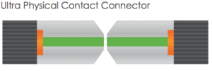
In the ever-evolving world of IT infrastructure, the adoption of hyperconverged infrastructure (HCI) has emerged as a transformative solution for businesses seeking efficiency, scalability, and simplified management. This article delves into the realm of HCI, exploring its definition, advantages, its impact on data centers, and recommendations for the best infrastructure switch for small and medium-sized businesses (SMBs).

What Is Hyperconverged Infrastructure?

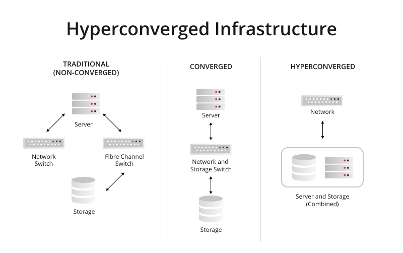
Hyperconverged infrastructure (HCI) is a type of software-defined infrastructure that tightly integrates compute, storage, networking, and virtualization resources into a unified platform. Unlike traditional data center architectures with separate silos for each component, HCI converges these elements into a single, software-defined infrastructure. HCI’s operation revolves around the integration of components, software-defined management, virtualization, scalability, and efficient resource utilization to create a more streamlined, agile, and easier-to-manage infrastructure compared to traditional heterogeneous architectures.

Hyperconverged Infrastructure

Benefits of Hyperconverged Infrastructure

Hyperconverged infrastructure (HCI) offers several benefits that make it an attractive option for modern IT environments:

Simplified Management: HCI consolidates various components (compute, storage, networking) into a single, unified platform, making it easier to manage through a single interface. This simplifies administrative tasks, reduces complexity, and saves time in deploying, managing, and scaling infrastructure.

Scalability: It enables seamless scalability by allowing organizations to add nodes or resources independently, providing flexibility in meeting changing demands without disrupting operations.

Cost-Efficiency: HCI often reduces overall costs compared to traditional infrastructure by consolidating hardware, decreasing the need for specialized skills, and minimizing the hardware footprint. It also optimizes resource utilization, reducing wasted capacity.

Increased Agility: The agility provided by HCI allows for faster deployment of resources and applications. This agility is crucial in modern IT environments where rapid adaptation to changing business needs is essential.

Better Performance: By utilizing modern software-defined technologies and optimizing resource utilization, HCI can often deliver better performance compared to traditional setups.

Resilience and High Availability: Many HCI solutions include built-in redundancy and data protection features, ensuring high availability and resilience against hardware failures or disruptions.

Simplified Disaster Recovery: HCI simplifies disaster recovery planning and implementation through features like data replication, snapshots, and backup capabilities, making it easier to recover from unexpected events.

Support for Virtualized Environments: HCI is well-suited for virtualized environments, providing a robust platform for running virtual machines (VMs) and containers, which are essential for modern IT workloads.

Best Hyperconverged Infrastructure Switch for SMBs

The complexity of traditional data center infrastructure, both hardware and software, poses challenges for SMBs to manage independently, resulting in additional expenses for professional services for setup and deployment. However, the emergence of hyperconverged infrastructure (HCI) has altered this landscape significantly. HCI proves highly beneficial and exceedingly suitable for the majority of SMBs. To cater for the unique demands for hyper-converged appliance, FS.com develops the S5800-8TF12S 10gb switch which is particularly aimed at solving the problems of access to the hyper-converged appliance of small and medium-sized business. With the abundant benefits below, it is a preferred key solution for the connectivity between hyper-converged appliance and the core switch.

Data Center Grade Hardware Design

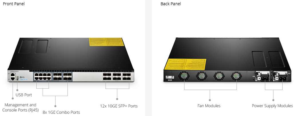
FS S5800-8TF12S hyper-converged infrastructure switch provides high availability port with 8-port 1GbE RJ45 combo, 8-port 1GbE SFP combo and 12-port 10GbE uplink in a compact 1RU form factor. With the capability of static link aggregation and integrated high performance smart buffer memory, it is a cost-effective Ethernet access platform to hyper-converged appliance.

FS Switch

Reduced Power Consumption

With two redundant power supply units and four smart built-in cooling fans, FS S5800-8TF12S hyper-converged infrastructure switch provides necessary redundancy for the switching system, which ensures optimal and secure performance. The redundant power supplies can maximize the availability of the switching device. The heat sensors on the fan control PCBA (Printed Circuit Board Assembly) monitor and detect the ambient airs. It converts fans speeds accordingly to adapt to the different temperatures, thus reducing power consumption in proper operating temperatures.

Multiple Smart Management

Instead of being managed by Web interface, the FS S5800-8TF12S hyper-converged infrastructure switch supports multiple smart management with two RJ45 management and console ports. SNMP (Simple Network Management Protocol) is also supported by this switch. Thus when managing several switches in a network, it is possible to make the changes automatically to all switches. What about the common switches managed only by Web interface? It will be a nightmare when an SMB needs to configure multiple switches in the network, because there’s no way to script the push out of changes if not parse the web pages.

Traffic Visibility and Trouble-Shooting

In FS S5800-8TF12S HCI switch, the traffic classification is based on the combination of the MAC address, IPv4/IPv6 address, L2 protocol header, TCP/UDP, outgoing interface, and 802.1p field. The traffic shaping is based on interfaces and queues. Thus the traffic flow which are visible and can be monitored in real time. With the DSCP remarking, the video and voice traffic that is sensitive to network delays can be prioritized over other data traffic, so the smooth video streaming and reliable VoIP calls are ensured. Besides, the FS S5800-8TF12S switch comes with comprehensive functions that can help in trouble-shooting. Some basic functions include Ping, Traceroute, Link Layer Discovery Protocol (LLDP), Syslog, Trap, Online Diagnostics and Debug.

Conclusion

Hyperconverged infrastructure stands as a catalyst for IT transformation, offering businesses a potent solution to optimize efficiency, streamline operations, and adapt to ever-changing demands. By embracing HCI and selecting the right infrastructure components, SMBs can harness the power of integrated systems to drive innovation and propel their businesses forward in today’s dynamic digital landscape.

What Is FCoE and How Does It Work?

In the rapidly evolving landscape of networking technologies, one term gaining prominence is FCoE, or Fibre Channel over Ethernet. As businesses seek more efficient and cost-effective solutions, understanding the intricacies of FCoE becomes crucial. This article delves into the world of FCoE, exploring its definition, historical context, and key components to provide a comprehensive understanding of how it works.

What is FCoE (Fibre Channel over Ethernet)?

  • In-Depth Definition

Fibre Channel over Ethernet, or FCoE, is a networking protocol that enables the convergence of traditional Fibre Channel storage networks with Ethernet-based data networks. This convergence is aimed at streamlining infrastructure, reducing costs, and enhancing overall network efficiency.

  • Historical Context

The development of FCoE can be traced back to the need for a more unified and simplified networking environment. Traditionally, Fibre Channel and Ethernet operated as separate entities, each with its own set of protocols and infrastructure. FCoE emerged as a solution to bridge the gap between these two technologies, offering a more integrated and streamlined approach to data storage and transfer.

  • Key Components

At its core, FCoE is a fusion of Fibre Channel and Ethernet technologies. The key components include Converged Network Adapters (CNAs), which allow for the transmission of both Fibre Channel and Ethernet traffic over a single network link. Additionally, FCoE employs a specific protocol stack that facilitates the encapsulation and transport of Fibre Channel frames within Ethernet frames.

How does Fibre Channel over Ethernet Work?

  • Convergence of Fibre Channel and Ethernet

The fundamental principle behind FCoE is the convergence of Fibre Channel and Ethernet onto a shared network infrastructure. This convergence is achieved through the use of CNAs, specialized network interface cards that support both Fibre Channel and Ethernet protocols. By consolidating these technologies, FCoE eliminates the need for separate networks, reducing complexity and improving resource utilization.

  • Protocol Stack Overview

FCoE utilizes a layered protocol stack to encapsulate Fibre Channel frames within Ethernet frames. This stack includes the Fibre Channel over Ethernet Initialization Protocol (FIP), which plays a crucial role in the discovery and initialization of FCoE-capable devices. The encapsulation process allows Fibre Channel traffic to traverse Ethernet networks seamlessly.

  • FCoE vs. Traditional Fibre Channel

Comparing FCoE with traditional Fibre Channel reveals distinctive differences in their approaches to data networking. While traditional Fibre Channel relies on dedicated storage area networks (SANs), FCoE leverages Ethernet networks for both data and storage traffic. This fundamental shift impacts factors such as infrastructure complexity, cost, and overall network design.


” Also Check – IP SAN (IP Storage Area Network) vs. FCoE (Fibre Channel over Ethernet) | FS Community

What are the Advantages of Fibre Channel over Ethernet?

  1. Enhanced Network Efficiency

FCoE optimizes network efficiency by combining storage and data traffic on a single network. This consolidation reduces the overall network complexity and enhances the utilization of available resources, leading to improved performance and reduced bottlenecks.

  1. Cost Savings

One of the primary advantages of FCoE is the potential for cost savings. By converging Fibre Channel and Ethernet, organizations can eliminate the need for separate infrastructure and associated maintenance costs. This not only reduces capital expenses but also streamlines operational processes.

  1. Scalability and Flexibility

FCoE provides organizations with the scalability and flexibility needed in dynamic IT environments. The ability to seamlessly integrate new devices and technologies into the network allows for future expansion without the constraints of traditional networking approaches.

Conclusion

In conclusion, FCoE stands as a transformative technology that bridges the gap between Fibre Channel and Ethernet, offering enhanced efficiency, cost savings, and flexibility in network design. As businesses navigate the complexities of modern networking, understanding FCoE becomes essential for those seeking a streamlined and future-ready infrastructure.


Related Articles: Demystifying IP SAN: A Comprehensive Guide to Internet Protocol Storage Area Networks

What Is Network Edge?

The concept of the network edge has gained prominence with the rise of edge computing, which involves processing data closer to the source of data generation rather than relying solely on centralized cloud servers. This approach can reduce latency, improve efficiency, and enhance the overall performance of applications and services. In this article, we’ll introduce what the network edge is, explore how it differs from edge computing, and describe the benefits that network edge brings to enterprise data environments.

What is Network Edge?

At its essence, the network edge represents the outer periphery of a network. It’s the gateway where end-user devices, local networks, and peripheral devices connect to the broader infrastructure, such as the internet. It’s the point at which a user or device accesses the network or the point where data leaves the network to reach its destination. the network edge is the boundary between a local network and the broader network infrastructure, and it plays a crucial role in data transmission and connectivity, especially in the context of emerging technologies like edge computing.

What is Edge Computing and How Does It Differ from Network Edge?

The terms “network edge” and “edge computing” are related concepts, but they refer to different aspects of the technology landscape.

What is Edge Computing?

Edge computing is a distributed computing paradigm that involves processing data near the source of data generation rather than relying on a centralized cloud-based system. In traditional computing architectures, data is typically sent to a centralized data center or cloud for processing and analysis. However, with edge computing, the processing is performed closer to the “edge” of the network, where the data is generated. Edge computing complements traditional cloud computing by extending computational capabilities to the edge of the network, offering a more distributed and responsive infrastructure.

” Also Check – What Is Edge Computing?

What is the Difference Between Edge Computing and Network Edge?

While the network edge and edge computing share a proximity in their focus on the periphery of the network, they address distinct aspects of the technological landscape. The network edge is primarily concerned with connectivity and access, and it doesn’t specifically imply data processing or computation. Edge computing often leverages the network edge to achieve distributed computing, low-latency processing and efficient utilization of resources for tasks such as data analysis, decision-making, and real-time response.

Network Edge vs. Edge Computing

Network Edge vs. Network Core: What’s the Difference?

Another common source of confusion is discerning the difference between the network edge and the network core.

What is Network Core?

The network core, also known as the backbone network, is the central part of a telecommunications network that provides the primary pathway for data traffic. It serves as the main infrastructure for transmitting data between different network segments, such as from one city to another or between major data centers. The network core is responsible for long-distance, high-capacity data transport, ensuring that information can flow efficiently across the entire network.

What is the Difference between the Network Edge and the Network Core?

The network edge is where end-users and local networks connect to the broader infrastructure, and edge computing involves processing data closer to the source, the network core is the backbone that facilitates the long-distance transmission of data between different edges, locations, or network segments. It is a critical component in the architecture of large-scale telecommunications and internet systems.

Advantages of Network Edge in Enterprise Data Environments

Let’s turn our attention to the practical implications of edge networking in enterprise data environments.

Efficient IoT Deployments

In the realm of the Internet of Things (IoT), where devices generate copious amounts of data, edge networking shines. It optimizes the processing of IoT data locally, reducing the load on central servers and improving overall efficiency.

Improved Application Performance

Edge networking enhances the performance of applications by processing data closer to the point of use. This results in faster application response times, contributing to improved user satisfaction and productivity.

Enhanced Reliability

Edge networks are designed for resilience. Even if connectivity to the central cloud is lost, local processing and communication at the edge can continue to operate independently, ensuring continuous availability of critical services.

Reduced Network Costs

Local processing in edge networks diminishes the need for transmitting large volumes of data over the network. This not only optimizes bandwidth usage but also contributes to cost savings in network infrastructure.

Privacy and Security

Some sensitive data can be processed locally at the edge, addressing privacy and security concerns by minimizing the transmission of sensitive information over the network. Improved data privacy and security compliance, especially in industries with stringent regulations.

In this era of digital transformation, the network edge stands as a gateway to a more connected, efficient, and responsive future.

Related Articles:

How Does Edge Switch Make an Importance in Edge Network?

How to Use an Ethernet Switch?

For many household use, it is common to see just a modem and a router. That’s enough for most family network requirements. However, if you have too many computers to manage, an Ethernet switch is definitely what you need. Since network switch is not prevalent in ordinary homes, many people don’t have a clear understanding of it, let alone its usage. Here we will figure out what is an Ethernet switch used for and how to use and Ethernet switch.

What Is an Ethernet Switch?

An Ethernet switch is a network device used to connect different PCs, servers, laptops or other Ethernet devices to a local area network. In this way, the connected devices can communicate with each other. The switch utilizes an MAC access table to exchange data packets among these devices.
Network switches come in many types. Different switches have different applications and functions. They may come in 16, 32 or 64 ports, and also in various port speeds. The basic speed is 10 megabit per second, then 100 megabit. And today we also have faster gigabit Ethernet switch which realizes 1000 megabits per second. Switches that contain more ports or higher speeds are suitable for more demanding conditions.

What Is an Ethernet Switch Used for?

The Ethernet switch plays an integral role in most modern Ethernet local area networks (LANs). Here introduces two switch types for different utilities. The one is the fool-proof unmanaged Ethernet switch and the other is the intelligent managed switch.

Unmanaged Ethernet Switch for Small Size Environment

Unmanaged switches simply allow Ethernet devices to communicate with one another by providing a connection to the network. Unmanaged switches are truly plug and play devices. However, this simplicity of unmanaged Ethernet switches also limits the functionality of a network. Therefore, unmanaged switches are usually used for small size environments like home where the applications are relatively few and simplified.

Managed Ethernet Switch for Data Center

Managed switch is more advanced than unmanaged switch as it not only possesses what the latter features with, but also can be configured and properly managed to offer a more tailored experience. Most managed switches are 10gbe Ethernet switch, 40gbe, 100gbe or much faster switches. Those can be deployed in large data center, server rooms and so on.

How to Use an Ethernet Switch?

Whether it is the unmanaged switch or managed switch, the usage remains essentially the same. It should initially access the network and the power supply. This part introduces using an Ethernet switch.

First, connect modem to Ethernet input line. Modem is the device that brings the signal into the network.

Second, connect router to modem. Router translates the private network address into public address so as to entitle all the connected network devices to the Internet.

Third, connect an Ethernet cable to one port on the switch, then connect the other end to a wired device such as a computer. Repeat this step to connect all PCs, servers, laptops or other Ethernet devices.

Fourth, connect an Ethernet cable to one of the ports at the back of the switch, then connect the other end of the cable to one of the Ethernet ports at the back of the router. The switch is thus becoming the extension of the router. You plug in one output to your router, and the other ones will just split up that connection to give you more hookups.

Fifth, connect the supplied power adapter to the power port on the switch, then connect the other end into a power socket. This step can be omitted if it is a PoE switch.

Ethernet switch setup diagram

Fig 1. Ethernet switch setup diagram

Having finished the connection, the unmanaged switch is ready to go while the managed switch may require further adjustments through a supported method, whether it is a command line interface (accessed via secure shell, etc.), a web interface loaded in your web browser or Simple Network Management Protocol (SNMP) for remote access. This approach will unleash various options, including port speed, virtual LANs, redundancy, port mirroring, and Quality of Service (QoS) for traffic prioritization.

Conclusion

This article introduces Ethernet switch and illustrates how to use an it. Ethernet switch is basically regarded as the port extension of the router, and also grows with more functions as the network expands. As for the issue—how to use an Ethernet switch with router, please read the post “Network Switch Before or After Router”.

How to Select Waterproof Fiber Optic Patch Cable?

Fiber optic waterproof cables are widely used in outdoor applications to connect the major fiber optic lines or receivers or splice enclosures. According to different requirements, both fiber optic patch cords and fiber optic pigtails are available. Water proof fiber cable usually adds a water blocking material between the outer jacket and the inner fiber (or inner jacket) to protect the fiber surface from unwanted damage, such as an armored cable or loose-tube gel-filled cable, or water-tolerable tight-buffered cable. Since there are different types of structure for waterproof cables, is there an easy way to determine which waterproof fiber optic patch cable to choose? In order to help select a right waterproof fiber optic cable quickly, this post will introduce the basic knowledge of waterproof ratings and the features of our waterproof fiber optic cable.

LC-LC waterproof fiber patch cable

How Is a Waterproof Cable Rated?

Like choosing any other fiber optic patch cables, the connector type, fiber count, fiber type (single-mode or multimode), polish type, cable length and cable jacket are factors that should be considered as well. When buying waterproof fiber optic patch cords, the IP (International Protection or Ingress Protection) rating is an important parameter. Knowing the IP code can help you find your wanted waterproof cable.

IP rating system is a classification showing the degrees of protection from solid objects and liquids. IP rating codes do not include hyphens or spaces, and consist of the letters IP followed by one or two figures. The first number refers to the degree of protection against the entry of foreign solid objects, such as dust. These protection levels range from 0 to 6. The second number of the IP code refers to the degrees of protection against moisture/liquids, which are raging from 0 to 8. The first and second number of the IP code can be replaced by the letter “X” when the protection capacity against solid objects (the first number) or moisture (the second number) has not been tested, for example, IPX7 and IP6X.

The following two tables explain the two types of protection levels in details.

Table 1: Protection levels against solid objects.

IP Code Protection Object Size
0 No protection. N/A
1 Protection from contact with any large surface of the body, such as the back of a hand, but no protection against deliberate contact with a body part, such as a finger. Less than 50mm.
2 Protection from fingers or similar objects. Less than 12.5mm.
3 Protection from tools, thick wires or similar objects. Less than 2.5mm.
4 Protection from most wires, screws or similar objects. Less than 1mm.
5 Partial protection from contact with harmful dust. N/A
6 Partial protection from contact with harmful dust. N/A

Table 2: Protection levels against moisture.

IP Code Protection Test Duration Usage
0 No protection. N/A N/A
1 Protection against vertically dripping water. 10 mins Light rain.
2 Protection against vertically dripping water when device is tilted at an angle up to 15 degrees. 10 mins Light rain.
3 Protection against direct sprays of water when device is tilted at an angle up to 60 degrees. 5 mins Rain and spraying.
4 Protection from sprays and splashing of water in all directions. 5 mins Rain, spraying and splashing.
5 Protection from low-pressure water projected from a nozzle with a 6.3mm diameter opening in any direction. 3 mins from a distance of 3 meters Rain, splashing and direct contact with most kitchen/bathroom faucets.
6 Protection from water projected in powerful jets from a nozzle with a 12.5mm diameter opening in any direction. 3 mins from a distance of 3 meters Rain, splashing, direct contact with kitchen/bathroom faucets, outdoor use in rough sea conditions.
7 Protected from immersion in water with a depth of up to 1 meter (or 3.3 feet) for up to 30 mins. 30 mins Rain, splashing and accidental submersion.
8 Protected from immersion in water with a depth of more than 1 meter (manufacturer must specify exact depth). Varies Rain, splashing and accidental submersion.
Features of FS.COM Waterproof Fiber Optic Patch Cable

FS.COM provides IP67 waterproof fiber optic patch cable, including simplex, duplex, 12 fibers, 24 fibers, and various kinds of connect interfaces are optional, such as LC-LC fiber patch cord, SC-SC fiber patch cord, MPO-MPO fiber patch cord, etc. Other degrees of waterproof fiber optic patch cords can also be customized. Our waterproof fiber patch cables are designed with strong PU jacket and armored structure, which can resist high temperature and fit for harsh environment. Our IP67 waterproof fiber patch cords are featured with high temperature stability and low insertion loss. It is also very convenient to install these waterproof, dust-proof and corrosion-resistant patch cords. The plug and socket design can be used to extend the cable length. They are very suitable for FTTH (fiber to the home) and LAN (local area network) applications.

Conclusion

The IP code for waterproof devices is not that difficult to understand and you can get some basic information about the protection degree of a device after you know the meaning of each number. You can use it as a reference in choosing a waterproof cable, but you should also consider other factors according to your specific applications.

Suggested 100G QSFP28 Transceiver Solutions for Data Centers

In recent years, QSFP28 transceiver module has upgraded the 100G market which can support the data transmission mode of 4×25G. Currently many data centers have already adopted QSFP28 transceiver for 100G migration. Of course, there are many other types of transceivers can transfer the 100G network, but QSFP28 modules are still considered to be the optimal choice. This post is going to present some useful 100G QSFP28 transceiver solutions for data centers. Maybe one of them is exactly what you need.

Basics of QSFP28 Transceiver

QSFP28 transceiver is designed for high-density and high-speed for applications in telecommunications. The transceiver offers four channels of different signals with data rates ranging from 25 Gbps up to potentially 40 Gbps, and meets 100 Gbps Ethernet (4×25 Gbps) and 100 Gbps 4X InfiniBand Enhanced Data Rate (EDR) requirements. QSFP28 optical transceiver has various advantages. It has a smaller size than other 100G modules, thus it is ideal for high-density ports on the switch. Power consumption of QSFP28 transceiver is usually the lowest of less than 3.5W. In addition, QSFP28 increases the transmission capacity of every lane from 10G to 25G, which can save much cost for each bit.

QSFP28 Transceiver Solutions

QSFP28 transceivers can be categorized into several types based on different IEEE (Institute of Electrical and Electronics Engineers ) or MSA (Multi-source Agreement) standards.

QSFP-100G-SR4 is the IEEE standard for 100G QSFP28 that supports short distance over multimode. It can reach 100G transmission up to 70m over OM3 and 100m over OM4. With the MTP/MPO interface, QSFP-100G-SR4 QSFP28 transceiver supports four lanes of 25G dual way transmission over eight fibers.

qsfp28 transceiver

QSFP-100G-LR4 is also the IEEE standard for QSFP28 module but supports long distance transmission for the maximum of 10km over single-mode fiber. QSFP-100G-LR4 is special for adopting the WDM technologies for four 25G lanes transmission over four different wavelengths. In addition, its duplex LC interface supports the 100G dual-way transmission.

qsfp28-lr4

100GBASE-PSM4 is the standard defined by MSA for the point-to-point 100G link over eight single-mode fibers reaching the length of up to 500m. 100GBASE-PSM4 QSFP28 transceiver uses four identical and independent lanes for each signal direction with each lane carrying a 25G optical transmission. With the MTP/MPO interface, optical fiber ribbon cables with MTP/MPO connectors can be plugged into the QSFP28 module.

qsfp28-psm4

100GBASE-CWDM4 standard was released by CWDM MSA to support 100G network for up to 2km. It uses the CWDM technology to reduce the transmission on 8 fibers (4 optical transmitters and four optical receivers) into 2 fibers. This transceiver is similar to QSFP-100G-LR4 but has a shorter transmission range and lower cost.

qsfp28-cwdm4

Conclusion

In a word, QSFP28 modules are suggested transceiver solutions for upgrading the data center 100G network. The QSFP-100G-SR4, QSFP-100G-LR4, 100GBASE-PSM4, and 100GBASE-CWDM4 QSFP28 transceivers mentioned above are the most popular ones to ensure the high-speed data transmission at either short or long distance. FS.COM offers both generic and compatible QSFP28 modules according to your demands. Other than QSFP28 transceivers, there are also many other types of 100G transceiver, such as CFP, CFP2, CFP4, CXP transceivers. For more information, please kindly visit FS.COM or contact us directly via sales@fs.com.

Fiber Optic Cable and Connector Selection

Proper selection of fiber optic cables and connectors for specific uses is becoming more and more important as fiber optic systems become the transmission medium for communications and aircraft applications, and even antenna links. Choices must be made in selecting fiber optic cables and connectors for high-reliability applications. This article provides the knowledge for how to make appropriate selections of fiber optic cable and connector when designing a fiber optic system.

Fiber Optic Cable Selection

To select a fiber optic cable, you have to make choices of both the fiber selection and the cable construction selection.

Fiber Selection

The three major fiber parameters used in selecting the proper fiber for an application are bandwidth, attenuation and core diameter.

Bandwidth: The bandwidth at a specified wavelength represents the highest sinusoidal light modulation frequency that can be transmitted through a length of fiber with an optical signal power loss equal to 50 percent of the zero modulation frequency component. The bandwidth is expressed in megahertz over a kilometer length (MHz/km).

Attenuation: The optical attenuation denotes the amount of optical power lost due to absorption and scattering of optical radiation at a specified wavelength in a length of fiber. It is expressed as an attenuation in decibels of optical power per kilometer (dB/km). The attenuation is determined by launching a narrow spectral band of light into the full length of fiber and measuring the transmitted intensity.

Core Diameter: The fiber core is the central region of an optical fiber whose refractive index is higher than that of the fiber cladding. Various core diameters are available to permit the most efficient coupling of light from commercially available light sources, such as laser diodes. There are two basic fiber types, single-mode and multimode. Single-mode fiber has a core diameter of 8 to 10 microns and is normally used for long distance requirements and high-bandwidth applications. Multimode fiber has a core diameter of 50 or 62.5 microns and is usually used in buildings. The picture below shows single-mode and multimode fiber with different core diameters.

multimode and singlemode fiber

Cable Construction Selection

Another important consideration when specifying optical fiber cable is the cable construction. There are three main types of cable configurations: buffered fiber cable, simplex cable and multichannel cable.

Buffered Fiber Cable: There are two kinds of buffered fiber. The first is a loose buffer tube construction where the fiber is contained in a water-blocked polymer tube that has an inner diameter considerably larger than the fiber itself. The loose buffer tube construction offers lower cable attenuation from a given fiber, and a high level of isolation from external forces. Loose buffer cables are typically used in outdoor applications and can accommodate the changes in external conditions. The second is a tight buffer tube design. A thick buffer coating is placed directly on the fiber. The tight buffer construction permits smaller, lighter weight designs and generally yields a more flexible cable. A comparison of these two cable constructions is shown below.

Buffered Fiber

Simplex Cable: A simplex fiber optic cable has only one tight buffered optical fiber inside the cable jackets. Simplex fiber optic cables are typically categorized as interconnect cables and are used to make interconnections in front of the patch panel. They are designed for production termination where consistency and uniformity are vital for fast and efficient operation.

Multichannel Cable: Building multiple fibers into one cable creates a multichannel cable. This type of cable is usually built with either a central or external strength member and fiber bundled around or within the strength member. An external jacket is used to keep the cable together.

Fiber Optic Connector Selection

Connector is an integral component of the cabling system infrastructure, which keeps the information flowing from cable to cable or cable to device. There are various connector types, including LC, FC, ST, SC, MTRJ, MPO, MTP, DIN, E2000, MU, etc. To design a fiber optic system, optical connector selection is also a very important decision. When selecting an optical connector, you have to take polishing styles, fiber types and number of fibers all into consideration.

Polishing Styles: There are mainly three kinds of polishing styles, PC (physical contact), APC (angled physical contact), and UPC (ultra physical contact). PC, UPC and APC refer to how the ferrule of the fiber optic connectors is polished. PC connector is used in many applications. UPC connectors are often used in digital, CATV, and telephony systems. APC connectors are preferred for CATV and analog systems. The picture below shows these three kinds of polishing styles.

Polish Types

Fiber Types: Single-mode and multi-mode optical fiber are two commonly used fiber types. Accordingly, there are single-mode optical connector and multi-mode optical connector. ST and MTRJ are the popular connectors for multi-mode networks. LC connector and SC connector are widely used in single-mode systems. Single-mode fiber optic connectors can be with PC, or UPC or APC polish, while multi-mode fiber optic connectors only with PC or UPC polish.

Number of Fibers: Simplex connector means only one fiber is terminated in the connector. Simplex connectors include FC, ST, SC, LC, MU and SMA. Duplex connector means two fibers are terminated in the connector. Duplex connectors include SC, LC, MU and MTRJ. Multiple fiber connector means more than two fibers are terminated in the connector. These are usually ribbon fibers with fiber count of 4, 6, 8, 12 and 24. The most popular ribbon fiber connector is MT connector.

Conclusion

The key to designing a successful fiber optic system is understanding the performance and applications of different kinds of fibers, cable constructions and optical connectors, and then utilizing the appropriate components. Fiberstore provides a wide range of fiber optic cables and connectors. Fiber optic cables can be available in single-mode, multimode, or polarization maintaining, and they can meet the strength and flexibility required for today’s fiber interconnect applications.

A Brief Introduction to PON

Optical fiber is reliable and cost-effective, therefore FTTx (fiber to the x) is widely used as a new generation of broadband solutions. How to implement FTTx? PON, passive optical network, is generally considered to be the best approach. The text will provide a basic introduction to PON.

PON Technologies

A passive optical network is a single, shared optical fiber that uses unpowered optical splitters to enable a single optical fiber to serve multiple end-points. PON is a point to multipoint (P2M) network. Each customer is connected into the optical network via a passive optical splitter, therefore, no active electronics in the distribution network and bandwidth is shared from the feeder to the drop. Purely optical passive components in a PON architecture can withstand severe and demanding outside plant environment conditions without the need to consume energy between the central office exchange and the customer premises. The low maintenance requirements of these passive optical components will significantly reduce the cost of upgrades and operating expenditures. The picture below shows a PON architecture.

PON infrastructure

PON Standards

There are three main varieties of PON today: APON/BPON, GPON, EPON.

APON/BPON

ATM (asynchronous transfer mode) passive optical network (APON) was initiated in 1995 by ITU/FSAN and standardized as ITU-T G.983. APON was the first PON based technology developed for FTTH deployment. APON is renamed as broadband passive optical network (BPON). BPON is stable standard that re-uses ATM infrastructure. APON/BPON systems typically have downstream capacity of 155 Mbps or 622 Mbps. Upstream transmission is in the form of cell bursts at 155 Mbps.

GPON

While BPON may still be used in some systems, most current networks use Gigabit passive optical network (GPON) initiated by FSAN in the year 2001 for designing networks over 1Gbps. GPON architecture offers converged data and voice services at up to 2.5 Gbps, and enables transport of multiple services in their native format, specifically TDM and data. GPON uses generic framing procedure (GFP) protocol to provide support for both voice and data oriented services. A big advantage of GPON over other schemes is that interfaces to all the main services are provided and in GFP enabled networks packets belonging to different protocols can be transmitted in their native formats.

EPON

Ethernet passive optical network (EPON) is one of the solutions considered by new IEEE 802.3ah in September 2004, focusing on direct support of Ethernet services. EPON uses CWDM and TDM to provide bi-directional and point-to-point communications over a fiber and maintains frame structure for both upstream and downstream. EPON standards networking community renamed the term ‘last mile’ to ‘first mile’ to symbolize its importance and significance as part of the access network. The system architecture is the same as GPON but data protocols are different.

PON Components

A PON generally consists of an optical line terminal (OLT) at the service provider’s CO (central office), a number of optical network units (ONUs) or optical network terminals (ONTs) near end users, passive optical splitters and transceivers.

OLT
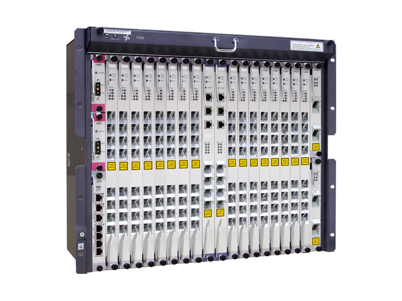
OLT: The optical line terminal is the main element of the network and it is usually placed in the Local Exchange and it’s the engine that drives FTTH system. OLT has two float directions: one is upstream getting distributing different type of data and voice traffic from users, the other is downstream getting data, voice and video traffic from metro network or from a long-haul networkand sending it to all ONT modules on the optical distribution network (ODN). The picture on the left shows an OLT.

ONT
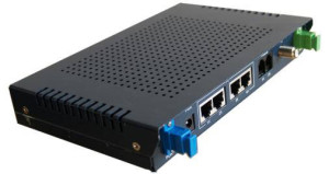
ONU/ONT: Optical network terminals or units are deployed at customer’s premises. ONTs are connected to the OLT by means of optical fiber and no active elements are present in the link. A single ONT can serve as point of access for one or multiple customers and be deployed either at customer’s premises or on the street in a cabinet. The ONU usually communicates with an ONT, which may be a separate box that connects the PON to TV sets, telephones, computers, or a wireless router. The ONU or ONT can be the same device. The picture on the right shows an ONT.

PON Splitter: Passive optical splitters divide a single optical signal into multiple equal but lower-power signals, and distribute the signals to users. The final splitting ratio can be achieved using a single splitter device.

PON Transceiver: PON transceiver is generally a bi-directional device that uses different wavelengths to transmit and receive signals between the OLT at the CO and the ONUs at the end users’ premises over a single fiber. PON transceiver can be divided into OLT transceiver module and ONU transceiver module. OLT transceiver is typically more complex than ONU transceiver.

PON splitter & transceiver

PONs offer low cost connectivity for a large number of users with high security and relatively low management needs. Telecommunications companies use PONs to provide triple-play services including TV, VoIP phone, and Internet service to subscribers. A PON could also serve as a trunk between a larger system, such as a CATV system, and a neighborhood, building, or home Ethernet network on coaxial cable. As PONs grows into millions of homes, it can be seen that a new era of access networks is upon us. Fiberstore offers a series of high reliability and affordable fiber optical access devices for PONs, including OLT, ONU/ONT, PON splitters and transceivers, to meet customers’ fast growing demand of PON deployment.

Introduction to Mode Conditioning Patch Cable

Mode conditioning patch cord (MCP) was developed as a solution for network applications where Gigabit Ethernet hubs with laser based transmitters are deployed. It is a special fiber optic patch cord and allows customer upgrading their hardware technology without the cost of upgrading fiber plant. In addition, MCP significantly improves data signal quality while increasing the transmission distance. The text will give some detailed information about mode conditioning patch cable.

What Is Mode Conditioning Patch Cable?

A mode conditioning patch cord is a duplex multi-mode patch cord that has a small length of single mode fiber at the start of the transmission leg, and also a single mode to multi-mode offset fiber connection part in this leg. There are two multi-mode fibers on one end and one multi-mode and one single mode fiber on the other end. It is fully compliant with IEEE 802.3z application standards. Mode conditioning patch cord causes the single mode transceiver to create a launch similar to a typical multi-mode launch. It is designed for long wavelength Gigabit Ethernet applications. The following picture shows the construction of a mode conditioning patch cable.

mode conditioning patch cord

How Does Mode Conditioning Patch Cable Work?

The basic principle behind the cord is that you launch your laser into the small section of single mode fiber. The launch of the light coming out of the equipment begins on a single mode fiber. The other end of the single mode fiber is coupled to multi-mode section of the cable with the core offset from the center of the multi-mode fiber. The light is launched on to the multi-mode fiber at a precise angle, giving the cable its mode conditioning properties. When we use such mode conditioning fiber optic patch cords, we need to connect the yellow leg which is the color of single mode to connect the transmit side of the equipment (single mode Gigabit transceiver) while we connect the orange leg which is the color of multi-mode to the receive side. The picture below shows how the single mode fiber is coupled to multi-mode section of the cable.

Mode Conditioning Fiber Patch Cable

How to Install Mode Conditioning Patch Cable?

To install a mode conditioning patch cable, you need to follow these steps:

  • Step1: Connect the yellow leg (single mode connector) of the MCP cable into the transmit bore of the transceiver.
  • Step2: Connect the rest orange legs (multi-mode connectors) of the MCP cable into the receive bore of the transceiver.
  • Step3: At the other end of the patch cord, put all the orange legs (multi-mode connectors) into the patch panel.
  • Step4: Repeat the above three steps for the second transceiver located at the other end of the network link.

After you have finished all the connection steps above, all the swap of transmit and receiver can only be done at the cable plant side.

Why Do We Need Mode Conditioning Patch Cable?

Transceiver modules used in Gigabit Ethernet (1000 Base-LX) launch only single mode (1300nm) long wave signals, which poses a problem if an existing fiber network utilizes multi-mode cable. When a single mode signal is launched into a multi-mode fiber a phenomenon known as differential mode delay (DMD) can create multiple signals within the multi-mode fiber. This effect can confuse the receiver and produce errors. By allowing the single mode laser launch to be offset away from the center of the multi-mode fiber, mode conditioning patch cord reduces the effect of such differential mode delay and provides a much higher operational bandwidth by precisely aligning a single mode termination at the laser transmitter. This is essential for networks using 62.5/125 and 50/125 multi-mode optical fiber and may be specified for current multi-mode networks depending upon the system requirements.

Mode conditioning patch cables are with various options, from all types of connectors to different jackets and different lengths. A variety of fiber optic connectors are available for your convenience, including: LC/UPC, SC/UPC, FC/UPC, ST/UPC, LC/APC, SC/APC, FC/APC, and MTRJ. Mode conditioning patch cables are built in the form of a simple duplex patch cable, so they can easily be installed in a system without the need for additional components or hardware. Their length can range from one meter and up to support virtually any network topography.

MPO/MTP Connector – Multi-fiber Connector for High Port Density

In today’s transmission networks, small and multi-fiber connectors are replacing larger, older styles connectors for space saving. For example, the SC connector is gradually being replaced by its small version LC connector which allows more fiber ports per unit of rack space. To save space, multi-fiber connector is also a good solution, like MTP/MPO connectors. MTP/MPO connector allows more fiber ports per unit of rack space and also satisfies parallel optical interconnections’ needs for multi-fiber connection. This article is to introduce MPO/MTP connectors in details.

MPO Connector & MTP Connector

MT ferrule

MPO is short for the industry acronym—”multi-fiber push on”. The MPO connector is a multi-fiber connector which is most commonly defined by two documents: IEC-61754-7 (the commonly sited standard for MPO connectors internationally) and EIA/TIA-604-5 (also known as FOCIS 5, is the most common standard sited for in the US). MPO connectors are based on MT ferrule (showed in the picture on the right) which can provide quick and reliable high performance interconnections up to 4, 12, 24 or more and are usually used with ribbon fiber cables. The following picture shows diagram of MPO connectors, 12-fold (left) and 24-fold (right). The fibers for sending and receiving are colorcoded, red and green, respectively.

mpo-mtp-connector-fiber-count

MTP stands for “Multi-fiber Termination Push-on” connector and it is designed by USConec and built around the MT ferrule. MTP connector is a high performance MPO connector designated for better mechanical and optical performance and is in complete compliance with all MPO connector standards. Some main improvements of MTP connector are as following:

  • The MTP connector housing is removable;
  • The MTP connector offers ferrule float to improve mechanical performance;
  • The MTP connector uses tightly held tolerance stainless steel guide pin tips with an elliptical shape;
  • The MTP connector has a metal pin clamp with features for centering the push spring;
  • The MTP connector spring design maximizes ribbon clearance for twelve fiber and multifiber ribbon applications to prevent fiber damage;
  • The MTP connector is offered with four standard variations of strain relief boots to meet a wide array of applications.
Application of MPO/MTP Connector

As mentioned, MPO/MPT connectors are compatible ribbon fiber connectors. MPO/MTP connectors cannot be field terminated, thus MTP/MPO connector is usually assembled with fiber optic cable. MTP/MPO fiber optic cable is one of the most popular MTP/MPO fiber optic cable assemblies, which are now being widely used in data center to provide quick and reliable operation during signal transmission. MPO/MTP connectors can be found in the following applications:

  • Gigabit Ethernet
  • CATV and Multimedia
  • Active Device Interface
  • Premise installations
  • Optical Switch interframe connections
  • Interconnection for O/E modules
  • Telecommunication Networks
  • Industrial & Medical, etc.
MPO/MTP Connector Selection Guide

The structure of MPO/MTP connector is a little complicated. The picture below shows the components of a MPO connector.

MPO connector components

With the drive of market requests. Various types of MPO/MTP connectors are being provided. Some basic aspects should be considered during the selection of a MPO/MTP connector are as following:

mtp-mpo-connector-male-female

First is pin option. MPO/MTP connectors have male and female design (as showed in the picture on the left). Male connectors have two guide pins and female connectors do not. Alignment between mating ferrules of MPO/MTP connectors is accomplished using two precision guide pins that are pre-installed into the designated male connector. Second is fiber count: MPO/MTP connector could provide 4, 6, 8, 12, 24, 36, 64 or more interconnections, among which 12 and 24 are the most popular MPO/MTP connectors. In addition, like other fiber optic connectors, the selection of a MPO/MTP connectors should also consider fiber type and simplex or duplex design.

MPO/MTP Connector is a popular multi-fiber connector for high port density. It can offer ideal solution to set up high-performance data networks with the advantages of time saving and cost saving. As an important technology during migration to 40/100 Gigabit Ethernet, MTP/MPO connector is now being adopted by more and more data centers.

LC Connector Introduction

Fiber optic connectors are used to the mechanical and optical means for cross connecting fibers. Fiber optic connectors can also be used to join fiber cables to transmitters or receivers. There have been many types of connectors developed for fiber cable. Single mode networks have used FC or SC connectors in about the same proportion as ST and SC in multimode installations. But LC connector with smaller size and higher performance has become popular and the connector choice for optical transceivers for systems operating at gigabit speeds. The following text gives a detailed introduction of LC connector.

History of LC Connector

LC stands for Lucent Connector, as the LC connector was developed by Lucent Technologies as a response to the need by their primary customers, the telcos, for a small, low insertion loss connector. Then the LC design was standardized in EIA/TIA-604-10 and is offered by other manufacturers.

SC connector and LC connector

Advantages of LC Connector

There are solid reasons that the LC is the preferred connector for high-performance network. From the appearance, LC connect is like a mini size of SC connector. LC connector borrows split-sleeve construction and a cylindrical ferrule (usually ceramic) from SC connector. LC connector has a push-and-latch design providing pull-proof stability in system rack mounts. The picture on the right shows the appearance of SC connector and LC connector.

The ferrule size of LC connector is 1.25 mm which is half the size of SC connector ferrule—2.5 mm. LC connector is rated for 500 mating cycles and its typical insertion loss is 0.25 dB. An interesting feature of the LC is that, in some designs, the ferrule can be “tuned” or rotated with a special tool after it has been assembled. This offers a considerable performance advantage. The design and performance of LC connector address the need for high density and low insertion loss.

Application of LC Connector

LC connector can be found in many places for termination and connection, especially SFP transceivers for gigabit transmission. For example, the optic interfaces of Cisco SFP transceivers are all LC connectors. Some other applications are as following:

Simplex and duplex LC connectors

  • Telecommunication networks
  • Local area networks
  • Data processing networks
  • Cable television
  • Fiber-to-the-home
  • Premises distribution
LC Connector Selection Guide

To meet the needs of market, there are various types of LC connectors provided now. During the selection of LC connector, transmission media should be the first factor to consider. LC connector favors single mode fiber optic cable. But it can also be used with multimode fiber optic cable. Signals sometimes are transferred over simplex fiber optic cable and sometime duplex fiber optic cable. Thus, LC connector has both simplex and duplex design. The picture above shows an APC simplex LC connector on the left and a UPC duplex LC connector on the right. Some other factors like polishing style (APC or UPC), hole size and cable diameter should not be ignored. For more details about LC connectors, you can visit Fiberstore which provides various LC connectors with high performance and low price.

Introduction of PC, UPC and APC Connector

When we choosing a LC connectors, you might hear descriptions like LC UPC polished fiber optic connector, or LC APC fiber optic connector. Or when you are choosing a ST fiber optic patch cable, you can find the description like ST/PC multimode fiber optic patch cable. What do PC, UPC, APC stand for? The following text will give the explanations.

fiber optic connector ferrule

PC (physical contact), UPC (ultra physical contact) and APC (angle physical contact) are the polish style of ferrules inside the fiber optic connectors. Unlike copper cables with copper wire in the connectors as connection media, fiber optic connectors are with ceramic ferrules for connection. The picture on the left shows the ferrule in fiber optic connector. Different fiber optic connectors has different ferrule size and length. Also their polish style might be different.

To better understand the why we have PC, UPC and APC, let’s start with the original fiber optic connector which has a flat-surface and is also known as flat connector (showed in the following picture). When two flat fiber connectors are mated, an air gap naturally forms between the two surfaces from small imperfections in the flat surfaces. The back reflection in flat connectors is about -14 dB or roughly 4%. To solve this problem, the PC connectors came into being.

flat fiber connector

In the PC connector, the two fibers meet, as they do with the flat connector, but the end faces are polished to be slightly curved or spherical. This eliminates the air gap and forces the fibers into contact. The back reflection is about -40 dB. The following picture shows two end faces of PC connectors.

PC connector

UPC connector, usually has a blue-colored body, is an improvement to the PC connector with a better surface finish (as showed in the following picture) by an extended polishing. The back reflection of UPC connector is about -55 dB which lower than that of a standard PC connector. UPC connectors are often used in digital, CATV and telephony systems.UPC connector

PC and UPC connectors have reliable, low insertion losses. However, their back reflection depends on the surface finish of the fiber. The better the fiber gain structure, the lower the back reflection. If the PC and UPC connectors are continually mated and remated, back reflection will degrade. An APC connector won’t have such problem. Its back reflection does not degrade with repeated matings.

APC connector

APC connector usually has a green body with an end-face still curved but are angled at an industry-standard 8 degrees (showed in the above picture) which allows for even tight connections and smaller end-face radii. Thus any light that is redirected back towards the source is actually reflected out into the fiber cladding, again by virtue of the 8 degree angled end-face. APC ferrules offer return losses of -65dB. Some applications that are more sensitive to return loss than others that call for APC connectors, like FTTx and Radio Frequency (RF) applications. APC connectors are also commonly used in passive optical applications due to the fact that many of these systems also use RF signals to deliver video.

APC connector and UPC connector

PC, UPC or APC, which should be the choice of fiber optic connector? The answer is it depends. Choosing the appropriate connector for a fiber network depends on things such as, network design and function. Fiberstore offers a wide range of fiber optic connector as well as professional optical network solution. For more information you can visit Fiberstore.

Why Choose Direct Attach Cable in 40G/100G Migration?

Advance technologies like Big Data and Cloud which require high speed of data rate become more and more popular. To meet the ever growing need to high speed data transmission, many data centers are migrating from 10 GbE to 40 GbE or even 100 GbE. And some are considering about the migration, during which the cost is one of the most important factors to consider. Direct attach cable also known as DAC cable is a cost effective solution during the migration to 40GbE or 100GbE.

What Is Direct Attach Cable

A direct attach cable also known as DAC is usually a fixed assembly supporting high speed data that uses a small form-factor connector module as an optical transceiver on each end of a length of cable. With significant cost-saving and power-saving benefits, direct attach cable is now being widely used in data centers for short reach applications. It can be connected to switches, servers, routers, network work interface cards (NICs), Host Bus adapters (HBAs) providing high density and high data throughput.

Why Choose Direct Attach Cable

Direct attach cable with many significant benefits can satisfy the growing need for high speed data. The main benefits of direct attached cable are described in the following text.

Cost saving: the modules on the end of direct attach cable looks like optical transceivers. However, actually they very much different from optical transceiver. These small form-factor connector modules leave out the expensive optical lasers and some electronic components. That’s the main reason why the DAC is much cheaper than optical transceiver. Direct attach cable in some case can be an alternative to optical transceivers as it eliminates the separable interface between transceiver module and optical cable. Thus, choosing DAC in some cases can save a lot of money as well as time.

Low power consumption: to identify the modules on the end and cable type to the Ethernet interface, in both active direct attach cable and passive direct attach cable a small electrical component is used, which is low cost and consumes very little power compared with optical transceiver.

Supporting high data rate: DAC can provide high speed I/O (input and output) data. The most commonly used DAC can support high data rate of 10 Gb/s and 40 Gb/s. However, as technologies advanced, some vendor can provide direct attached cable supporting 120 Gb/s, like 120G CXP Cables.

Meet small form-factor standards: the modules on each end of DAC meet small form-factor standards which means DAC inherits some advantages of the small form-factor module, like space saving. Some time there is no need to upgrade the equipment by using a DAC.

40GBASE QSFP+ Direct Attach Cable

With various benefits like abilities in data transmission and cost saving, direct attach cable is becoming increasingly popular for short distance top-of-rack (ToR) and middle-of row (MoR) data center deployments. It’s a cost-effective solution to 40G/100G migration. Currently direct attach cable are continuing to evolve to meet industry needs. Various types of directive attach cable are being provided. FS.COM as a vendor of optical components provides DAC cable assemblies including 10G SFP+ Cables, 40G QSFP+ Cables, and 120G CXP Cables.

Related Article: Use High Speed Direct Attach Cable for Data Center Interconnection

How to Select the Right Fiber Patch Cable

A fiber patch cable, also known as fiber patch cord, which is widely applied to connect telecommunication equipment and backbone cabling, is a length of fiber optic cable capped at either end with connectors that allow it to be rapidly and conveniently connected to CATV, an optical switch or other telecommunication equipment.

As the fiber patch cables are used to cross-connect installed cables and connect communications equipment. The choice of fiber patch cable is very important to the performance of the network. Currently vendors offer fiber optic patch cables in a variety of cable and connector types. In order to select the right patch cable, some attributes needed to be obtained. They are fiber type, connector type on each end, simplex or duplex, jacket type and length. Fiberstore offers you the following tips to choose the proper fiber patch cable for your applications.

Choose the right fiber type—fiber patch cable should use the same fiber type as the fiber optic cabling that it is connected to. Fiber optic cable comes in two general types which are single-mode and multi-mode fiber.

LC-ST Duplex Multimode Fiber Patch Cable

Choose the correct connector type—the connectors on both end of fiber patch cable are used to connect to the patch panels and equipment. Connector types of the patch cable must match the patch panels and equipment. They can be the same and can also be different. For example, a fiber patch cable with a ST connector on each end is known as ST to ST patch cable. A fiber patch cable with a LC connector on one end and a ST connector on the other end is known as LC to ST patch cable.

Simplex or duplex—unlike copper patch cable which sends information in both directions, most fiber patch cord cables have a single strand of fiber allowing for signal flow in one direction only. A simplex patch cord is a single-fiber cable with simplex connection terminations. A duplex patch cord is a two-fiber cable with duplex connectors. Connecting equipment so that it can send and receive information requires two strands of fiber (one to transmit and one to receive information). This can be accommodated by using two “Simplex” (single strand of fiber) cables for each equipment interconnection or a “Duplex” cable, with conductors and/or connectors bonded together in pairs.

ST-ST-Fiber-Patch-Cable

Jacket of fiber patch cable—flammability of the jacket material could become an issue if the area they are in has special requirements for flame spread or products of combustion in case of a fire. To answer the market call, there are LSZH (low smoke zero halogen) fiber patch cable whose jacket is made of materials free of halogenated materials like fluorine (F), Chlorine (Cl), Bromine (Br), Iodine (I) and Astatine (At). This type of fiber patch cord won’t release low smoke zero halogen when it’s on fire.

Length—overall length of the patch cable may be specified in feet or meters, depending on your preference.

Fiberstore provides various types of fiber optic patch cables including single-mode, multi-mode, multi-core, armored patch cables, as well as fiber optic pigtails and other special patch cables. For most of the patch cables, the SC, ST, FC, LC, MU, MTRJ, E2000 connectors (APC/UPC polish) are all available. In addition, we also have MTP/MPO cables in stock.

Some Common Fiber Optical Transceiver

Fiber optic transceiver including both transmitter and receiver in a single module is an important equipment transmitting and receiving data to support the normal operation of optical fiber data transmission system. The market currently offers a wide selection of fiber optic transceiver for use with different types of wire, fiber and wavelength and so on.

A group of companies joined together to agree on package standards also called multisource agreements (MSAs). The package standards help customers choose the best transceivers to their applications and make sure the they can use transceiver from multiple vendor without redesigning the board. In the following text, some common fiber optic transceivers according to package standards are introduced in details.

9-PIN&GBIC&SFF
9-Pin transceiver
 is also known as 1×9 optical transceiver. This transceiver has a single row of output pins at the rear of the device. The optical interface is usually ST or duplex SC receptacles. It is mainly used in fiber optic transceiver, optical switches, single/multi-mode converter as well as some industrial control applications.

GBIC transceiver, namely gigabit interface converter transceiver, is a plug-in interface designed to allow a pluggable interface for Gigabit Ethernet. It offers a standard, hot swappable electrical interface and can support a wide range of physical media from copper to long-wave single mode optical fiber, at lengths of hundreds of kilometers. However, this type of transceiver is gradually replaced by SFP transceiver which has more advantages.

SFF (small form-factor) transceiver is a compact optical transceiver used in optical communications for both telecommunication and data communications applications. Compare to 9-pin and GBIC transceivers, SFF transceivers is smaller allowing more ports in a given area. SFF transceivers have 10 or 20 I/O (input/output) pins that solder to the board.

SFP&SFP+&XFPSFP transceiver, small form-factor pluggable, small hot-pluggable optical module is a pluggable version of SFF transceiver and an upgraded version of the early GBIC module, with 10 I/O connections at the rear of the package. With smaller volume and higher integration, it is currently the most popular fiber optic transceiver.

SFP+ transceiver, also called enhanced SFP or SFP plus, with a higher transmission rate usually up to 8.5 G or 10 G, is a kind of optical transceiver module specified for 8Gbps/10Gbps/16Gbps fiber channel and 10Gigabit Ethernet applications.

XFP transceiver, 10Gigabit small form-factor pluggable transceiver, is the next generation SFP transceiver for 10Gbps application. This type of transceiver is hot-swappable and protocol-independent and is usually used to 10Gbps SONET/SDH, fiber channel, Gigabit Ethernet and other applications, but also of CWDM DWDM link.

X2&XENPAK
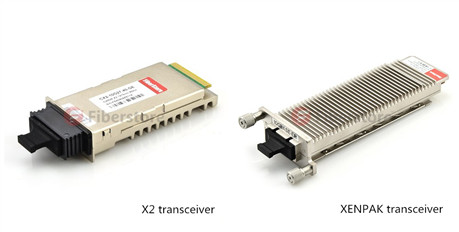
XENPAK transceiver is a pluggable transceiver for 10Gbps applications, specifically 10 Gigabit Ethernet. The electrical interface is called XAUI, which provides four 2.5Gbps signals to the transmitter, which multiplexes or serialize them into a single 10Gbps signal to drive the source. It uses a 70-pin electrical connector. The optical interface is usually a duplex SC.

X2 transceiver is based on the XENPAK transceiver standards. It is shorter than XENPAK transceiver but uses same 70-position electrical and duplex SC interfaces. Unlike XENPAK, X2 devices mount on top of the board and are low enough to allow boards to be stacked side by side.

Introduction of Fiber Optic Sensor

Optical fibers are mainly applied in telecommunications, which has significantly changed this industry. However, there is also a growing application of optical fibers in sensing applications for measurement. Many components associated with optical fibers are developed to sensing applications. One of the most significant components—fiber optic sensor (also known as optical fiber sensor) is now being widely used in sensing applications.

Fiber optic sensors are fiber-based devices to sense some quantities like temperature, pressure, vibrations, displacement, rotations or concentration of chemical species. The basic instrumentation required for sensor are optical source (often a single-frequency fiber laser), sensing element, optical detector and end-prossesing devices (optical-spectrum analyzer, oscilloscope). A block diagram of fiber optic sensor is showed in the following picture.

8-30-2014-10-06-53-AM

Fiber optic sensor offers a wide range of advantages, which makes it being applied in many field successfully. Its advantages are as following.

  • Explosion proof: In fiber optic sensor, the primary signal is an optical. Therefore, there is no risk of spark or fiber.
  • Immunity to electromagnetic interference: Since the fibers are composed of dielectric such as glass. The fiber optic sensor is immune to radio frequency and electromagnetic.
  • Small size, light weight and flexible: This feature extends the applications of fiber optic sensor to many fields, like aircraft.
  • High sensitivity: The optical fiber sensors are highly sensitive and have large bandwidth. When multiplexed into arrays of sensors the large bandwidths of optical fibers themselves offer distinct advantages in their ability to transport the resultant data.
  • Remote sensing: With the availability of low loss optical fibers, the optical signal can be transmitted up to a long distance transmitted up to a long distance (10-1000m). Thus the remote sensing is possible with the optical fiber.
  • Environmental ruggedness and resistant: The optical fiber are manufactured from non-rusting materials such as plastics or glasses, therefore, the fibers have excellent stability when in permanent contact with electrolyte solutions, ionizing radiation etc. Further the fibers can withstand high temperature as high as 350 ca. Special fibers can extend sensor operation beyond 350c to as high as 1200c.
  • Compactness: With the availability of solid-state configurations (small size sources and detectors) it is possible to design a compact optical fiber sensor system.

Based on the sensor location, the fiber optic sensors are generally classified into two types, namely intrinsic and extrinsic fiber optic sensor.

Intrinsic fiber optic sensor can provide distributed sensing over very large distances, which is the most useful feature of it. In intrinsic fiber optic sensor, sensing takes place within the fiber itself. Only a simple source and detector are required. This sensor depends on the properties of the optical fiber itself to convert an environmental action into a modulation of the light beam passing through it. The basic concept of the intrinsic fiber optic sensor is showed in the picture below.

Intrinsic fiber optic sensor

Extrinsic fiber optic sensors use an optical fiber cable, normally a multimode one, to transmit modulated light from either a non-fiber optical sensor, or an electronic sensor connected to an optical transmitter. In this sensor, the fiber may be used as information carriers that show the way to a black box. It generates a light signal depending on the information arrived at the black box. The black box may be made of mirrors, gas or any other mechanisms that generates an optical signal. These sensors are used to measure rotation, vibration velocity, displacement, twisting, torque and acceleration. The major benefit of these sensors is their ability to reach places which are otherwise unreachable. The best example of this sensor is the inside temperature measurement of the aircraft jet engine. The following picture shows the basic concept of the extrinsic fiber optic sensor.

Extrinsic fiber optic sensors

Fiberstore offers fiber optic sensors of high quality. For more information about fiber optic sensor, you can visit its online shop.

FTTH Makes Your Life Better

The way people live, work and play has been changed by the high speed bandwidth carried by fiber optic cables. People communicate via social networks like Facebook or Twitter, share videos online, watch Internet movies on television, take advantages of telemedicine and home based businesses. Without fiber optic cable, none of these activities can be carried out smoothly.

FTTH

To further improve the speed of bandwidth for users, FTTH (fiber to the home) are being widely accepted in cabling. Fiber to the home (FTTH) is the delivery of a communications signal over optical fiber from the operator’s switching equipment all the way to a home or business, thereby replacing existing copper infrastructure such as telephone wires and coaxial cable. By using the FTTH technologies, fiber reaches the boundary of the living space, such as a box on the outside wall of a home.

A key benefit of FTTH is that it provides much faster Internet speeds than twisted pair conductors, DSL or coaxial cable. However, what FTTH can bring for people is not just the faster speed. The real value of FTTH is that it can meet the exploding demand for more services. Therefore, people can do entirely new things and enjoy more new products and services with the networks.

FTTH is widely accepted now and making people’s life much more convenience and better. It also becomes an element like good water, power, transportation to define successful communities. FTTH-powered bandwidth is essential for people who work at home and who want quality life provided by online entertainment, education, culture and e-commerce.

2 Fibers Single-mode FRP Strength member Messenger Wire LSZH FTTH Drop Cable-GJXFH

Fiberstore’s FTTH Optic Fiber Cable Solution

Demand for bandwidth is rising with the introducing of new products and services. As a part of infrastructure, demand for FTTH fiber optic cable is also rising. FTTH Fiber Optic Cable is a kind of special curved optical fiber, which providing greater bandwidth and enhanced network transmission characteristics. This cable replaces the standard copper wire of the local Telco as it can carry high-speed broadband services integrating voice, data and video, and runs directly to the junction box at the home or building.

Fiberstore supplies various FTTH optic fiber cables, like FTTH Indoor Cable, FTTH Drop Cable, FTTH Duct Armored Cable, etc. In order to cut inventory costs and speed up the installation process for our customers, Fiberstore’s FTTH cable designs can simplify your project. For more information please visit Fiberstore’s Online shop (fs.com).

How to Choose the Fittest Network Face Plates?

Although FTTx is now being widely applied, many places are not able to use optical fiber or FTTx. For example, CAT6 or CAT5e cables are still occupying a certain proportion comparing with fiber optic cables. In some places FTTx and CAT5e/CAT6 network cables are being operated at the same time. In the mentioned situations, network face plates should be taken into consideration during cabling.

Network Face Plate is usually a plastic plate with one or more ports, which allows copper network cables to run between rooms beneath floors and behind walls. It is important to choose appropriate network face plates or wall plates during cabling.

Before you install network face plates, you should know which ones satisfy your needs most. The face plates you choose should conform to the standard you have chosen for your overall system. A good choice of network face plates or wall plates will not only help to maintain the quality of your infrastructure, but also save valuable spaces and cost. How to select the appropriate network face plates and wall plates? The following will give you the answer.

First, you should make sure how many types of cables you need to run. Usually, people need multiple medium to maintain communication. For example, telephone, Internet and TV are always the “must-have” medium during home network cabling. They should be connected with different network face plates. You might need several network face plates separately with RJ45 port, RJ11 port and TV port. However, in many situations, those cables come into home from one location. Then, it could be really bothering to install these face plates one by one. In addition, it’s not space saving and the appearance is not nice. Luckily, you can find that many manufacturers are providing network face plates with multiple ports in one to meet your specific networking needs. For example, except the network face plate with one port, Fiberstore also provides many other network face plates like the followings:

  • Face plate with one or more RJ45 port(s) and one or more TV port(s)
  • Face plate with a RJ45 port, RJ11 port and a TV port
  • Face plate with a RJ45 port, a RJ11 port, as well as an electrical socket and switch.

wall face plate with two RJ45 ports and two TV portsone RJ45 port, one RJ11 port, one electrical socket and one switch in a wall face plate

The above picture on the left shows a network face plate with two RJ45 ports and two TV ports. The above picture on the right shows a network face plate with one RJ45 port, one RJ11 port, one electrical socket and one switch.

Fiberstore could even provide RJ45 wall plate with a RJ45 port and a SC port for the situations in which both copper cable and fiber optic cable are being used.

RJ45-SC wall plate

The above picture shows a RJ45 wall jack with a RJ45 port and a SC port.

The size of the network face plate is another thing should be considered during cabling. There are generally 3 types of standard network face plates. They are known as 86 type, 118 type and 120 type network face plates. 86 type network face plate is square, with a size of 86*86mm, with one to three ports. 118 type network face plate is a rectangle network face plate generally with a 118*72mm size or other sizes. 120 type network face plate usually has a size of 120*120mm, 120*60mm or other accordingly.

One more thing cannot be ignored during network cabling is the cable type. The most commonly used copper network cables are CAT5e or CAT6. It is essential to make sure whether the network face plates are suitable for the cables you chose.

By taking the mentioned aspects into consideration, you are sure to find the right network face plates for your needs.

Fiberstore supplies a variety of network face plates, such as AMP Face Plate BS Shuttered, 86 type network face plates, 118 type network face plates. These face plates are available with 1 port, 2 ports, 4 ports, etc. Our high quality network face plates are compliant with international standards with low price and worldwide delivery. They can help you save time & money for your business or project.

Plastic Optical Fiber – A “Consumer” Optical Fiber

If you are thinking of pre-wiring or rewiring your home network, there are many alternatives to consider. POF (Plastic optical fiber) could be one of your options. It is usually called as “consumer” optic fiber, as it is a low-cost optical fiber alternative with flexibility and ease of end finish.

plastic optic fiber

Plastic optic fiber is a large core step-index fiber with a typical diameter of 1 mm, which typically uses PMMA (acrylic), a general-purpose resin as the core material, and fluorinated polymers for the cladding material. It is a specialty fiber has various advantages and is useful for illumination, sensors and low speed short data links and so on.

Plastic optical fiber works in the same manner as glass optical fiber but uses plastic instead of glass. Although POF has a higher attenuation than glass optical fiber, it is acceptable for certain applications. Because it has merits that the glass optical fiber does not have. Unlike glass, plastic optical fiber has a larger core made out of PMMA and larger numerical aperture, which is capable of withstanding tighter bend radius than glass optical fiber. Thus it can be easily be cut and bent to fit in hard-to-reach places. Besides, the cost of plastic optical fiber is much lower.

POF has a data transfer speed lower than glass optical fiber, but comparing with the more traditional copper wiring, POF has a much faster transfer speed. Plastic optical fiber also has the merits that copper wiring does not have. They are as following:

  • POF is Complete immunity to electromagnetic interference (EIM).
  • POF is an electrical insulator, which can be laid down in power ducts.
  • POF has lower weight than copper wiring.
  • POF is cheaper than copper wiring

With the growing demand for high-speed communications over private intranets and the internet, varied applications with plastic optical fiber have been developed and commercialized. Plastic optical fibers can be used as light transmission guide in displays or as sensors and telecommunications cables. The uses of POF can be found in but not limited to the following fields: FTTH, automotive, medical, intelligence, lighting, sensor, digital audio and video interfaces.

If you are looking for plastic optical fiber for cabling, Fiberstore will satisfy your needs. It provides both simplex plastic optical fiber and duplex plastic optical fiber. For more information about Fiberstore’s POF products, you can visit its online store by clicking the following words: plastic optical fiber.

Introduction of Fiber Optic Wall Plate

When talking about fiber optic cabling system, the related products that come to our mind firstly are usually fiber optic cables, fiber optic transceivers, connectors or fiber optic transmission products. However, there are still many other components whose importance should not be ignored. Fiber optic wall plate, or outlet, is one of these components, and is also one of the most visible components in a fiber optic cabling system. This text will introduce you this component and offer you the Fiberstore‘s fiber optic wall plate solution.

What is Fiber Optic Wall Plate?

Fiber optic wall plate is a flat plastic or metal plate that allows connection to fiber cable carrying optical signals. It serves as a transition point between the fiber optic cable and equipment. Fiber optic wall plates are usually mounted in or on walls, but some of them can also be mounted in floors and ceilings. Fiber optic wall plate includes one or more ports, and each port is available with an adapter.

Applications of Fiber Optic Wall Plate

Fiber optic wall plates are designed to bring fiber to the desk and widely used in multi-floor and high building. It can be found in:

  • FTTH access
  • Telecommunication
  • CATV
  • Data Communication Networks etc.
Types of Fiber Optic Wall Plate

Fiber optic wall plates come in many different types according to their adapter type, port number and faceplate interface.

According to the faceplate interface of the plates, there are bevel fiber optic wall plates and hybrid fiber optic wall plates.

Fiber optic wall plates can contain one or more adapters. The number of ports a plate can have is based on the size of the plate. Here listed some of the fiber optic wall plates:

  • Single port fiber optic wall plates
  • 2-port fiber optic wall plates
  • 3-port fiber optic wall plates
  • 4-port fiber optic wall plates
  • 6-port fiber optic wall plates
  • 8-port fiber optic wall plates
  • 12-port fiber optic wall plates

The following picture shows a single port ST fiber optic wall plate outlet.

wall plate

To satisfy different demands during cabling, sundry kinds of adapters could be installed on fiber optic wall plates. And these adapters could be the same ones or different. If classified by the adapters, the types of fiber optic wall plates will be various. Parts of the fiber optic wall plates classified by the adapters are listed as following:

  • FC fiber optic wall plates outlets
  • SC fiber optic wall plates outlets
  • ST fiber optic wall plates outlets
  • LC fiber optic wall plates outlets
  • SC-ST fiber optic wall plates outlets
  • RJ45-SC fiber optic wall plates outlets
  • SC-ST-LC fiber optic wall plates outlets
  • FC-SC-ST-LC fiber optic wall plates outlets

wall plate pic 2

The above picture shows a 2-port FC bevel fiber optic wall plate outlet. The picture below shows a 4-port SC/ST/FC/LC hybrid fiber optic wall plate outlet.

wall plate pic 3

Fiberstore’s Fiber Optic Wall Plate Solution

Fiberstore supplies different types of fiber optic wall plates, including bevel fiber wall plates with 45° adapter plug-in/out angle and hybrid fiber wall plates/outlets. These wall plates are available with LC, SC, ST, FC adapters (or hybrid with RJ45 port) and up to 4 ports. All the wall plates are with high quality and secure to any surface, drywall, baseboard, and even modular furniture.