Server Rack Sizes: How to Choose a Right One?

A server rack is an equipment that holds all kinds of network devices ranging from switches, patch panel racks, to cable organizer and so on. Generally, the very first step in rack cable management is to get a container like 42U server rack to support all your devices. However, as there are so many server rack sizes on the market, how to get the one that is ideal for your application needs to be well thought of. Here we can offer some way out.

Common Server Rack Sizes

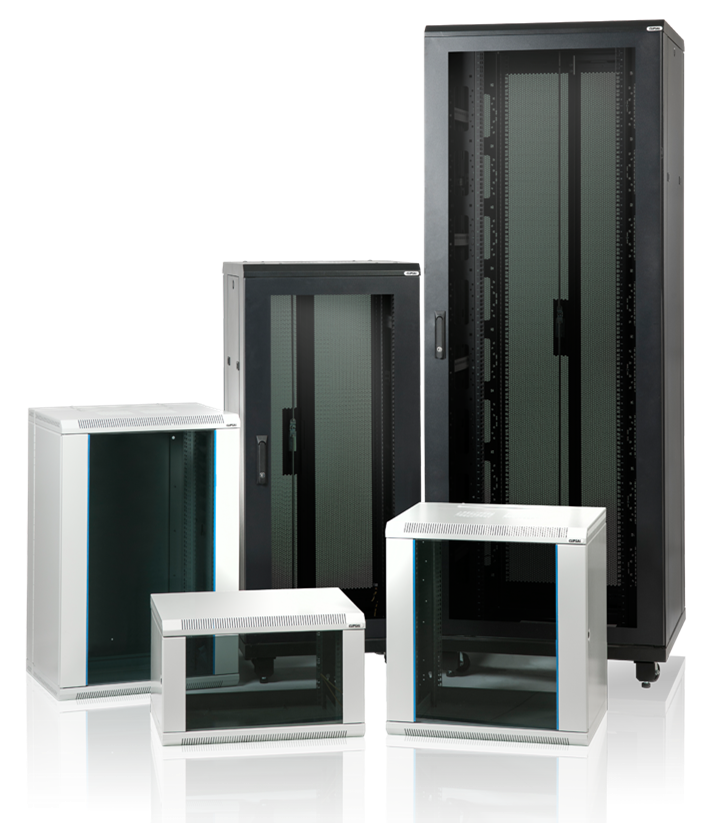
Based on different application requirements, different server rack sizes are produced. The three common types of server racks are open frame rack, rack enclosure and wall-mount rack.

Server Rack Sizes: Rack Enclosure

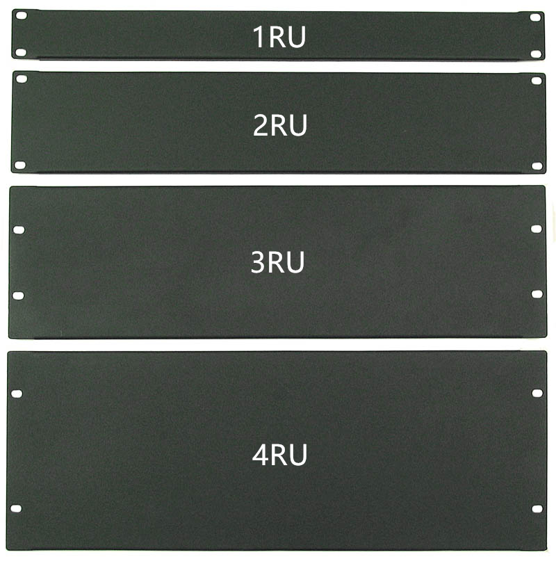
The rack enclosure, also known as server rack cabinet, usually comes in 40U,42U or 45U. It contains removable doors at both front and rear sides, removable side panels and adjustable vertical inside mounting rails, which provides an easy way to install and take out devices. The specially designed perforated door allows for smooth ventilation. Server rack cabinet may come in different height and depth. The height is usually represented by “U” and one U space equals to 1.75 inches. Whereas the depth refers to the distance between the front of the rack and the rear. FS.COM offers 9U server rack, 12U server rack, 42U server rack and 45U server rack. There may be server racks with 48u rack height on the market, which can accommodate as many as 24 2U devices.

server rack sizes, rack cabinet

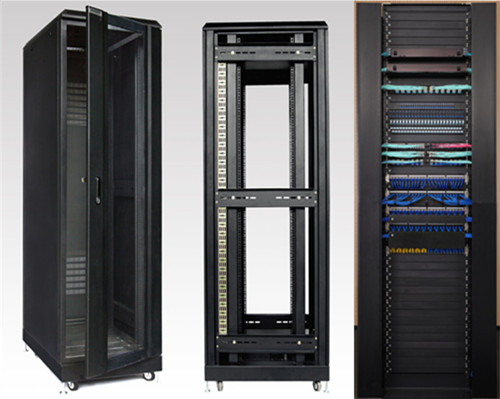
Server Rack Sizes: Open Frame Rack

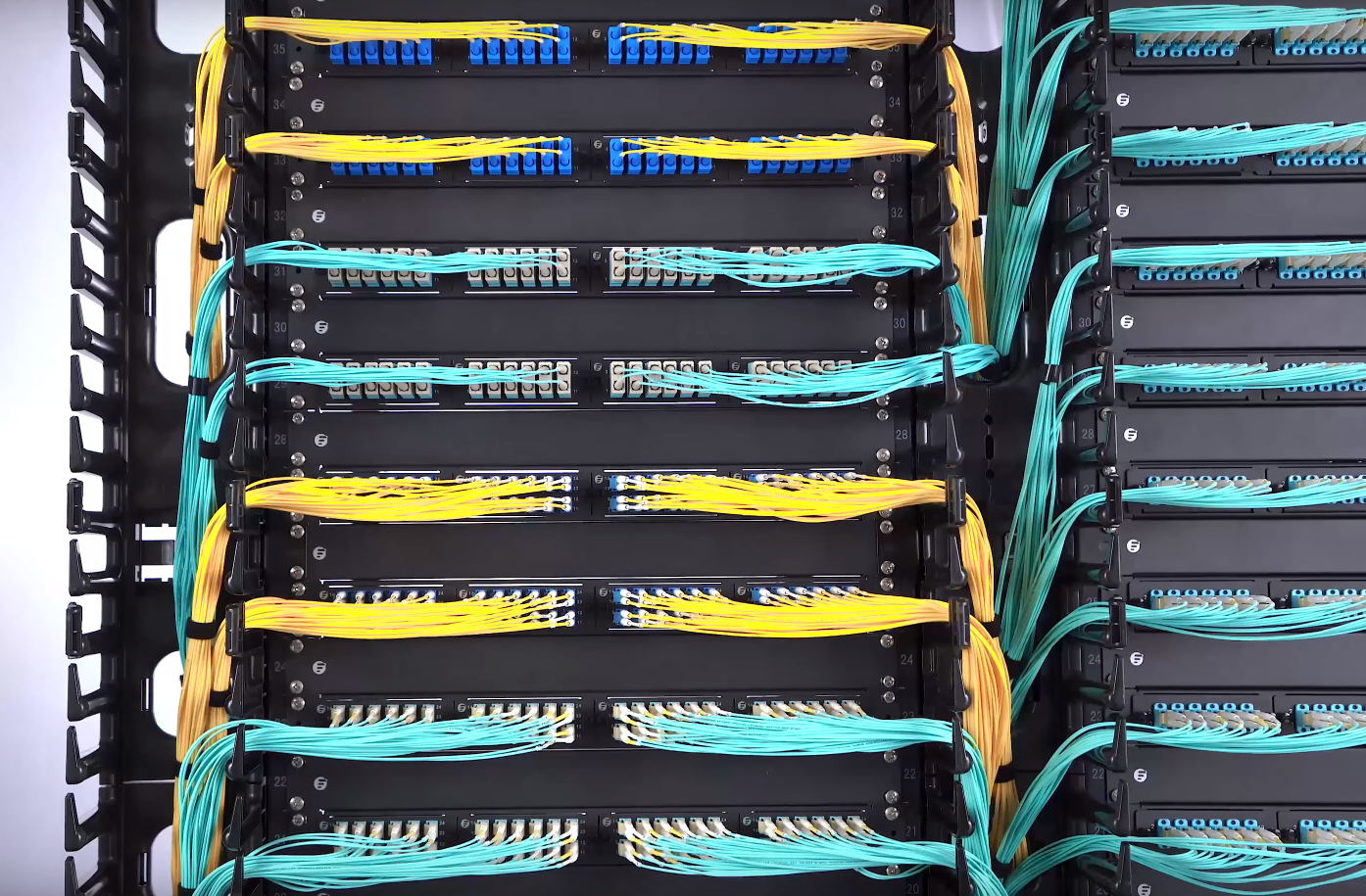
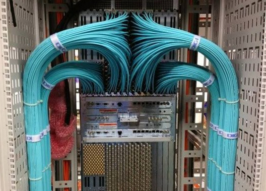
Open frame rack resembles rack enclosure in shape, but it is designed without doors or side panels. Just two or four bare rails are largely economical and leave easy access to cabling. And its common rack size is 45U. Ventilation is no longer a headache for expertise. However, it may expose all your applications to the external environment, resulting in bad appearance or even damage. Given this, open frame racks are optimal for network wiring closet and distribution frame applications that have high-density cabling.

server rack sizes, open frame rack

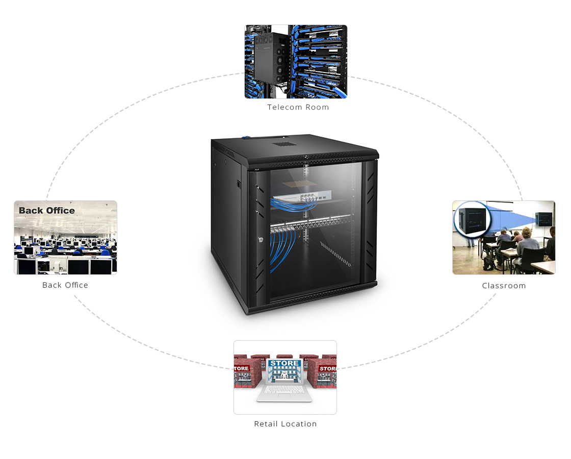
Server Rack Sizes: Wall-mount Rack

Wall-mount rack, the relatively small server rack fixed on the wall, is like a miniature rack enclosure. Usually, the wall-mount server rack sizes are 6U, 9U, 12U and 18U. As it doesn’t occupy the floor space as the former two, the wall-mount cabinet is spacing-saving which can be its selling point. It is suitable for your household use which does not include large and complicated equipment.

server rack sizes, wall-mount server rack

How to Choose from These Server Rack Sizes?

If you are not restricted by the space, you can choose from the rack enclosure and open frame server rack. Just calculate the required height and depth of your applications. For example, assume that you need to add 5 2U rack servers to your data center. A 12U server cabinet(21 inches) would be ideal, because 2 x 1.75 x 5 = 17.5 inches of space. The same is to the depth. Remember leaving some cabinet space for both the front and rear for future expansion and current rack cable management. Otherwise, a wall mount server rack is recommended as it is space-saving when you don’t have enough room for floor-standing cabinet. Check out the maximum weight it can hold.

Conclusion

Since the server rack is not flexible or scalable, we must plan carefully for the server rack sizes, and take into consideration the dimension and shape of server racks. As for the quality, rest assured that FS.COM offers sturdy cabinets with reasonable price. We are ready to provide you with the best solution.

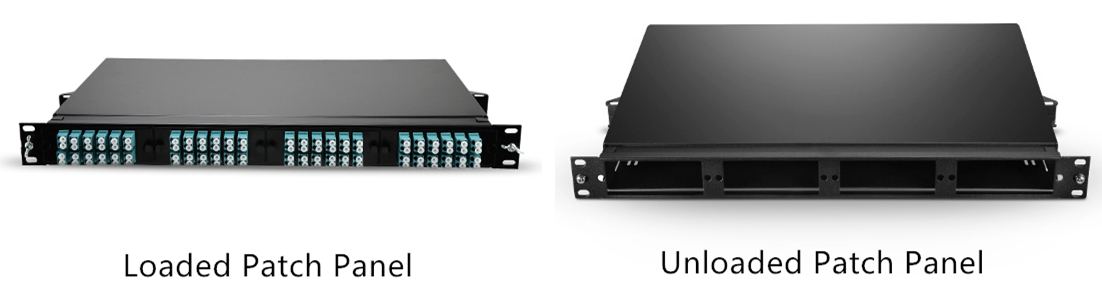
Related article: Wall Mount vs Rack Mount Patch Panel

How to Use Vertical Cable Organizers for Rack Cable Management

Cable management, especially rack cable management, is a always the time-consuming and tedious job for IT network workers. Cable organizers like patch panel, 1U/2U cable managers and D-rings are commonly used by network workers in server rack cable management. Then how to use these cable organizers for rack cable management effectively? This article will explore some details for you.

Single-sided Cable Organizer in Rack Cable Management

The single-sided vertical cable organizers, also known as cable manager, are usually installed on open frame racks to organize and protect cables. As it is single-sided, the finger ducts are facing towards the front side or users. It is in most cases attached to the rack and won’t take up much room in rack cable management. The 45U single-sided cable organizer provided by FS.COM is capable of managing all the fiber and copper cables in a server rack. It is equipped with molded cable management fingers which have integral bend radius control. Each of this single-sided vertical cable manager consists of two 22.5U sections in one package. The two parts can be seamlessly combined together when they are installed along a standard 45U height server rack. The user-friendly cover on this rack cable organizer can help protect the cable from damage and dust-proof, and also hide the cables inside.

vertical cable organizer

Dual-sided Cable Organizer in Rack Cable Management

Different from the single-sided cable organizer, the dual-sided cable manager is designed with management fingers on both front and rear sides. The double-sided structure enables the maximize space utilization, which can better meet the vertical cable management need. The 45U plastic dual-sided vertical cable organizer is deployed to deal with the slack cables, preventing the chaotic cable runs. Its soft finger ducts on front and back sides allowing for quick and easy cable routing on the server racks. Two 22.5U sections being coupled seamlessly form a complete 45U dual-sided vertical cable manager which is suitable for both fiber and copper cabling. The covers on both sides can protect cables from damage and dust. It can be a good partner of horizontal cable managers. In addition, this vertical cable manager has multiple finger ducts that can store a large number of cables.

How to Use Vertical Cable Organizers for Server Racks

The vertical cable organizers are often deployed where cables run chaotically. When applying them, assemble all the gadgets including the cover and the easily inserted brackets. Use screws to fix them on the open frame rack. After the two 22.5U dual-sided cable organizers being matched seamlessly, the cable management can go on. To produce a tidy and clean appearance, care should be given that the cables on the same row should be passed through the same gaps between two fingers. Get some cable ties to achieve better effects. After the cabling, close the cover. Success. Here is a video introducing how to apply vertical cable organizers in rack cable management.

Conclusion

Vertical cable organizer, or vertical cable manager, can simplify rack cable management effectively. It has nothing to do with the network but serves the cable management. In the cabling system, only combing the cable runs clearly can the network system work in an orderly way. FS.COM has been all along working on the growing conundrum to offer you market-leading quality and novel design. We now have different cable organizers available for your reference to deal with vertical and horizontal cable management.

Fiber Connector Type: SC APC vs SC UPC

With the rapid development of fiber networks, fiber connectors have become an essential assembly to cater for high-performance fiber optic system. There are various fiber connector types in the market, such as LC, ST, SC, MPO/MTP and so on, among which, SC is one of the most commonly used fiber connectors. Further Classifying SC by polishing type, we have SC APC connector and SC UPC connector. This article will introduce SC APC vs SC UPC and illustrate their difference for your selection guide.

SC APC vs SC UPC: What Refers to SC?

SC is the abbreviation of Subscriber Connector, sometimes also refers to Square Connector or Standard Connector. SC is a type of fiber optic connector with snap (push-pull coupling) coupling type and a 2.5 mm diameter ferrule, which is popularly used in single mode duplex system for its high performance and accurate alignment.

SC APC vs SC UPC: What Refers to APC and UPC?

Generally speaking, SC APC connector and SC UPC connector are distinct from each other based on fiber end face. SC APC connector is polished with an 8-degree angle, while SC UPC connector is polished with no angle, which causes difference in light reflection. SC UPC connector adopts an extended polish method to realize finer fiber surface finish, which brings much lower back reflection (ORL) and thus provides much more reliable signal in data center, digital TV and telephone. Although SC UPC connector has low insertion loss and wide range of application, there are some applications requiring for higher return loss, no less than 60 dB or even higher. In this circumstance, SC APC connector can make the need and consistently perform well due to the 8-degree angle.

SC APC

Figure 1: This photo shows a SC APC connector.

SC APC vs SC UPC: What Are the Differences?

As mentioned above, we know SC APC and SC UPC varies from polishing style, which is a difference in the manufacturing process. But in the actual usage, what are the distinct features of SC APC and SC UPC connectors and how to choose from them? Here are some clues.

·Return Loss Value

With a SC UPC connector installed on the end of a fiber, reflected light is reflected straight back to the light source. However, with a SC APC connector, reflected light is reflected at an angle into the outer cladding layer rather than straight back towards the light source. This different way of reflection of reflected lights brings about different return loss value. SC APC connector is standardized with a return loss value as -60dB or higher, while SC UPC connector as -50dB or higher.

·Insertion Loss Value

Another specification to consider about fiber connector is insertion loss. Lower the insertion loss, better the performance. Someone prefer SC UPC connector, because they hold the view that SC UPC connector is easier to realize low insertion. This is true on account of less air gaps in SC UPC connector than SC APC connector. However, modern technique has made insertion loss value of SC APC connector as low as SC UPC connector.

·Applications

SC APC connector is commonly used in applications that are much more sensitive to return loss, and requires for high precision signal, such as FTTX (Fiber To The X), video delivery through RF signal, WDM (wavelength division multiplexing) applications and analogue equipment like CCTV. For applications less sensitive to return loss and no other particular demands are required, a SC UPC connector can work as equal effectively as a SC APC connector.

SC UPC

Figure 2: This photo shows a SC UPC connector.

·Other Reference

While SC APC connector is green, SC UPC connector is blue. Besides, the first is much more expensive than the latter one for the optical performance of SC APC much better than SC UPC connector. Other factors to think is the ease of use and your personal needs.

Conclusion

This article touches the concept of several items: SC, APC connector and UPC connector. Then it explains why SC APC connector is distinct from SC UPC connector from several aspects. It is improper to say one SC connector type wins the other for there are lots of consideration under specific circumstances. Simply put, people choose from these two SC connectors according to their personal need. Taking the factors of optical performance, cost and application in usage into consideration, one can make the best choice.

Fiber Optic Connector Types, Market, & Installation

Over the years, fiber optic connectors are no longer a deep concern for network installers. The industry standards of making connectors replaced the complex installation. A number of fiber optic connector types have been evolved and withstood the test of time to become industry standards. The main types of fiber optic connectors include: ST, FC, SC, and LC. These connectors come in many configurations and usages. This article touches on the very basics of fiber optic connectors types, market as well as its installation.

Fiber optic connector

Fiber Optic Connector Type

The common fiber optic connector types include ST, SC, FC, LC, MU, E2000, MTRJ, SMA, DIN as well as MTP & MPO etc. Each one has its own advantages, disadvantages, and capabilities. All fiber optic connectors have four basic components, which are the ferrule, connector body, cable, and coupling device. They have been widely used in the termination of fiber optic cables, such as fiber optic pigtail, fiber optic patch cables and so on. In this passage, we would mainly give brief introduction to the four most common fiber optic connector types.

—ST Connector (Straight Tip)

One most common of fiber optic connectors is the ST connector. This simplex fiber connector evolved from previous designs and was finally introduced by AT&T in the mid-late 1980s. It has become the de-facto standard in the security market and is commonly used in the AV market on such products as HDSDI, RGB/DVI, and others. It is available in both multimode and singlemode versions. The insertion loss of the ST connector is less than 0.5 dB, with typical values of 0.3 dB being routinely achieved. It is relatively easy to terminate in the field. Besides, it has good strain relief and good, but not exceptional attenuation characteristics.

ST fiber optic connector

—LC Connector (Lucent Connector)

Developed by Lucent Technologies, the LC fiber optic connector has become the ubiquitous fiber optic connector for telecom applications. But LC connector does not stand for Lucent Connector. It is used in conjunction with small form pluggable (SFP) optical transceivers. These SFP devices are now becoming very common in Pro AV applications for such products as HDMI, DVI, audio, optical distribution amplifiers, optical/electrical/optical (OEO) switches, and so forth. The LC connector is smaller than all other connectors and is a push-pull design connector.

LC fiber optic connector

—SC Connector (Subscriber Connector)

The SC fiber optic connectors are common in singlemode fiber optic telecom applications and analog CATV. Like the LC connector, this is also a push-pull design and is also commonly used in patch panels that act as the connector interface between the main field cable and smaller patch cords connected to the fiber transmission equipment. Some manufacturers of fiber AV equipment also use SC connectors in conjunction with their optical emitter and detector devices.

SC fiber optic connector

—FC Connector (Ferrule Connector)

The FC fiber optic connector has become the connector of choice for singlemode fiber. It is mainly used in fiber optic instruments, singlemode fiber optic components, and high-speed fiber optic communication links. This high-precision, ceramic ferrule connector is equipped with an anti-rotation key, reducing fiber endface damage and rotational alignment sensitivity of the fiber. The key is also used for repeatable alignment of fibers in the optimal, minimal-loss position. Multimode versions of this connector are also available. The typical insertion loss of the FC connector is around 0.3 dB.

FC fiber optic connector

You can check the detailed specification of the above four fiber optic connectors on the below table.

Connector Type Singlemode (9/125) Insertion Loss (dB) Multimode Insertion Loss (dB Return Loss (dB)
ST Connector ≤0.5 ≤0.5 ≥40
LC Connector ≤0.25 N/A ≥40
SC Connector ≤0.25 ≤0.5 ≥50
FC Connector ≤0.25 ≤0.5 ≥50

Fiber Optic Connector Market

The business of global fiber optic connectors have achieved big success over the past few years. The global fiber optic connector market is expected to reach USD 5.9 billion by 2025, according to a new report by Grand View Research, Inc. and is expected to gain traction over the forecast period. The global marketplace is majorly driven by the growing adoption of the fiber optic technology. The fiber optic connector market type includes different fiber optic connectors such as SC connector, LC connector, FC connector, ST connector, MTP connector, and others. Based on fiber optic applications, the market is segmented into military & aerospace, oil & gas, telecom, medical, BFSI, railway, and others.

Fiber Optic Connector Installation

It is easy to install fiber optic connector, a fiber optic cable connection can be completed within 30 minutes. Just follow the following steps:

  • Step Ⅰ: Strip the plastic jacket at the end of the fiber optic cable. Optic cable ends have jackets to prevent any damage in shipping from the manufacturer. Clamp the plastic jacket, using a fiber optic stripper tool, which has a designated slot to fit the size of a fiber optic jacket. Squeeze the handles of the stripper like pliers. Pull the jacket away from the fiber optic cable.
  • Step Ⅱ:Open the back chamber of the epoxy glue gun by twisting off the back cap. Insert the epoxy glue tube into the chamber and squeeze lightly. You will only need a few ounces of glue for the task. Screw the cap back on the epoxy glue gun chamber.
  • Step Ⅲ:Inject epoxy glue into the fiber optic connector socket. Each fiber optic connector has two sockets on each side of it to form the connection. Insert the glue gun into the connector socket. Press and hold the trigger to insert the glue. The glue should spot should not be larger than an eye pupil.
  • Step Ⅳ:Insert one fiber optic cable end into the connector sockets. Hold the cable in the socket and count to 10. Let go of the fiber optic cable and connector. Check that the cable stays in position once you let go of it.
  • Step Ⅴ:Place the new fiber optic connection into an an epoxy curing oven. Turn on the oven and turn the timer knob to six minutes. Insert the fiber optic connector attached to the cable into one of the curing oven slots. Press the start button on the oven. Pull out the connector from the oven slot. Wiggle the connector end to test the stability of the connection. If it seems fragile, reinsert the connector into the oven and cook it for a few more minutes. Repeat steps three to five to seal the fiber optic connector on both sides.

Conclusion

This article mainly discussed about the fiber optic connector type, fiber optic connector market, as well as its installation. With the wide variety of fiber optic connectors available today, companies can easily convert to fiber optic networks and start enjoying the benefits of a faster, more efficient work environment. If you need fiber optic connectors, FS.COM is a wise choice. They provide a full range of fiber optic connectors and offer customdized service. The fiber optic connect market ahead will be more beoyant, we shall see.

Comparing Three Fiber Optic Cable Manufacturers—Monoprice, C2G & FS.COM

To meet surging market needs for fiber optic cable product, more and more fiber optic cable manufacturers emerges to gain its market share. Fiber optic cable is a necessity for most households. How to keep a balance between price and quality? And how to select a reliable fiber optic cable manufacturer? As the representatives of reputable fiber optic cable manufacturers, Monoprice, C2G and FS.COM are frequently recommended by many users. This article would give a brief introduction to those three companies and analyze the difference between their fiber optic cable.

fiber-patch-cords

Monoprice—The Meek King of Cables

Five years ago, Monoprice was associated with two things: HDMI cables and nerds. Being able to tell people about two-buck Monoprice cables, and to explain, with confidence, why Monster cables were a scam, was one of the wonderful small privileges of geekdom; today, it’s one of the dwindling few. Its cables were cheap! They worked fine! The company was based in the U.S., processed orders quickly, had a return policy and answered emails. It was like eBay without the risk.

Founded in 2002 and propelled by word-of-mouth support — the company rarely advertises — Monoprice is now a $120m-a-year business. Monoprice CEO Ajay Kumar says the company has been growing at between 25% and 35% a year for the last five years. The office and shipping operations run out of a 173,000 square-foot warehouse in Rancho Cucamonga, California. Kumar credits Monoprice’s early rise to one thing. “The primary focus early on was cables,” he says, “and the thing that really accelerated the company was HDMI.” For the fiber optic cables, they offer a wide range of them, singlemode, multimode and etc.

C2G—A Trustful Cable Vendor

C2G (formerly Cables To Go), a division of Lastar, Inc., is an industry leader in high performance cabling and connectivity solutions. Founded in 1984, the company provides end-to-end connectivity solutions serving a variety of markets—including hospitality, education, healthcare, corporate, home theater and digital signage. C2G also delivers customized connectivity products and solutions renowned for superior quality, value, and innovation using premium components and the latest technologies to maximize cable performance and ensure compliance with industry specifications for each cable and its designated application. Fiber optic cabling and hardware products including single mode and multimode fiber patch cables of 62.5/125, 50/125, and 9/125, and fiber distribution products used in high tech networking.

FS.COM—A Cost-effective Fiber Optic Cable Manufacturer

Founded in 2009, FS.COM gradually becomes a leading company devoting to research & development, and offer fiber connectivity network solutions for carriers, ISPs, content providers and networks. With a few years of development and accumulation, FS.COM have owned a whole series of optical communication products including the WDM equipment, transceivers, fiber optic assemblies, racks & enclosures, bulk fiber cables, enterprise network and so on.

Their wholesale fiber optic cable products are offered at the lowest price and fully compatible with the original devices. They assured to every customers that every fiber optic cable offered by FS.COM before shipping has to go through strict test to assure high performance. They cover a wide range of fiber optic cables, such as bulk fiber cables, fiber patch cables, MTP/MPO fiber cable, fiber cable assemblies and etc.

Fiber Optic Cable Manufacturers—Monoprice Vs. C2G Vs. FS.COM

—Fiber Optic Cable Price

Price is paramount for every customers when they are purchasing. We can’t list all the products from their website and compare them here. So let’s take the 1m OS2 9/125 singlemode fiber optic cable as an example, the C2G 1m OS2 9/125 singlemode fiber optic cable is sold at $42.99. Monoprice is only $11.35. The price of 1m OS2 9/125 singlemode fiber optic cable from FS.COM is $2.8. You can check it on the below table.

Comparing Three Fiber Optic Cable Manufacturers Table

—Products Options

Both FS.COM and C2G offer a full range of fiber optic cable that are of performance. While monoprice, nowadays do not have many selections of optical modules. But if you need HDMI, video or power cables, you can definitely have a look at their website.

—Reputation

FS.COM is known as the cost-effective optical transceiver and fiber optic cable manufacturer that offer high-quality and low price products. Monoprice is mostly recommended for its HDMI, video and power cables. C2G’s price is a little bit higher, but their quality is nice.

OM3 And OM4 Fiber for 10G/40G/100G Network

Multimode fiber has been highly favored by Ethernet users and gained the widest acceptance in network backbones where it has offered users the opportunity to extend link distances, increase network reliability, and lower costs by centralizing electronics. OM3 fiber emerges just at the right time. The predominance of OM3 fiber is that utilizes laser-optimized fiber, which is the highest-capacity medium for short-wave 10G optical transmission. OM4 fiber just joined multimode fiber family after OM3 fiber in order to meet the requirement of longer range applications. This passage would give a brief introduction to OM3 and OM4 fiber, give a further analysis on their differences and selection guide, as well as list their applications.

Introduction to OM3 & OM4 Fiber

Both OM3 and OM4 fiber meet the ISO 11801 standard. The standard specifies that OM3 fibers are capable of 10 Gb/s performance over distances of up to 300m. Like being mentioned, the laser optimized 50/125 mm multimode OM3 fiber is of predominance, which provides sufficient bandwidth to support 10 GbE and beyond with cable lengths up to 550 meters. OM4 fiber is a further improvement to OM3 fiber. It also uses a 50µm core but it supports 10 Gigabit Ethernet at lengths up 550 meters and it supports 100 Gigabit Ethernet at lengths up to 150 meters.

OM4 fiber cable

Main Difference Between OM3 And OM4 Fiber

—Optical attenuation

Attenuation is caused by losses in light through the passive components, such as cables, cable splices, and connectors. Attenuation is the reduction in power of the light signal as it is transmitted (dB). The maximum attenuation of OM3 and OM4 fiber allowed at 850nm: OM3<3.5 dB/Km; OM4 <3.0 dB/Km. So it is obvious that OM4 fiber causes lower losses due to different construction.

—Modal dispersion

As is known to most people, modal dispersion attaches great importance to bandwidth. The lower the modal dispersion, the higher the modal bandwidth and the greater the amount of information that can be transmitted. The minimum OM3 and OM4 fiber cable bandwidth at 850nm: OM3 2000 MHz·km; OM4 4700 MHz· km. The higher bandwidth available in OM4 means a smaller modal dispersion and thus allows the cable links to be longer or allows for higher losses through more mated connectors.

OM3 And OM4 Fiber 10G/40G/100G Transmission Distance

The maximum transmission distance of OM4 fiber is 400-550m (depending on module capability) while OM3 fiber can only be up to 300m. And thus, OM4 can tolerate a higher level of loss at distances between 200-300m as it is designed to operate at longer distances than OM3 fiber. It may be a more flexible option for network managers to install OM4 fiber within these instances. You can check difference between OM3 and OM4 in transmission distance in the following table.

OM3 and OM4 fiber cable distance

OM3 And OM4 Fiber Price

In comparison to OM3 fiber, the cost for OM4 is higher due to the manufacture process and market fluctuations. In a large extent, cost depends on the construction type of the cable (loose tube, tight buffered, etc.). OM4 fiber cable is about twice as expensive as OM3 fiber cable. This means that the cost difference of lots of fiber products such as standard fiber patch panels, MTP cassette modules, fiber patch cords is very small (as the volume of cable is small).

OM3 And OM4 Fiber Selection Guide

Fifty micron OM3 fiber is designed to accommodate 10 Gigabit Ethernet up to 300 meters, and OM4 can accommodate it up to 550 meters. Therefore, many users are now choosing OM3 and OM4 over the other glass types. In fact, nearly 80% of 50 micron fiber sold is OM3 or OM4. If you require higher data rates or plan on upgrading your network in the near future, laser optimized 50 micron (OM3 or OM4) would be the logical choice. Compared to OM4, OM3 fiber is more future proofing for most applications, which allows speeds of 10 GB/s up to 100 GB/s. OM4 fiber provides users a transmission solution over longer distances and leaves more wiggle room in optical budgets.

OM3 and OM4 fiber cables are typically used in data center structured cabling environments running high speeds of 10G or even 40 or 100 Gigabit Ethernet, SAN (Storage Area Networking), Fiber Channel, FCOE (Fiber Channel Over Ethernet) with such manufacturers as Cisco, Brocade, EMC and others. Typical applications could be virtualized or internal cloud core data center applications. For 40G and 100G fiber cable applications, MTP/MPO cable would also be a great choice. MTP cabling assemblies (MTP/MPO trunk cable, MTP/MPO harness cable, MTP/MPO conversion cable, etc), with their overwhelming advantages, providing a fast, simple and economical upgrade path from 10 Gigabit to 40 or 100 Gigabit applications.

Conclusion

In this article, we mainly discussed OM3 fiber, OM4 fiber, their main differences, transmission guide and applications for 10G/40G/100G network. We put emphasis on OM3 and OM4 fiber 10G/40G/100G transmission distance and selection guide. OM3 and OM4 multimode fiber provide a cost effective solution for inside buildings or corporate campuses. Hope this article would be helpful for you to understand OM3 and OM4 fiber and to select right fiber cable for yourself.

How to Select The Perfect Fiber Jumper Cables?

Fiber jumper cables are mainly used for connection in the context of optical fiber communications including applications like cable TV (CATV), inside buildings and in fiber to the home (FTTH) installations. Nowadays, optical fiber jumpers are varied in cables and connector types. It is hard to determine the differences between one fiber optic cable jumper and another. This article would put emphasis on guiding you to select the perfect fiber jumper cables from the following six perspectives.

fiber-patch-cords

Cable Type of Fiber Jumper Cables

Fiber jumper cables comes in two general types, singlemode and multimode optical fiber jumper. They are different in fiber diameter, classifications of fiber strands, jacket color, transmission speed and etc.

Singlemode fiber jumper cable generally has a 9 micron diameter glass fiber. There are two sub groups (referred to as OS1 and OS2) but most cable is “dual rated” to cover both classifications. Multimode optical fiber jumper can have several different diameters and classifications of fiber strands. The two diameters currently in use are 62.5 Micron and 50 Micron. Within the 50 Micron diameter multimode cable, there are three different grades (referred to as OM2, OM3, and OM4). The cable types used in the patch cord should match that of the network cabling to which they are attached via the patch panel.

Jacket Diameters

The fiber optic cable jumpers may be available in different “jacket diameters” (such as 2mm or 3mm). Thinner diameters (1.6 or 2mm) may be preferable in dense installation within a single rack since they take up less space and are more flexible. Fiber optic cable jumpers that route from rack to rack (especially via cable tray) may be more suitable if they have the thicker jacket that results in larger diameters thus making them more rigid.

Jacket Material

Flammability of the jacket material could become an issue if the area they are in has special requirements for flame spread or products of combustion in case of a fire. In these cases, optical jumpers may have to be classified as “Plenum Rated” (OFNP) rather than “Riser Rated” (OFNR).

Connector Type

See the connector type descriptions below. Some fiber jumper cables may have different connector types on each end to accommodate interconnection of devices with dissimilar connectors. In some cases, there may be a connector on only one end, and bare or unterminated fiber on the other. These are usually referred to as “pigtails” rather than “patch Cords”.

fiber-optic-connector

Simplex or Duplex

Unlike copper patch cords which send information in both directions (having multiple pairs of conductors with which to do so), most fiber jumper cables have a single strand of fiber allowing for signal flow in one direction only.

Connecting equipment so that it can send and receive information requires two strands of fiber (one to transmit and one to receive information). This can be accommodated by using two “simplex” (single strand of fiber) cables for each equipment interconnection or a “duplex” cable, with conductors and/or connectors bonded together in pairs.

Length

Overall length of the fiber jumper cables may be specified in feet or meters, depending on your preference.

Conclusion

In this article, we mainly introduce six factors attaching to the fiber jumper cables—cable type, jacket diameters, jacket material, connector type, type of communication service as well as the length. You can select the proper patch cord you need through considering those six attributes. Hope this post is helpful for you to fully understand optical fiber jumper.

Cable Manager Brings Cable Routing Back to Life

Along with the trend for high density connectivity in server rooms or data centers, cable management has become more difficult than ever before. Cable mess often occurs on the racks causing tremendous problems for later installation and cable maintenance. Network installers are searching for effective tools to make structured cabling. Cable manager appears to be an optimal management accessory. Today, many places adopt this component for cable routing in a simpler way. This article aims to introduce some cost-effective cable manager solutions for you.

cable manager

Benefits of Cable Manager

With the help of cable manager, cables are perfectly protected from strain to ensure the network reliability. Besides, cable manager also ensures the data integrity in a more organized way. Space is rationally used with a safer cable routing. It is pretty simple to install the cable manager and use it to arrange large amount of cables. The cost of cable manager is always affordable which is a necessary invest to avoid huge loss caused by cable mess in the future.

Cable Manager Solutions
Orientations

Cable manager can be used for either horizontal direction or vertical direction. The horizontal cable manager allows neat and proper routing of cables from devices in racks. It is important to make sure the rack height and cable density is supported by the cable manager. Typically, 1U and 2U horizontal cable managers are more popular in use. You also need to ensure that the horizontal cable manager is not obstructing devices in racks and cables are free to add or remove. Another solution is vertical manager. It can arrange the slack patch cables in vertical space allowing for 50 percent growth of cables and eliminating the use of horizontal cable managers.

cable manager orientations

Styles

Cable manager usually has various styles. First is the type with finger duct. The flexible finger ducts can maximize the care and protection of the equipment and cables. The holes are easy to pass through for convenient cabling. Second type has the D-rings and is available for horizontal, vertical or diagonal positions in cable management. Third is the cable manager with brush slots. This unique design can protect the cable from most contaminants and effectively increase the air flow at the same time. Last cable manager style is especially used for telephone line. It is often constructed by a base within two 110 cable management blocks.

cable manager styles

Structure

Structures of cable manager can be divided into single sided and dual sided types. Single sided manager provides a convenient cable run between equipment and racks, while dual sided manager supports patch panels by keeping different cables separate for better distinction.

cable manager structure

Material

Generally speaking, cable manager can be made of three kinds of materials as plastic, metal and semimetal. Plastic and metal are the most common materials. Plastic cable manager is definitely lighter in weight for easier installation. Metal cable manager is more solid to protect the cables from any damage.

Conclusion

In summary, cable manager is now widely used for cable routing in racks. Having a structured cabling is beneficial to future management of cables. It’s never too late to sort out the cables if you want your network to achieve a higher performance for data transmission. FS.COM provides all kinds of cable managers mentioned above. If you are interested, please visit www.fs.com for more information.

Different Kinds of Cable Lacing Bars for Cable Management

Cable lacing is a method widely used for cable management. For applications in telecommunication, navy, and aerospace, it is often used for tying cables in an organized sequence. Traditionally, cable lacing will use a thin cord to bind together a group of cables with a series of running lockstitches. Today, cable lacing bars and cable ties are typically used to perform cable lacing. Cables can be bound by the cable ties onto the cable lacing bar. Of course, cable lacing bars also have different shapes to meet different cabling demands. This article will guide you to explore the world of cable lacing bars.

cable lacing bars

Introduction to Cable Lacing Bars

Cable lacing bars or lacer bars are made of metal designed to mount above, below, behind, or in front of your network devices. They are often seen in racks (between switches and patch panels) or enclosures. The pressure of cable connections is greatly relieved by the support of cable lacing bars. Installing the cable lacing bar is pretty easy. Only several screws are needed to fasten each end of the bar onto the rack. The width of cable lacing bar is the standard 19 inches, but the height is usually optional of 1U or 2U.

Benefits of Cable Lacing Bars

Why are cable lacing bars so popular for cable management? Here lists some advantages of using the assemblies.

  • Point 1, cable lacing bars are space-saving. The bars use less than one U space, or none at all if mounted in front of or behind equipment. Thus, the valuable U space is saved for other network installation needs.
  • Point 2, cable lacing bars provide numerous cable lacing points. Almost entire length of the bar is neatly covered with lacing slots, which allows for easy cabling along the whole bar.
  • Point 3, cable lacing bars relieve the strain of cables. When large amounts of cables are installed in the rack, cable stress will also increase accordingly. Using cable lacing bars can relieve cable stress and avoid pulling cables when routing them from one side of a rack to the other.
  • Point 4, cable lacing bars promotes good bend radius. If bend radius of fiber cables is well-protected, risks like slower data speeds and broken cables will no longer exist.
Six Types of Cable Lacing Bars

In general, there are six types of cable lacing bars. Each one is designed for a specific cabling environment. From the descriptions below, you can know which one is the perfect solution for your application.

Round Lacer Bars

Round lacer bars are used for individual or a small amount of horizontal cables. The rod has flattened ends and its diameter is 1/4 inch.

round-lacer-bar

Round Lacer Bars with Offset

When lacing small bundles or individual cables off the rear of equipment, patch panels and other components, round lacer bars with offset are used to relieve cable stress from the connections. Appropriate offset should be selected based on the distance from the rear of equipment to the rack rail.

round lacer bar with offset

Square Lacer Bars

Square lacer bars are suitable for cable routing at the rear of equipment. They are also used for vertical or horizontal cable lacing. Similarly, they are still designed with 1/4” diameter rod and flattened ends.

Square Lacer Bar

L-Shaped Lacer Bars

L-shaped lacer bars are much stronger and provide fixed lacing points. More cables can be supported by this type of bar. You should also mind the distance from the rear of equipment to the rack rail for offset choosing.

L-Shaped Lacer Bars

90 Degree Bend Lacer Bars

90 degree bend lacer bars are special for the 90 degree bend which provides a full-width support. They can also be used for clearance around components that extend past the rear rack rail.

90 Degree Bend Lacer Bar

Horizontal Lacer Panel

Horizontal lacer panels are typically used for large lacing amounts of cables or mounting devices. They have large flanges, numerous lacing points and more surface for mounting.

Horizontal Lacer Panel

Conclusion

Since cable management takes an important role in structured cabling, cable lacing bars are an ideal solution for efficient and safe cable routing. Choosing the right type of cable lacing bar is also necessary for making the best use of it. Thus, you’d better choose wisely and consult the professionals if needed.

How to Terminate Bare Fiber With Fiber Optic Connector?

There are usually two ways for fiber optic termination. Bare optic fiber can be either spliced with another fiber for a permanent joint or connected with fiber optic connector for a temporary joint. When using the fiber optic connector, we can easily install or uninstall the cable for various applications. This type of termination is more flexible and simple to operate. It is also time-saving to use fiber optic connectors for cable connectivity. However, do you know the right process to terminate bare fiber with fiber optic connector? This article will guide you step by step.

Common Fiber Optic Connectors

Let’s start from the fiber optic connectors. Choosing the right kind of connector for your termination is extremely important. In today’s market, four types of fiber optic connectors are widely used for terminating single fibers. They are LC, SC, ST and FC connectors. LC connector has a 1.25mm ceramic ferrule which is only half the size of other connectors. It’s a snap-in connector usually used for high-density applications. SC connector uses a 2.5mm ceramic ferrule and also features a snap-in connection for quick cable patching. Different from other connectors, ST connector uses a bayonet twist-lock connection with 2.5mm ferrule. Moreover, FC is a screw type connector with 2.5mm ferrule but is becoming less popular than LC and SC connectors.

common-fiber-optic-connector

Connector Polish Styles

When terminating the optic fiber with connector, you should also decide the polish type if the connector is not polished in advance. Generally, connector end face will be polished to minimize back reflection of light. Using the mated polish styles, light can propagate through connectors with lower fiber loss. There are four types of polish styles – flat, PC, UPC and APC polishes. Among them, UPC and APC types are more popular in the industry. The major difference between UPC and APC connectors is that the APC type is polished at an 8-degree angle while UPC has no angle, but they are both slightly curved for better core alignment. As for the color, UPC connector is usually blue and APC connector is green.

upc-apc-polish

Important Precautions

Fiber optic cable is very fragile and sensitive to contamination, thus we need to pay more attention to the precautions before starting termination. Here lists some general precautions as a reference:

  • Always keep dust cap on unused connectors. Store spare dust caps in a dust free environment.
  • Remember to clean the connector and fiber before termination.
  • Make sure there is no laser light in the fiber during termination process.
  • Do not bend the optic fiber at a radius less than 25 mm.
Termination Process

When everything is ready, we can begin the fiber optic termination. The followings are the specific steps.

  • Step 1, measure and mark the cable jacket to the desired length(usually 35 mm). Place jacket stripper on mark and squeeze gently until cutter closes. Pull the cut section off the cable.
  • Step 2, measure and mark kevlar to the desired length(usually remain 7 mm). Use scissors to cut away extra kevlar.
  • Step 3, measure and mark the buffer to the desired length(usually remain 16 mm). Strip the buffer in several small lengths to avoid fiber damage.
  • Step 4, use a lint-free, alcohol-soaked tissue to clean the fiber.
  • Step 5, fill the syringe with adhesive, and slowly inject the adhesive into the ceramic tip.
  • Step 6, gently insert the fiber into the connector and put the connector components together.
  • Step 7, place the connector in the polishing disk. Put it on the polishing film, and lightly polish the connector for 8 to 10 times.
  • Step 8, mission complete! Give it a try on your equipment.

fiber-optic-termination

Conclusion

Bare fiber terminated with fiber optic connectors greatly eases the stress for cable installation. It is always recommended to turn to the professionals for help when doing fiber optic termination.

Have You Used Fiber Optic Wall Plate for FTTx Applications?

Did you notice the square object with jacks installed on the wall before? It is often called as wall plate. There is a variety of wall plates used in everyday life. Almost every room will have one to enable convenient cable deployment inside buildings and houses. As for FTTx applications, fiber optic wall plate is an indispensable component to keep fiber optic link away from dust and damage. This article will mainly give some details about fiber optic wall plate.

fiber-optic-wall-plate

What Is Wall Plate?

First, let’s get to know more about the basics of wall plate. Wall plate, also called as wall outlet, workstation outlet or station outlet, is a flat plastic or metal plate that usually mounts in or on a wall (sometimes may be mounted in floors or ceilings). A wall plate has one or more jacks. A jack refers to the connector outlet employed for physical and electrical connection to the network cabling system. According to different networks, wall plates is divided into two types as fiber optic wall plates and copper wall plates. Since optical network has been leading the world trend, today we will get to know more about fiber optic wall plates.

Types of Fiber Optic Wall Plates

Fiber optic wall plate is designed to establish the connection between two fibers. Based on different adapters, fibers, port counts and port orientations, fiber optic wall plates have many classifications.

Classified by Adapter

There are typically four types of fiber optic connectors used in optical network, therefore the fiber optic adapters installed on the fiber optic wall plates are also different. LC, SC, FC and ST adapters are the common types. When you need to find a matching fiber optic wall plate, just check your fiber connector to see if it is the same type as the wall plate.

adapter-type-of-wall-plate

Classified by Port Count

As for port count of the fiber optic wall plate, a typical wall plate holds up to four ports. For individual homes, sing-port type is mostly used for FTTH network. But for the office buildings, multi-port type is required for FTTD applications. In addition, if other ports are aimed for different applications, the ports can be made as hybrid ports with mixed types of adapters.

port-count-of-wall-plate

Classified by Port Orientation

Port orientation is another way to divide fiber optic wall plates. Using the right orientations can provide fiber links better protection under different environment. Three common types of port orientations are straight, box-shaped and angled.

port-orientation-of-wall-plate

Classified by Fiber

Fiber optic cables are made of different types of fibers. In order to satisfy the demands for all kinds of fiber cable deployment, fiber optic wall plates are also distinguished by single-mode fibers of OS2, and multimode fibers of OM1, OM2, OM3 and OM4. Moreover, single-mode fiber optic wall plate is used for most FTTx projects.

How to Install Wall Plate?

As a reference, here are the recommended steps for installing box-shaped wall plates on the wall:

  • Step 1, determine the location of the new cabling wall plate. Use a pencil to mark a line indicating the location for the top of the wall plate.
  • Step 2, use the hole template to trace the outline of the hole to be cut onto the wall with a pencil. Keep the top of the hole aligned with the mark made in step 1.
  • Step 3, follow the lines and use a drywall keyhole saw to cut out a hole.
  • Step 4, insert the wall plate into the hole. If it won’t fit in, trim the sides of the hole with a razor blade or utility knife.
  • Step 5, secure the wall plate by screwing the box to the drywall or by using the friction tabs.
Conclusion

Fiber optic wall plate is an important part for FTTx applications. Selecting the right one from so many types of wall plates is also a task. All the aspects for your project should be taken into consideration. FS.COM is a place where you can find different types of fiber optic wall plates. You are welcome to get more detailed information in there.

An Easy Guide to MPO/MTP Polarity

Nowadays, many data centers are migrating into the 40G and 100G transmission. To prepare for this change, MPO/MTP technology is applied to meet the requirements of high density patching. Typically, a fiber optic link needs two fibers for full duplex communications. Thus the equipment on the link should be connected properly at each end. However, high density connectivity usually requires more than two fibers in a link, which makes it more complex to maintain the correct polarity across a fiber network, especially when using multi-fiber MPO/MTP components for high data rate transmission. Therefore, many technicians would prefer to use pre-terminated MPO/MTP components designed with polarity maintenance for easier installation. This article will specifically guide you to understand the polarity of MPO/MTP products and the common polarization connectivity solutions.

What Is Polarity?

Keeping the right polarity is essential to the network. A transmit signal from any type of active equipment will be directed to the receive port of a second piece of active equipment and vice versa. Polarity is the term used in the TIA-568 standard to explain how to make sure each transmitter is correctly connected to a receiver on the other end of a multi-fiber cable. Once the component is connected to the wrong polarity, the transmission process will be unable to go on.

Structure of MPO/MTP Connector

When discussing about the polarity, MPO/MTP connector is an important component for you to know. An MPO/MTP connector has a key on one side of the connector body. There are two positions of the key – key up or key down. Key up position means that the key sits on top. When the key sits on the bottom, it is the key down position. Moreover, the fiber holes in the connector are numbered in sequence from left to right named as P1 (position 1), P2, etc. Each connector is additionally marked with a white dot on the connector body to designate the P1 side of the connector when it is plugged in. The MPO/MTP connector can be further divided into female connector and male connector. The former has no pins while the latter has two pins on the connector. The following picture shows the basic structure of MPO/MTP connector.

structure-of-mpo-connector

Connecting Methods of A, B, C

The TIA standard defines two types of duplex fiber patch cables terminated with LC or SC connectors to complete an end-to-end fiber duplex connection: A-to-A type patch cable is a cross version and A-to-B type patch cable is a straight-through version. Based on this, there are three polarity connecting methods for MPO/MTP products. Here will introduce them in details.

duplex-patch-cable

Method A is the most straight-forward method. It uses straight-through patch cords (A-to-B) on one end that connect through a cassette (LC-to-MPO or SC-to-MPO depends on what the equipment connector is), a straight-through MPO/MTP key up to key down backbone cable and a “cross-over” patch cord (A-to-A) at the other end.

method-a

Method B is the “cross-over” occurred in the cassette. The keys on the MPO cable connectors are in an up position at both ends, but the fiber that is at connector P1 in one end is in P12 at the opposite end, and the fiber that is in P12 at the originating end is in P1 at the opposing end. Only A-to-B type patch cord is needed for this method.

method-b

Method C is the most complicated. There is pair-wise “cross-over” in the backbone cable. A-to-B patch cords are used on both ends. The cassette uses MPO/MTP key up to key down and the backbone cable is pair-wise flipped so P1, P2 connects to P2, P1 and P3, P4 connects to P4, P3, etc.

method-c

Conclusion

Knowing the polarity of MPO/MTP system helps you better upgrade the 40G and 100G networks. According to different polarity methods, choosing the right MPO/MTP patch cables , connectors and cassettes will provide greater flexibility and reliability for your high density network.

Considerations for Setting up a Small Server Room

Generally speaking, data center is designed to keep the continuous operation of computer servers in an entire building or station. Likewise, server room is also devoted to this purpose but with a much smaller space. If you are only running a small business, then a small server room is enough. But you should not think that a small server room does not need proper building plan. Actually, having a solid design is very necessary to prevent future headaches. Well-organized server room ensures the effectiveness and viability of your business. This article will provide you with some considerations for setting up a small server room.

server-room

Select Right Sized Rack

With the growth of company, equipment may pile up day by day. It is dangerous to expose these equipment randomly to the working environment. A minor accident like coffee spill or stumble can cause great loss. Gladly, using server racks will effectively solve these unnecessary problems. But how to choose the suitable racks? Most importantly, server racks with sufficient inner space is beneficial to future equipment expansion. Today, server racks are usually in free-standing style or wall-mounted style. But you need to remember that no matter which type you choose, following the installation instructions can secure your racks from rack movement which may cause further disruption and damage.

server-racks

Isolate Servers to Prevent Noise

If budget permits, having a separate server room can both effectively reduce the equipment noise and secure the equipment from theft, physical tampering, and accidents. However, small company may have no choice but to place the rack in the corner of the room. Therefore racks with sound-dampening properties are welcome to be set up within such small areas. Completely soundproofing is impossible, but overall sound reduction can be achieved.

Get Control of the Heat

High temperature in your server rack will dramatically shorten equipment lifespan or even lead to crashes or outages. For the safety of the equipment, environment and company, you need cooling strategies to control the heat. Installing air-conditioning units is a good way to keep your equipment cool and lower the surrounding temperature. Also, a structured cabling will contribute to the heat control.

Keep Good Cable Management

Do not regard cable management as an unnecessary trifle. Sometimes it is the hidden danger in the future. You’d better keep good cable management right from the start. Properly bundling cables together behind equipment allows easier access to servers. When bundling your cables, it’s common practice to bundle by server and then group those bundles together. Related tools such as cable ties can be used to support the management process.

good-cable-management

Use Labels to Mark Everything

Another tip for managing your sever room in good order is to label all the cables. In this way, you can easily identify the right cable within a short time. Other accidents like systems being unplugged or restarted without warning can also be prohibited. When labeling your cables, you should include the information of where the cable connects to and from and a unique ID identifying the cable. Nowadays, many types of cable ties are available with the marking function.

Conclusion

Server room is an essential part of your company which contains all the important pieces that keep your business operating smoothly. Setting up a nice server room can keep your equipment away from damage and increase the working efficiency. Of course, if you are not professional, consulting a specialist for help is always recommended.

Different Kinds of Cable Tie Solutions – Which Do You Prefer?

When you first saw a cable tie, you might feel nothing special about it. It’s just a tie for holding cables together, what more could it be? But the fact is that if you want to completely get rid of messy cables, cable ties are of great importance. They are generally inexpensive, and can be ordered in various colors and sizes. There are many types of cable ties on the market. Different types are made for various applications. Using the right cable tie can speed up your working efficiency. This article will introduce some common cable tie solutions. Maybe one of them is perfect for your project.

Self-locking Cable Tie

Self-locking cable tie has the classical oval lock structure for easy installation. It is the most common cable tie consisting of a flexible nylon tape with an integrated gear rack, and on one end a ratchet within a small open case. With a good locking design, cable tie can provide firm locking for the cables. This kind of cable tie is shorter and thinner for small spaces and light wire management. Its curved tip is easy to pick up from flat surfaces and allows faster initial threading to speed installation.

Self-locking-cable-tie

Stainless Steel Cable Tie

Stainless steel cable tie is used when there is liquid involved and when extreme temperatures are involved. This cable tie can withstand temperature ranging from -100 to +1000 degrees Fahrenheit. The stainless steel cable tie has a tensile strength of 100 lbs. And it has the capability to endure most chemicals that will cause corrosion. It can be used for the most extreme environment or where additional strength, security and fire resistance are required.

Stainless-steel-cable-tie

ID Marker Cable Tie

ID marker cable tie or identification cable tie features a large marker area for the imprinting or handwriting of cable assembly numbers and other vital information, making cable and wire identification in an extensive range of applications a fast and easy task. Whenever cable colors are not enough for cable identification, ID marker cable tie plays a part.

ID-marker-cable-tie

Mount Head Cable Tie

Mount head cable tie combines the zip tie and mounting eyelet together. It allows you to bundle cables and then mount them to a surface using screws, nails, clamps or clips. Surfaces including walls, ceilings, server racks, trailers, vehicle chassis, and other areas are able to handle the cables easily with mount head cable tie.

Mount-head-cable-tie

Releasable/Reusable Cable Tie

Releasable cable tie is actually reusable nylon self-locking cable tie. The common nylon cable tie can only be used once. If you need to re-bundle or rearrange the cables, then releasable cable tie is your best choice. By pressing the latch on the tough of cable tie, it can be easily released from the cables.

Reusable-cable-tie

Velcro Cable Tie

Velcro cable tie or hook and loop cable tie is made of a self-attaching hook and loop material. It is reusable and adjustable to support frequent moves, adds, and changes of cables. Usually sold in rolls, velcro cable tie can be easily cut down to any length you want. No matter for factory devices or household appliance, velcro cable tie is very convenient to be used for cable management. It also has many other types with different shapes such as the T type velcro cable tie, the voltage type velcro cable tie and the buckle velcro cable tie.

Velcro-cable-tie

Conclusion

Cable management is especially essential for device installations where large amount of cables are needed. As a cost-effective tool, cable tie can be simply mounted to arrange the cable mess which enables higher performance of devices. The above options are some common types in the market. You should choose the right cable tie according to your actual application.

Have You Chosen the Right Fiber Patch Panel?

Fiber patch panel, namely fiber enclosure, is employed for better cable management and cable protection in data centers. With the help of fiber patch panels, it is more time-saving and easier for technicians to do the cabling work. Fiber patch panel terminates the fiber optic cables and provides access to the cables’ individual fibers for cross connection. In today’s market, there are various types of fiber patch panels. Choosing the right one for your network may seem a little complicated. This article will give several aspects that are important for selecting fiber patch panels.

Some Aspects for Consideration
Loaded vs. Unloaded

Loaded patch panel is pre-installed with adapter panels or cassettes while unloaded patch panel is empty with nothing inside. Typically, LC and MTP connectors are widely used in loaded patch panels. But these connectors in loaded panels are often permanently mounted, so if a port gets damaged it’s dead forever. Unloaded patch panel, on the contrary, is more flexible that can let you swap out defective ports at will. But extra assemblies are demanded to be purchased and installed by yourself.

loaded-unloaded-patch-panel

Patch Panel Rack Size

Fiber patch panel is usually measured by rack unit. A rack unit is used to describe the height of electronic equipment designed to mount in a 19-inch wide rack or a 23-inch wide rack. The height of rack-mounted equipment is frequently described as a number with U or RU. 1U refers to one rack unit, 2U refers to two rack units and so on. 2RU and 4RU are often used for high-density installations. So according to your application, the related rack size should also be adjusted.

patch-panel-rack-unit

Port Density

Port density is also an important part to be considered when purchasing fiber patch panels. As for normal patch panel, 1RU is able to carry 48 ports. If high-density patch panel is required, 1RU can support 96 ports. Moreover, 144 ports in 1RU is also available with ultra density patch panels. Since high-density has been frequently applied to the data centers, patch panels with higher port density becomes the future trend.

Migration to High-Density Patch Panels

Nowadays, people are paying more attention to the 40G and 100G high speed networks. MPO/MTP breakout patch panel may be an ideal solution for this high-density installation. Deploying high-density patch panels has many advantages. It simplifies the cabling deployment by running a short fiber patch cable from your SAN or network switch up to the fiber patch panel. Much space can also be saved in data centers by mounting more cables into a smaller space. Installation is easier since no tools are required to install cassettes in the patch panels, and push-pull tabs are used to ease the difficulty of cable connections in the patch panels. After all, high-density patch panel is a cost-effective solution that overcomes the cabling congestion in high bandwidth networking.

high-density-fiber-patch-panel

Summary

The well-organized and well-protected cables are the guarantee of a stable network. Fiber patch panel is definitely the perfect solution that meets all the requirements. Choosing the right fiber patch panel is also beneficial to your network. You may consider from the aspects of loaded or unloaded types, rack size, port density, etc. In addition, high-density fiber patch panel is welcome by the 40G/100G network. If you want to achieve better high bandwidth application, patch panels with high-density ports are recommended.

Introduction to Fiber Optic Adapter

A small equipment used for connecting optical fiber cables together is often called as fiber optic adapter or fiber optic coupler. Although they may shape differently, they have the same function. A fiber optic adapter allows fiber optic cables to be attached to each other singly or in a large network, permitting many devices to communicate at once. According to different shapes and structures, fiber optic adapters can be classified in several types, such as FC fiber optic adapter, SC fiber optic adapter, ST fiber optic adapter, LC fiber optic adapter and so on. And this article will particularly introduce these four kinds of fiber optic adapters.

fiber-optic-adapters

FC Fiber Optic Adapter

FC fiber optic adapter uses a metal sleeve to strengthen its outer structure and can be fastened by a turnbuckle. It also adopts the ceramic pins as its butt end. Therefore, FC fiber optic adapter is able to sustain a stable optical and mechanical performance for a long time. It can be divided into square type, oval type and round type in single-mode and multimode versions. FC fiber optic adapter is easy to operate but sensitive to dust, so it has been enhanced today by using spherical butt end without changing its external structure.

SC Fiber Optic Adapter

Covered with a rectangular shell, SC fiber optic adapter has the same configuration and size of the coupling pin cover as FC fiber optic adapter. From its structures, SC fiber optic adapter can be classified into simplex standard, duplex standard and shuttered standard. From its materials, metal and plastic are commonly used for SC fiber optic adapter. SC fiber optic adapter enables a high precision alignment with a low insertion, return loss and back reflection.

ST Fiber Optic Adapter

ST fiber optic adapter has a key snap-lock structure to ensure accuracy when connecting the cables together. The repeatability and durability of ST fiber optic adapter is improved by the metal key. With a precised ceramic or copper cover, ST fiber optic adapter can also keep a high optical and mechanical performance for a long time. It has two standards of simplex and duplex and uses the metal or plastic housing.

LC Fiber Optic Adapter

LC fiber optic adapter adopts the modular jack latch mechanism which is easy to operate. Using the smaller pins and sleeves, LC fiber optic adapter greatly increases the density of fiber optic connector. There are three types of LC fiber optic adapter in simplex, duplex and quad structures.

Applicable End Faces

Different fiber optic adapters supports different ends faces. PC (physical contact), UPC (ultra physical contact) and APC (angle physical contact) are the polish style used for fiber optic adapters. ST fiber optic adapter is only available with PC and UPC styles. But except ST, the rest three fiber optic adapters support all the polish styles. Moreover, the color of fiber optic adapters can be used to define different end faces of PC, UPC and APC. For example, as for SC and LC fiber optic adapters, there are cream, blue and green colors which correspond to PC, UPC and APC end faces.

Application

In order to help the signal transmission, fiber optic adapter is widely used for telecommunications system, cable TV network, LAN (local area network), WAN (wide area network), FTTH (fiber to the home), video transmission and instrument testing. It is no doubt that fiber optic adapter is of great help for network communications.

Conclusion

Fiber optic adapter provides convenience for fiber cable connections. FC, SC, ST, LC fiber optic adapters are parts of the adapter family and are widely adopted in practical use. Small device like fiber optic adapter really helps a lot for different applications in life, because it greatly improves the working efficiency.

Fiber Optic Connector Cleaning

With the deployment of 40G and 100G systems in the data center, reliable and efficient fiber installations are critical to the high performance network. Contaminated fiber optic connectors can often lead to degraded performance. Any contamination on the fiber connectors can cause failure of the component or failure of the whole system. So it’s important to keep fiber connectors clean.

Contamination Sources

There are two most important forms of contamination on fiber connectors and they are oils and dust. Oils from human hands will leave a noticeable defect easily seen with a fiberscope. The oil will trap dust against the fiber and bring scratches to the fiber connector. Inserting and removing a fiber can create a small static charge on the ends, which can attract airborne dust particles. Simply removing and re-inserting a fiber may also contaminate the end of the connector with a higher level of dust. Fiber caps, which are used to prevent fiber ends from being contaminated while not seated in a connector, will collect dust, dirt, oil and other contaminants to the fiber when used. Except oil and dust, there also other types of contamination, such as film residues condensed from vapors in the air, powdery coatings leaving after water or other solvents evaporating away. These contaminates tend to more difficult to remove and can also cause damage to equipment if not removed.

Contamination Inspection Tools

To inspect whether a fiber connector is contaminated, one should use fiberscope, clean and resealable container for the endcaps, bulkhead probe. A fiberscope is a customized microscope for inspecting optical fiber components. The fiberscope should provide at least 200x total magnification. The bulkhead probe is a handheld fiberscope used in order to inspect connectors in a bulkhead, backplane, or receptacle port. It should provide at least 200x total magnification displayed on a video monitor.

Contamination Inspection Steps

With contamination inspection tools, you should know how to inspect fiber connectors. The following introduces the inspection steps:

  • Make sure that the lasers are turned off before you begin the inspection. Be careful: Invisible laser radiation might be emitted from disconnected fibers or connectors. Do not stare into beams or view directly with optical instruments.
  • Remove the protective cap and store it in a clean resealable container. Verify the style of connector you inspect and put the appropriate inspection adapter or probe on your equipment.
  • Insert the fiber connector into the fiberscope adapter, and adjust the focus ring so that you see a clear end-face image. Or, place the tip of the handheld probe into the bulkhead connector and adjust the focus.
  • On the video monitor, see if there is contamination present on the connector end-face (See the following figure).

fiber optic connector before and after cleaning

Connector Cleaning Tools

If there is contamination inspected on the fiber connector, then you need to clean it with proper tools. These tools can be divided into four types based on the cleaning method.

one push cleaner

  • Wet cleaning: Optic cleaning with a solvent.
  • Non-Abrasive cleaning: Cleaning without abrasive material touching the fiber optic connector end face.
  • Abrasive cleaning: The popular lint free wipes, such as fiber optic mini foam swabs.
Connector Cleaning Steps

How to clean the fiber connector? Here is about the cleaning steps with abrasive cleaning tools.

  • Gently wipe end-face with lint-free pad in one direction.
  • Using a can with compressed gas held upright and approximately 2 inches from the connector end, release a stream of gas on the connector end-face for no more than 5 seconds.
  • Gently wipe the ferrule and the end-face surface of the connector with an alcohol pad. Making sure the pad makes full contact with the end-face surface. Wait 5 seconds for the surface to dry.

After finishing the cleaning steps, you should better inspect again to make sure there is definitely no contamination on the connector. Remember never touch the end face of the fiber connector and always install dust caps on unplugged fiber optic connectors. Do not re-use optic cleaning swabs or lens paper (lint free wipes).

Source: Fiber Optic Connector Cleaning

How Does Fiber Connector Polish Type Influence Termination?

Connectors are used to mate two fibers to create a temporary joint and/or connect the fiber to a piece of network device. That’s one of fiber termination ways. The primary specification of connector termination is loss or the amount of light lost in the connection. Connector loss can be caused by a number of factors. This article will talk about the influence of fiber connector polish type on connector termination.

fiber-connector-termination

When the cone of light emerges from the connector, it will spill over the core of the receiving fiber and be lost. In addition, the end gaps can arouse the other problem called reflectance. The air gap in the joint between the fibers causes a reflection when the light encounters the change of refractive index from the glass fiber to the air in the gap. This reflection is called to as reflectance or optical return loss, which can be a problem in laser based systems.

Nowadays the fiber optic connectors have several different ferrule shapes or finishes, usually referred to as end finish or polish types. The connector end face preparation will determine the connectors’ return loss, also known as back reflection. Different end face causes different back reflection.

PC Polish

The Physical Contact (PC) polish results in a slightly curved connector surface, forcing the fiber ends of mating connector pairs into physical contact with each other. This eliminates the fiber-to-air interface and results in back reflections of -30 to -40 dB. The PC polish is the most popular connector end face, used in most applications.

UPC Polish

In the Ultra PC (UPC) polish, an extended polishing cycle enhances the surface quality of the connector, resulting in back reflections of -40 to -55 dB and < -55dB, respectively. These polish types are used in high-speed, digital fiber optic transmission systems.

APC Polish

Later, it was determined that polishing the connector ferrules to a convex end face would produce an even better connection. The convex ferrule guaranteed the fiber cores were in contact. Losses were under 0.3dB and reflectance -40 dB or better. This solution is to angle the end of the ferrule 8 degrees to create APC or angled PC connector. Then any reflected light is at an angle that is absorbed in the cladding of the fiber, resulting in reflectance  of >-60 dB.

FC-APC-Connector

As the introduction of fiber optic technology, numerous connector styles have been developed – probably over 100 designs. Each connector style is designed to offer better performance (less light loss and reflectance) and easier, faster and/or more inexpensive termination. For example, FC–“Ferrule Connector”. The following are three common types of FC connectors:

  • FC/PC–It’s the most common of the FC connectors. The tip is slightly curved to ensure only the fiber cores make connection during mating not the ferrules themselves. The return loss is 25-40 dB.
  • FC/UPC–The higher quality polish with rounder edges than FC/PC ensures better core mating. The return loss is 45-50 dB. It can mate with FC/PC connectors.
  • FC/APC–Common in most single mode applications where back reflection is critical to be minimized. Identified by the 8 degree of angle present in the ferrule tip along with a typical green colored strain relief boot. The return loss is 55-70 dB. It can only mate with other FC/APC fibers.

From this article, you can see the connector with APC polish type can provide the best connection. Later when you face many different types of fiber optic connectors, you may take polish type as one of the factors to make your decision.

Article source: http://www.china-cable-suppliers.com/how-does-fiber-connector-polish-type-influence-termination.html

Fiber Optic Cable and Connector Selection

Proper selection of fiber optic cables and connectors for specific uses is becoming more and more important as fiber optic systems become the transmission medium for communications and aircraft applications, and even antenna links. Choices must be made in selecting fiber optic cables and connectors for high-reliability applications. This article provides the knowledge for how to make appropriate selections of fiber optic cable and connector when designing a fiber optic system.

Fiber Optic Cable Selection

To select a fiber optic cable, you have to make choices of both the fiber selection and the cable construction selection.

Fiber Selection

The three major fiber parameters used in selecting the proper fiber for an application are bandwidth, attenuation and core diameter.

Bandwidth: The bandwidth at a specified wavelength represents the highest sinusoidal light modulation frequency that can be transmitted through a length of fiber with an optical signal power loss equal to 50 percent of the zero modulation frequency component. The bandwidth is expressed in megahertz over a kilometer length (MHz/km).

Attenuation: The optical attenuation denotes the amount of optical power lost due to absorption and scattering of optical radiation at a specified wavelength in a length of fiber. It is expressed as an attenuation in decibels of optical power per kilometer (dB/km). The attenuation is determined by launching a narrow spectral band of light into the full length of fiber and measuring the transmitted intensity.

Core Diameter: The fiber core is the central region of an optical fiber whose refractive index is higher than that of the fiber cladding. Various core diameters are available to permit the most efficient coupling of light from commercially available light sources, such as laser diodes. There are two basic fiber types, single-mode and multimode. Single-mode fiber has a core diameter of 8 to 10 microns and is normally used for long distance requirements and high-bandwidth applications. Multimode fiber has a core diameter of 50 or 62.5 microns and is usually used in buildings. The picture below shows single-mode and multimode fiber with different core diameters.

multimode and singlemode fiber

Cable Construction Selection

Another important consideration when specifying optical fiber cable is the cable construction. There are three main types of cable configurations: buffered fiber cable, simplex cable and multichannel cable.

Buffered Fiber Cable: There are two kinds of buffered fiber. The first is a loose buffer tube construction where the fiber is contained in a water-blocked polymer tube that has an inner diameter considerably larger than the fiber itself. The loose buffer tube construction offers lower cable attenuation from a given fiber, and a high level of isolation from external forces. Loose buffer cables are typically used in outdoor applications and can accommodate the changes in external conditions. The second is a tight buffer tube design. A thick buffer coating is placed directly on the fiber. The tight buffer construction permits smaller, lighter weight designs and generally yields a more flexible cable. A comparison of these two cable constructions is shown below.

Buffered Fiber

Simplex Cable: A simplex fiber optic cable has only one tight buffered optical fiber inside the cable jackets. Simplex fiber optic cables are typically categorized as interconnect cables and are used to make interconnections in front of the patch panel. They are designed for production termination where consistency and uniformity are vital for fast and efficient operation.

Multichannel Cable: Building multiple fibers into one cable creates a multichannel cable. This type of cable is usually built with either a central or external strength member and fiber bundled around or within the strength member. An external jacket is used to keep the cable together.

Fiber Optic Connector Selection

Connector is an integral component of the cabling system infrastructure, which keeps the information flowing from cable to cable or cable to device. There are various connector types, including LC, FC, ST, SC, MTRJ, MPO, MTP, DIN, E2000, MU, etc. To design a fiber optic system, optical connector selection is also a very important decision. When selecting an optical connector, you have to take polishing styles, fiber types and number of fibers all into consideration.

Polishing Styles: There are mainly three kinds of polishing styles, PC (physical contact), APC (angled physical contact), and UPC (ultra physical contact). PC, UPC and APC refer to how the ferrule of the fiber optic connectors is polished. PC connector is used in many applications. UPC connectors are often used in digital, CATV, and telephony systems. APC connectors are preferred for CATV and analog systems. The picture below shows these three kinds of polishing styles.

Polish Types

Fiber Types: Single-mode and multi-mode optical fiber are two commonly used fiber types. Accordingly, there are single-mode optical connector and multi-mode optical connector. ST and MTRJ are the popular connectors for multi-mode networks. LC connector and SC connector are widely used in single-mode systems. Single-mode fiber optic connectors can be with PC, or UPC or APC polish, while multi-mode fiber optic connectors only with PC or UPC polish.

Number of Fibers: Simplex connector means only one fiber is terminated in the connector. Simplex connectors include FC, ST, SC, LC, MU and SMA. Duplex connector means two fibers are terminated in the connector. Duplex connectors include SC, LC, MU and MTRJ. Multiple fiber connector means more than two fibers are terminated in the connector. These are usually ribbon fibers with fiber count of 4, 6, 8, 12 and 24. The most popular ribbon fiber connector is MT connector.

Conclusion

The key to designing a successful fiber optic system is understanding the performance and applications of different kinds of fibers, cable constructions and optical connectors, and then utilizing the appropriate components. Fiberstore provides a wide range of fiber optic cables and connectors. Fiber optic cables can be available in single-mode, multimode, or polarization maintaining, and they can meet the strength and flexibility required for today’s fiber interconnect applications.

MPO/MTP Connector – Multi-fiber Connector for High Port Density

In today’s transmission networks, small and multi-fiber connectors are replacing larger, older styles connectors for space saving. For example, the SC connector is gradually being replaced by its small version LC connector which allows more fiber ports per unit of rack space. To save space, multi-fiber connector is also a good solution, like MTP/MPO connectors. MTP/MPO connector allows more fiber ports per unit of rack space and also satisfies parallel optical interconnections’ needs for multi-fiber connection. This article is to introduce MPO/MTP connectors in details.

MPO Connector & MTP Connector

MT ferrule

MPO is short for the industry acronym—”multi-fiber push on”. The MPO connector is a multi-fiber connector which is most commonly defined by two documents: IEC-61754-7 (the commonly sited standard for MPO connectors internationally) and EIA/TIA-604-5 (also known as FOCIS 5, is the most common standard sited for in the US). MPO connectors are based on MT ferrule (showed in the picture on the right) which can provide quick and reliable high performance interconnections up to 4, 12, 24 or more and are usually used with ribbon fiber cables. The following picture shows diagram of MPO connectors, 12-fold (left) and 24-fold (right). The fibers for sending and receiving are colorcoded, red and green, respectively.

mpo-mtp-connector-fiber-count

MTP stands for “Multi-fiber Termination Push-on” connector and it is designed by USConec and built around the MT ferrule. MTP connector is a high performance MPO connector designated for better mechanical and optical performance and is in complete compliance with all MPO connector standards. Some main improvements of MTP connector are as following:

  • The MTP connector housing is removable;
  • The MTP connector offers ferrule float to improve mechanical performance;
  • The MTP connector uses tightly held tolerance stainless steel guide pin tips with an elliptical shape;
  • The MTP connector has a metal pin clamp with features for centering the push spring;
  • The MTP connector spring design maximizes ribbon clearance for twelve fiber and multifiber ribbon applications to prevent fiber damage;
  • The MTP connector is offered with four standard variations of strain relief boots to meet a wide array of applications.
Application of MPO/MTP Connector

As mentioned, MPO/MPT connectors are compatible ribbon fiber connectors. MPO/MTP connectors cannot be field terminated, thus MTP/MPO connector is usually assembled with fiber optic cable. MTP/MPO fiber optic cable is one of the most popular MTP/MPO fiber optic cable assemblies, which are now being widely used in data center to provide quick and reliable operation during signal transmission. MPO/MTP connectors can be found in the following applications:

  • Gigabit Ethernet
  • CATV and Multimedia
  • Active Device Interface
  • Premise installations
  • Optical Switch interframe connections
  • Interconnection for O/E modules
  • Telecommunication Networks
  • Industrial & Medical, etc.
MPO/MTP Connector Selection Guide

The structure of MPO/MTP connector is a little complicated. The picture below shows the components of a MPO connector.

MPO connector components

With the drive of market requests. Various types of MPO/MTP connectors are being provided. Some basic aspects should be considered during the selection of a MPO/MTP connector are as following:

mtp-mpo-connector-male-female

First is pin option. MPO/MTP connectors have male and female design (as showed in the picture on the left). Male connectors have two guide pins and female connectors do not. Alignment between mating ferrules of MPO/MTP connectors is accomplished using two precision guide pins that are pre-installed into the designated male connector. Second is fiber count: MPO/MTP connector could provide 4, 6, 8, 12, 24, 36, 64 or more interconnections, among which 12 and 24 are the most popular MPO/MTP connectors. In addition, like other fiber optic connectors, the selection of a MPO/MTP connectors should also consider fiber type and simplex or duplex design.

MPO/MTP Connector is a popular multi-fiber connector for high port density. It can offer ideal solution to set up high-performance data networks with the advantages of time saving and cost saving. As an important technology during migration to 40/100 Gigabit Ethernet, MTP/MPO connector is now being adopted by more and more data centers.