DWDM Vs. OTN: What’s the Difference?

As we slip further in the internet era, the internet boom pushed service providers to find a method to increase the capacity on their network in the most economical way. Therefore, two technology come into our sight: DWDM vs. OTN, the technologies that can expand existing bandwidth. To learn more about them and the difference between OTN and DWDM, this article may be of some help.

DWDM Vs. OTN: DWDM Basics

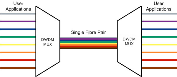
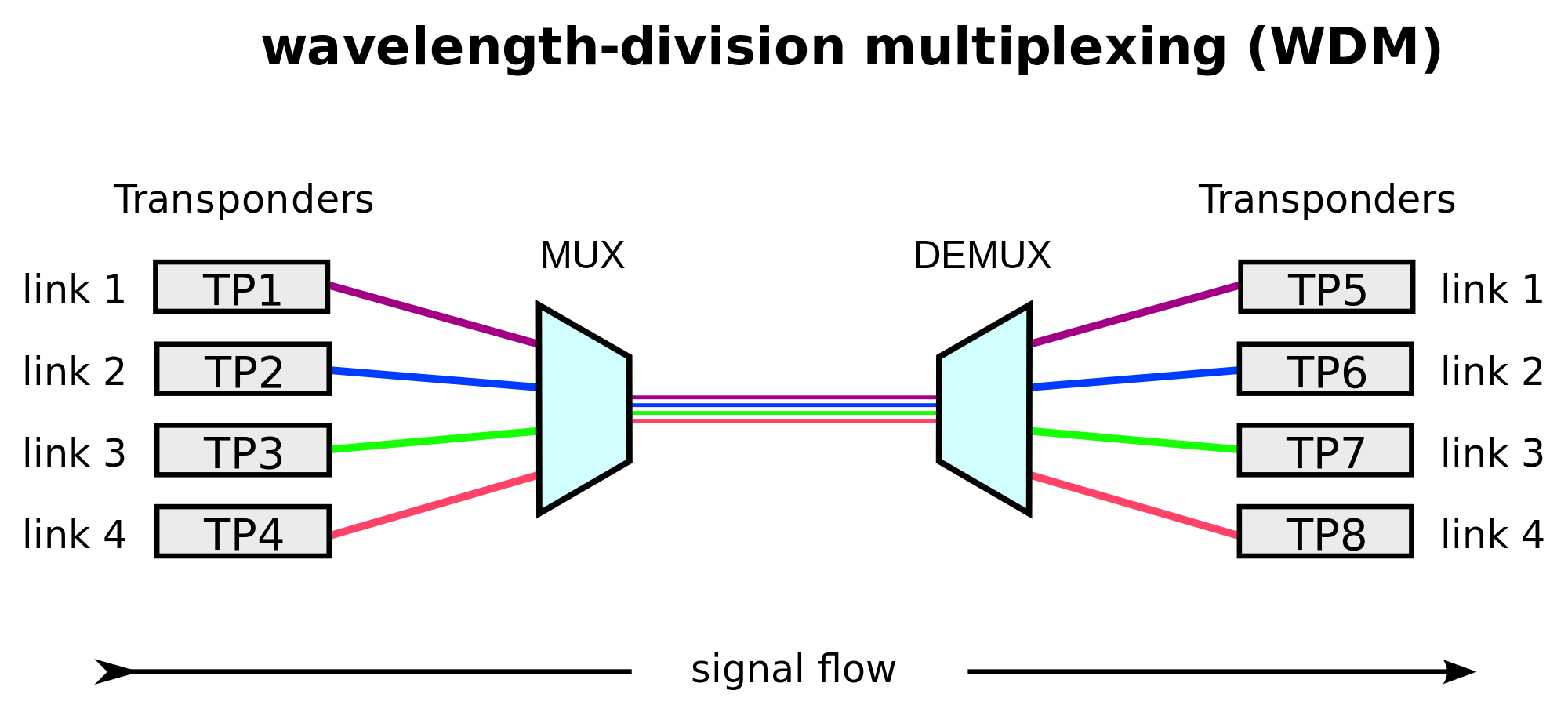
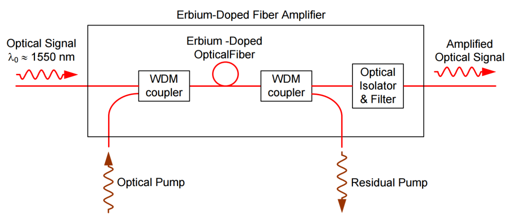
What is DWDM? DWDM stands for dense wavelength division multiplexing. It is a technology to send multiple strands of data through a single network link. In the transmitting end, there is an optical multiplexer converging two or more optical signals at different wavelengths. Whereas in the receiving end, an optical demultiplexer is used to separate the signals, and in this process it is unavoidable to cause signal loss which, however, can be mitigated by the optical amplifier. DWDM connections can therefore be used for transmitting data over long distances as it can increase bandwidth over existing fiber networks.

DWDM vs. OTN: DWDM Basics

DWDM Vs. OTN: OTN

OTN stands for optical transport network which provides a network-wide framework that adds SONET/SDH-like features like performance monitoring, fault detection, communication channels, and multiplexing hierarchy to WDM equipment. It works at Layer 1 to gather various tasks into the tunnel of WDM technology, increasing the transmission distance and capacity of fiber optics. It means that OTN frame structure combines the flexibility of SDH/SONET technology with the bandwidth expandability of DWDM, thus it can provide functionality of transport, multiplexing, routing, management, supervision, and survivability of optical channels carrying client signals.

The optical transport network is designed to deliver a transparent framework to efficiently carry diverse traffic types, which can decrease ACPEX/OPEX in networks and at the same time address dramatic shifts in traffic types. All in all, the charming of the OTN can be translated into two words: transparency and manageability.

Difference Between DWDM and OTN

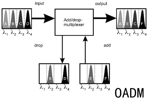
DWDM is a point-to-point system while OTN, composed of optical cross-connector (OXC) and optical add/drop multiplexer (OADM), possesses functions like optical cross-ability and wavelength conversion. The OTN grows on the basis of DWDM technology with the aim of optimizing the existing resources of transportation network. In addition to providing large capacities of DWDM transmission, OTN permits the switching of different DWDM channels according to the needs of traffic.

In addition, as it has been proven that it is possible to tap a fiber optic cable and extract data streams, people have paid much more attention to data security over DWDM links. In contrast, OTN-channelized links and effective partitioning of traffic onto dedicated circuits bring a high level of privacy and security, preventing hackers who sneak in some section of the network from intercepting data or gaining access to other areas.

We can say that OTN network excels DWDM networks in its enhanced OAM, security and networking capabilities for wavelengths and standard multiplexing hierarchy and end-to-end optical transport transparency of customer traffic.

Conclusion

DWDM vs. OTN, the topic being addressed in this article, makes sense for those who want to better utilize them and is worthy of being explored further. Though there are indeed differences between OTN and DWDM, the two technologies are irreplaceable and have become the key point in the telecommunications infrastructure for regional networks as the allows bandwidth over existing networks. FS focuses on providing customers the best technical support, engineering cost effective and scalable solutions for metro and long-haul DWDM network. For more details, visit this website.

OADM – Optical Add-Drop Multiplexer

With the development of optical communication technologies, people are entering into the new era of information. In order to overcome the data rate limitation of traditional communication system, WDM and OTDM technologies are typically used to increase fiber optic bandwidth. However, no matter which kind of technology is adopted to construct fiber optic network, optical add-drop multiplexer (OADM) technology is needed in the system. It makes the fiber optic network more flexible, optional and transparent. OADM is now a key component of the all-optical network to enhance the network reliability and efficiency. This article will give a brief introduction about the basic knowledge of OADM.

OADM

Definition of OADM

So what is an optical add-drop multiplexer or OADM? To be specific, an OADM is a device used in wavelength-division multiplexing systems for multiplexing and routing different channels of light into or out of a single-mode fiber. “Add” refers to the capability of the device to add one or more new wavelength channels to an existing multi-wavelength WDM signal. On the contrary, “drop” refers to its ability of removing one or more channels and passing those signals to another network path.

There are three parts of a traditional OADM – an optical demultiplexer, an optical multiplexer and a reconfiguration method between the demultiplexer and the multiplexer. The demultiplexer separates wavelengths from an input fiber onto different ports. The multiplexer multiplexes the wavelength channels that come from demultiplexer ports with those from the add ports onto a single output fiber. The reconfiguration can be achieved by a fiber patch panel or by optical switches which direct the wavelengths to the multiplexer or to drop ports.

Operating Principle of OADM

The WDM signal contains multiple wavelength channels. When these wavelengths enter into the main input of OADM, they can be selected to enter the drop output ports according to your application requirements. Correspondingly, the add ports will input the required wavelength channels. And those irrelevant wavelengths will directly pass through OADM and then be multiplexed with the added wavelengths together leaving the main output. Therefore, the function of OADM is to download necessary local signals and upload signals for the user of next node.

OADM-operating-principle

Two Kinds of OADM

Fixed OADM and reconfigurable OADM are two commonly used types of OADM. The former is used to drop or add data signals on dedicated WDM channels, and the latter is used to electronically alter the selected channel routing through the optical network.

Fixed OADM or FOADM is the traditional construction of OADM. It uses a filter to select a dropping wavelength and a multiplexer to add a new channel at the same wavelength. Different from FOADM, reconfigurable OADM or ROADM is a dynamic type which has the ability to remotely switch traffic from a WDM system at the wavelength layer. It provides flexibility in rerouting optical streams, avoids faculty connections, and allows minimal service disruption and the ability to adapt or upgrade the optical network to different WDM technologies.

Conclusion

OADM is an important element of an optical fiber network. It can be both deployed for long-haul core networks or short metro networks. Fixed OADM and reconfiguration OADM are two commonly used types. A further development of OADM is absolutely the future trend in fiber optic communications.

Comparison Between CWDM & DWDM Technology

For a better signal transmission in fiber-optic communication, different kinds of technologies are applied to the industry. Wavelength-division multiplexing (WDM) is one of the commonly used technologies which multiplexes a number of optical carrier signals onto a single optic fiber by using different wavelengths of laser light. That is to say, WDM enables two or more than two wavelength signals to transmit through different optical channels in the same optical fiber at the same time.

WDM

In the WDM system, there are two types of divisions – CWDM (coarse wavelength division multiplexing) and DWDM (dense wavelength division multiplexing). They are both using multiple wavelengths of laser light for signal transmission on a single fiber. However, from the aspects of channel spacing, transmission reach, modulation laser and cost, CWDM and DWDM still have a lot of differences. This article will focus on these distinctions and hope you can have a general understanding about CWDM and DWDM technology.

Channel Spacing

As their names suggest, the words “coarse” and “dense” reveal the difference in channel spacing. CWDM has a wider spacing than DWDM. It is able to transport up to 16 wavelengths with a channel spacing of 20 nm in the spectrum grid from 1270 nm to 1610 nm. But DWDM can carry 40, 80 or up to 160 wavelengths with a narrower spacing of 0.8 nm, 0.4 nm or 0.2 nm from the wavelengths of 1525 nm to 1565 nm (C band) or 1570 nm to 1610 nm (L band). It is no doubt that DWDM has a higher performance for transmitting a greater number of multiple wavelengths on a single fiber.

CWDM-VS-DWDM

Transmission Reach

Since the wavelengths are highly integrated in the fiber during light transmission, DWDM is able to reach a longer distance than CWDM. The amplified wavelengths provide DWDM with the ability of suffering less interference over long-haul cables. Unlike DWDM system, CWDM is unable to travel unlimited distance. The maximum reach of CWDM is about 160 kilometers but an amplified DWDM system can go much further as the signal strength is boosted periodically throughout the run.

Modulation Laser

CWDM system uses the uncooled laser while DWDM system uses the cooling laser. Laser cooling refers to a number of techniques in which atomic and molecular samples are cooled down to near absolute zero through the interaction with one or more laser fields. Cooling laser adopts temperature tuning which ensures better performance, higher safety and longer life span of DWDM system. But it also consumes more power than the electronic tuning uncooled laser used by CWDM system.

Cost

Because the range of temperature distribution is nonuniform in a very wide wavelength, so the temperature tuning is very difficult to realize, thus using the cooling laser technique increases the cost of DWDM system. Typically, DWDM equipment is four or five times more expensive than CWDM equipment.

Conclusion

CWDM and DWDM are both coming from the WDM technology that is capable of conveying multiple wavelengths in a single fiber. But with different characteristics, people should think twice before choosing the CWDM or DWDM system. CWDM usually costs less but its performance is far behind DWDM. Both your requirements and budget need to be taken into consideration. Moreover, the WDM products including CWDM mux/demux module, DWDM mux/demux module and optical splitter are highly welcome in the market.

EDFA Selection Guide

An EDFA is an optical amplifier based on Erbium-doped optical fiber, that amplifies optical signals without converting them into electrical form. EDFAs use semiconductor lasers to pump Erbium Doped Fiber to amplify light in 1.5 μm wavelength region where telecom fibers have their loss minimum. It has low noise and can amplify many wavelengths simultaneously, which makes DWDM network possible and becomes a key enabling technology for optical communication networks. Since the realization of EDFA, it has developed rapidly and has become the amplifier choice for most applications in optical communication.

Basic of EDFA

The structure and working principle of an EDFA are simple. EDFA consists of a glass optical fiber doped with Erbium ions, WDM coupler, isolators, optical filter and pumping supply.EDFA

The picture above shows how an EDFA works. When a beam of light that carrying signals passes the Erbium-doped optical fiber, a pump laser provides the amplifier energy at Erbium absorption peaks of 980 and 1480 nm, through the use of WDM couplers. Then an optical filter removes the remaining traces of the pump beam so that it doesn’t interfere with reception of the signal. Isolators are inserted into the amplifiers to minimize the reflections on the EDFA

How to Choose the Right EDFA

First of all, you should make sure the network type in which you need to use EDFA. Depending on the network application, EDFA are generally designed into the following types:

  • DWDM EDFA: for this type of network, EDFA needs to be not only high power low noise, but also gain flattened such that all wavelength channels can be amplified equally.
  • SDH EDFA: For SDH network, EDFA design should allow maximum power budget to achieve the highest detection sensitivity.
  • CATV EDFA: There is also EDFA designed for CATV application, which has low noise with heat dissipation and ventilation in mind to ensure a long operation life.

The way in which EDFA used is to enhance the performance of optical data links is also important in selecting EDFAs. Depending on this, three types of EDFAs can be found in the market:

  • Booster EDFA: this EDFA is used to increase the optical output of an optical transmitter just before the signal enters an optical fiber.
  • Inline EDFA: as the optical signal is attenuated as it travels in the optical fiber. The inline amplifier is used to restore the optical signal to its original power level.
  • EDF pre-amplifier: this kind of EDFA is used at the end of the optical link in order to increase the sensitivity of an optical receiver.

Some other important elements should be considered before selecting EDFAs.

  • Wavelengths: you should make certain how many wavelengths will go through the EDFA and the beginning and ending wavelengths, for example 1530 to 1562 nm. For single wavelength link, you should know clearly the exact wavelength.
  • Power or loss budget: the budget tells us how much amplification you require for the whole link.
  • The location of EDFAs: After the transmitter, before the receiver, or in the mid-span.

Fiberstore DWDM EDFASelecting the right EDFA seems not an easy thing. However, if you are not sure about the types and numbers of EDFAs, you can visit FS which supplies various EDFAs with high quality and low price, as well as free EDFA solutions meeting customers’ requests.

Do Not Miss FS’s 40-Channel DWDM Multiplexer/Demultiplexer with the Lowest Price

DWDM (Dense Wavelength Division Multiplexing), an ideal optical multiplexing technology for long-haul data transporting, can put multiple channels of information using individual wavelength on the same fiber and increase the transmission capacity of optical networks considerably. Currently, DWDM technology is being widely applied in telecommunication networks and becomes the choice of many telecommunication operators.

Since the start of DWDM, various equipment and technologies have been used to enhance the high performance of every part of DWDM network. DWDM Multiplexer and demultiplexer are the main equipment that takes charge of the data sources’ multiplexing and demultiplexing. In the past years, DWDM multiplexers and demultiplexers have been upgraded rapidly to overcome the insertion loss and to meet the demands of the increasing requests for faster telecommunication, and they are always being combined in one rack by today’s vendors also known as DWDM Mux/Demux.

FS as a serious manufacture of optical communication published a 40-channel Duplex DWDM Athermal AWG Mux/Demux with competitive features which are described as following.

Fiberstore 40-channel DWDM Mux/Demux

Low Insertion Loss: Insertion loss is an inevitable problem in optical networks. Combining LC/UPC connectors of high quality and AWG technology, this duplex Mux/Demux reduces the insertion loss to a minimum of 3dB and increases the transmission capacity effectively.

Athermal AWG Technology: With athermal design this mux/demux device is temperature-intensive and allows multiplexing and demultiplexing of DWDM signals over a wide operating temperature range with long-term stability, reliability and large transmission capacity.

Large Channel Number & Excellent Channel Isolation: This DWDM Mux/Demux is designed for use within the C-band release of DWDM system which uses 40 channels at 100GHz spacing containing the channels from C21 (wavelength: 1560.606 nm) to C60 (wavelength: 1529.553 nm). Also 1.6nm (200 GHz) are available on request. Excellent channel isolation that eases the fiber handling is also provided.

Space-saving: With a standard 19-inch rack mount housing size, this DWDM Mux/Demux saves space effectively.

High quality and Inexpensive: The products of FS has been appreciated by customers for its reliable quality. Comparing with other manufactures, FS offers the lowest price for such a high quality 40-channel DWDM Mux/Demux.

40-Channel DWDM Mux/Demux

For detailed specifications of this low insertion loss 40-channel Duplex DWDM Athermal AWG Mux/Demux with Monitor Port, please visit FS’s online shop. FS currently has 10 of this DWDM Mux/Demux in stock and can deliver on the same day of ordering. FS also provides a custom package to meet customers’ requirements.

Cost-effective Capacity Growth and Investment Protection — Hybrid DWDM/CWDM

Introduction of Hybrid DWDM-CWDM

CWDM is an excellent, cost-effective, first step solution for scaling metro networks. Low cost hybrid DWDM-CWDM modules can support up to 8 channels at 2.5 Gbps. This is sufficient for many networks in the metro space. If capacity needs grow beyond 8 channels, these modules can be used to merge DWDM and CWDM traffic seamlessly at the optical layer. This allows carriers to add many channels to networks originally designed for the more limited CWDM capacity and reach.

Hybrid DWDM-CWDM technology delivers true pay-as- you-grow capacity growth and investment protection. It offers a simple, plug-and-play option for creating hybrid systems of DWDM channels interleaved with existing CWDM channel plans.


Advantages of Hybrid DWDM-CWDM

The major advantages of hybrid DWDM-CWDM for carriers are as following:

  • Reduced Cost: CWDM has a significant cost advantage over DWDM due to the lower cost of lasers and the filters used in CWDM modules (CWDM MUX, CWDM OADM etc.). Coarse channel spacing allows more tolerance for channel deviations or wavelength deviations. Therefore, CWDM filters and transmitters are easier, and cheaper, to manufacture. This cost saving becomes quite significant for large deployments.
  • Pay-As-You-Grow: Adding new channels one at a time allows for on-demand service introduction with minimal initial investment, a critical feature in times of reduced OPEX and CAPEX spending.
  • Investment Protection: Although 8 channels may be enough in an initial deployment, it’s important to have an upgrade path to avoid a forklift upgrade to DWDM when growth in demand finally requires significant new capacity. Given the DWDM over CWDM upgrade capability, carriers no longer have to choose between CWDM and DWDM—both options can be deployed simultaneously or as part of a planned future, or incremental, upgrade. Hybrid DWDM-CWDM modules can be used in either the DWDM systems or in the CWDM systems. Current capital investment can always be used in the upgraded network.

Theory of DWDM/CWDM Hybridization

The CWDM frequency grid consists of 16 channels spaced at 20 nm intervals. The eight most commonly used channels are: 1470 nm, 1490 nm, 1510 nm, 1530 nm, 1550 nm 1570 nm, 1590 nm and 1610 nm. Within the pass band of these channels there exists the capacity to add twenty-five 100 GHz spaced DWDM channels under the 1530 nm envelope and twenty-five more under the 1550 nm envelope if the filter is properly designed. The theoretical availability of DWDM channels in the 1530 nm and 1550 nm pass-band is shown in the table below.

Theoretical DWDM Channels in the 1530 and 1550 nm CWDM Pass-Band


Practical Application of DWDM/CWDM Hybridization

In practice, adding another 25 DWDM channels in the pass-band of both the 1530 nm and 1550 nm CWDM channels is not achievable because the optical filters are not perfect square functions. The actual filter profile affects the number of channels which can be accommodated. However, actual DWDM filter technology does allow 38 additional channels to clear the CWDM archway as shown in the table below.

Actual DWDM Channels in the 1530 and 1550 nm CWDM Pass-Band

The system impact to adding these channels is equivalent to adding the component in line with existing CWDM equipment. The insertion losses add linearly. Here is a figure that shows the infrastructure in a fully populated CWDM system.

Infrastructure of Hybrid DWDM CWDM System

To add more channels to MUX side of this network, one would plug in a DWDM MUX with the appropriate channels to fall under the pass-band of the existing CWDM filters. The figure below shows the infrastructure of a CWDM system upgraded with 38 additional 100 GHz spaced DWDM channels.

44-Channel Hybrid DWDM-CWDM System

The number of channels present in this hybrid system is 38 DWDM channels plus the existing 6 CWDM channels for a total of 44. The equipment required to go from the first architecture to the second are 2 DWDM multiplexers and demultiplexers, as well as the additional transmitter and receiver pairs required. The additional loss incurred by the upgrade is equal to the additional loss of the DWDM elements and the additional connection points.

Several network types could take advantage of the hybrid architecture. For example, one could increase the capacity of an existing ring by deploying all of the elements above at each node. Or, one could allow DWDM traffic to overlay an existing CWDM network at a pre-determined crossover point.

The two networks would be configured in such a way to allow the DWDM traffic to travel across the CWDM ring. All of the nodes where the DWDM traffic would travel on the CWDM ring would require the DWDM multiplexer and demultiplexer pairs (shown as below).

Hybrid CWDM-DWDM Rings

Another application for the DWDM channels is for long reach links in CWDM rings. If a certain span exists in a CWDM network with a large distance between regenerators, e.g. 100 km, DWDM channels can be used in place of CWDM ones to overcome this distance. The figure below shows a hybrid DWDM-CWDM mixed node.

CWDM-DWDM Mixed Node

System Impact

The added components on the CWDM ring will decrease the link budget for each span by the amount of insertion loss for each new component. The use of high isolation optical filters for the DWDM channels will ensure that cross talk is minimized between closely spaced channels. In the case of very high channel counts, non-linear effects should be taken into consideration. These include self phase modulation and Four-Wave Mixing (FWM).

The lasers used in DWDM networks have a much narrower line width than lasers used in CWDM. As a result the DWDM signals will typically have farther reach, and will undergo less pulse broadening due to chromatic dispersion. However they also lie within the operating range of Erbium-Doped Fiber Amplifier (EDFA). This means that DWDM signals can go un-regenerated for large distances. This limit is reached at the transmitter’s dispersion limit.

Receiver technology is independent of the optical signal present. The same receiver can be used to resolve a CWDM signal as well as a DWDM signal. The InGaAs material used to convert the optical signal into an electrical one has an operating range that includes both wavelength schemes. In the case of a 3R receiver, the receiver should be chosen such that it is compatible with the transmitter’s data rate.

Article Source: http://www.fs.com/blog/cost-effective-capacity-growth-and-investment-protection-hybrid-dwdmcwdm.html

Dual Stage EDFA with DCM Mid-Stage Access – DCM-optimized EDFA

Besides optical amplifiers, modern optical networks also require other components to be place along the link, such as the Dispersion Compensation Module (DCM) used to correct signal distortion due to Chromatic Dispersion of the transmission fiber. Since the attenuation of DCM can be quite large, in the range of 5 to 10 dB, additional amplification is needed to accommodate them. In order to minimize the Optical Signal Noise Ratio OSNR and cost impact of this addition amplification, it is beneficial to place the DCM between two amplifiers.

A dual stage EDFA amplifier is basically two amplifiers in one package, where there is access for an optical component such as a DCM to be placed between them. In this configuration, it is called a DCM-optimized EDFA. Most often the first amplifier (pre-amplifier) is variable gain, and the second (booster amplifier) is fixed gain, such that the amplifier as a whole provides variable gain operation. The control of both amplifiers is combined, in other words the user sets the required net gain of the entire combination (including the DCM), and the control units sets the gain of each of the two amplifier in order to achieve the net gain.

Note: DCM-optimized EDFA is named because of using DCM as the mid-stage access. The DCM EDFA can be generally provided as a stand-alone module or in a managed 1RU package with the DCM integrated within. Fiberstore’s Dual Stage DCM-optimized EDFA is a stand-alone module without the DCM which need to be bought separately. In this way, customers could choose the right dispersion compensation modules to meet their own requirements.

DCM-optimized EDFA

Dispersion Compensation Module (DCM)

Here is the basic scheme for a dual stage EDFA amplifier with DCM mid-stage access. The two amplifiers are packaged in the same module and are controlled together with the mid-stage device (i.e. the DCM) as a single unit. Additionally, each amplifier also has its own local control loops.

Dual Stage EDFA with DCM Mid-Stage Access

The amplifiers are designed apriori to take into account the DCF loss. For example, the dynamic range of the input detectors of both amplifiers is set accordingly, and the optical performance, such as Noise Figure (NF), is specified already taking the DCM loss into account. Since the DCM is often implemented using special Dispersion Compensation Fiber (DCF), there can be a large optic al delay between the first and the second stage of the amplifier. For this reason transi ent suppression of each amplifier ne eds to be performed separately, and consequently each amplifier has its own pump and own local control mechanism (in addition to the overall control used to set the net gain).

Fiberstore Coarse Wavelength Division Multiplexing Devices

CWDM mux/demux is a flexible solution that enables operators make full use of available fiber bandwidth in local loop and enterprise architectures. The wavelengths used with CWDM implementations are defined by the ITU-T G.694.2, listing 18 wavelengths from 1270nm to 1610nm with 20nm increased. CWDM solution takes the most important advantage of low price which is typically 1/3rd lower than the equivalent DWDM optics. FS.COM introduces its new generation of coarse wavelength-division multiplexing (CWDM) devices boasting increased functions and improved performance to extend the reach of CWDM metropolitan networks. The following text will introduce CWDM Mux/Demux, CWDM OADM, and optical port configuration used in CWDM network.

FS.COM CWDM MUx/Demux

The CWDM Mux/Demux in FS.COM is a universal device capable of combining up to 18 optical signals into a fiber pair or 9 optical signals into a single fiber. It is designed to support a broad range of architectures, ranging from scalable point-to-point links to two fiber-protected rings.

Besides, FS.COM CWDM Mux/Demux is a passive device which allows for any protocol to be transported over the link, as long as it is at a specific wavelength (i.e. T1 over fiber at 1570nm transported alongside 10Gbps Ethernet at 1590nm). This allows for long-term future proofing of the networking infrastructure because the multiplexers simply refract light at any network speed, regardless of the protocol being deployed. The following image shows FS.COM 8 Channels 1470-1610nm Dual Fiber CWDM Mux Demux.

8 Channels 1470-1610nm Dual Fiber CWDM Mux Demux

FS.COM CWDM Mux/Demux With Different Optional Port Configurations

FS.COM also provides CWDM Mux/Demux with different optional port configurations such as, express port, monitor port, 1310nm pass band port and 1550nm port for these multiplexers according to customer choice.

  • Monitor Port: Our CWDM Mux/Demux is optional to equip with monitor port that allows our customer connect optical meter or OSA to monitor and troubleshoot the network. It is simple to operate. Add the monitor port to an existing, multiplexed link. A small sample, of each signal, is “leaked” to the outputs, then connect measurement/monitoring equipment, such as power meters or network analyzers, to the module outputs. When finished monitoring, disconnect the instruments. The network is left undisturbed. (Monitor port tap percentage is 5% as default.)
  • Expansion/Express Port: The Expansion Port (EXP) enables the cascading of two CWDM Mux/Demux modules, doubling the channel capacity on the common fiber link. For example, two 4-Channel MUX/DEMUX modules can be cascaded to create an 8-Channel fiber common link. (Express port isolation is 15dB as default.)
  • 1310 Pass Band Port: The 1310 pass band port allows a legacy 1310nm signal to pass through the CWDM MUX DEMUX module. The port can be used to combine an existing legacy 1310nm network with CWDM channels, allowing the CWDM channels to be overlaid on the same fiber pair as the existing 1310nm network. (Note: When you choose 1310nm pass band port, the CWDM 1310nm wavelength channel is NOT available on the CWDM MUX modules.) Besides, the 1310nm port can be used in this way as an optical supervisory channel (OSC) and its range is 1270nm-1350nm (1310nm±40nm). (Note: When you choose 1310nm pass band as an OSC, the available range of wavelength is 1370nm~1610nm on the CWDM MUX modules.)
  • 1550 pass band port: The 1550 pass band port allows a legacy 1550nm signal to pass through the CWDM Mux/Demux module. The 1550nm port can also be used in this way as an optical supervisory channel (OSC) and its range is 1510nm-1590nm (1550nm±40nm). When you choose 1550nm pass band as an OSC, the available range of wavelength is 1270nm~1490nm on the CWDM MUX modules.

Note: that standard (or native) 1310nm and 1550nm wavelengths are not the same as CWDM 1310nm and CWDM 1550nm wavelengths. The center wavelength tolerances for legacy 1310nm and 1550nm are much wider than the CWDM equivalents, and therefore not precise enough to run through CWDM filters. When implementing a CWDM network, a standard wavelength can be converted to CWDM wavelength, or a CWDM Mux with a pass band port can overlay the standard wavelength onto the CWDM common link. A pass band port is an additional channel port on a CWDM MUX that allows a legacy 1310nm or 1550nm signal to pass through the network within a reserved band. The legacy device is connected directly to the pass band port via fiber cabling. Standard wavelengths can be converted to CWDM wavelengths using CWDM Small Form Pluggable (SFP) transceivers, transponders, and media converters that support SFPs.

FS.COM CWDM OADM

Since adding new fiber optic cables for signal transmission of the devices would cost too much, IT managers would turn to use OADM in CWDM network, which can couple two or more wavelengths into a single fiber as well as the reverse process, saving a lot of money and installation time when they want to add or drop signal on a single fiber. FS.COM provides a wide selection of CWDM OADM which can add or drop fiber count of 1, 2 and 4. And these OADMs can be categorized into three type with different package form factors: plug-in module, pigtailed ABS box and rack mount chassis. The plug-in modules can be installed in empty rack enclosures. Three CWDM OADM types with different package form factors are shown below.

plug-in module, pigtailed ABS box and rack mount chassis

Conclusion

CWDM is a popular technology which can provide cost-effective solutions for users to upgrade their network using the least fiber strands. FS.COM provides a series of devices used in CWDM network, like CWDM Mux/Demux with different optical port configurations, CWDM OADMs, CWDM transceiver modules, etc. For any requirement, please visit FS.COM.