Considering Three Aspects Before Migrating to 40G Ethernet

The dramatic growth of bandwidth requirements in data centers has led to the worldwide use of higher-performance optical products for network scalability, management, flexibility and reliability. Currently, 10GbE (Gigabit Ethernet) can’t meet the increasing needs of high speed transmission well for such applications as Big Data, cloud and Internet of Things being introduced in many industries. As such, network migration to 40G Ethernet has already been the industry consensus.

But as the cost for 100G is far beyond what most enterprises can afford and the technology for 100G is still not mature enough, 40G Ethernet has been a better solution for its lower cost and maturer technologies compared to 100G. Nowadays, some manufacturers are battling for the 40G Ethernet market, which drives down the 40G Ethernet deployment price, leading to the even wider deployment of 40G Ethernet infrastructure. When migrating from 10G to 40G, three aspects should be considered: fiber optic transceiver, transmission media, and pre-terminated MPO assemblies.

Fiber Optic Transceiver 

For any telecommunication network, fiber optic interconnection is of great importance. Photoelectric conversion is a necessary part in fiber optic network. The function of fiber optic transceiver is photoelectric conversion, which makes it one of the most commonly used components in the data center.

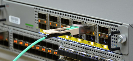
As for 40G transceivers, two different package forms are available: QSFP+ (Quad Small Form-factor Pluggable Plus) and CFP (C Form-factor Pluggable), with the former more widely-used than the latter. A single 40G fiber optic transceiver may not be expensive. But what a medium-sized data center needs is thousands of optical transceivers, meaning a large sum of money to be spent. In such a case, third party transceivers that are compatible with a variety types of switches come into point. They have the same performances that the original brand transceivers have, but cost less money. When selecting 40G compatible transceivers, cost and quality are very important. Choosing the compatible 40G transceivers from Fiberstore can ensure 100% compatibility and interoperability. The picture below shows the testing of Cisco compatible QSFP-40G-SR4 transceivers on a Cisco switch to ensure its compatibility and interoperability.

QSFP-40G-SR4 for 40G ethernet

Transmission Media

Allowing for several situations that may exist, the IEEE 802.3ba specified the different transmission media for 40G links, including the following listed media:

  • 40GBASE-CR4: 40Gb/s Ethernet over copper cable in short transmission distance.
  • 40GBASE-SR4 (eg. QFX-QSFP-40G-SR4): 40Gb/s Ethernet over four short-range multi-mode fiber (MMF) optic cables.
  • 40GBASE-LR4: 40Gb/s Ethernet over four wavelengths carried by a signal long-distance single-mode fiber (SMF) optic cable.

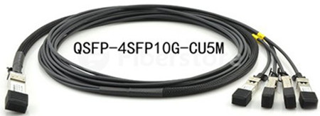
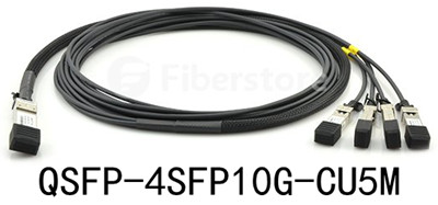
There also exists hybrid cabling solutions for 40G applications, like QSFP to 4SFP+ breakout cabling assembly. Take QSFP-4SFP10G-CU5M for example, this product listed in Fiberstore is the QSFP+ to 4 10GBASE-CU SFP+ passive direct-attach copper transceiver assembly with 5-meter reach.

QSFP to 4SFP+ breakout cabling assembly, for short reach, 5m

Question occurs: fiber optic cable or copper cable, which should be used in 40G migration? Copper is cheaper. But it can only support 40G transmission limited to several meters. SMF supports the longest 40G transmission distance up to 40 km. As for MMF, OM3 and OM4 are suggested to support short distance transmission. The longest distance that OM3 can support for 40G transmission is 100 m. OM4 can support a longest 40G transmission distance of 150 m. The selection of transmission media should depend on the specific applications.

MPO Assemblies for 40G

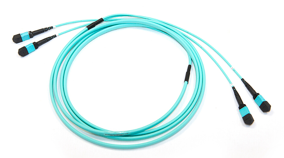
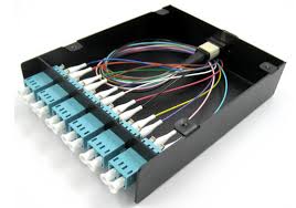
The IEEE 802.3ba standard also specifies multi-fiber push-on (MPO) connectors for standard-length MMF connectivity. Most of the 40G multi-mode Ethernet transceivers are based on the MPO technology. It is wise to increase fiber optic density by using MPO technology, but a new problem arises. As the fiber number increased, the cabling and splicing difficulty in data center increased. Unlike traditional two-strand fiber connections, MPO connectors cannot be field terminated easily. Thus, most of the data centers choose the pre-terminated MPO assemblies in 40G deployment, which is more reliable and can save more human labor. Before cabling, determine the cabling lengths and customized pre-terminated MPO assemblies with manufacturers would save a lot of time and money.

Conclusion

Using compatible third party transceivers of high quality for 40G Ethernet links saves a lot of money. Taking specific applications and characteristics of 40G transmission media into consideration can also help you to save cost. Pre-terminated MPO assemblies are necessary for flexible and manageable cabling in 40G deployment. With these information in mind, cost-effective 40G Ethernet migration is at the corner.

In-depth Understanding of Fiber Optic Cables

The commitment to fiber optic technology has spanned more than 30 years, and nowadays a high level of glass purity, fiber optic cable, has been achieved owing to the continuous research and development. This purity, combined with improved system electronics, enables to transmit digitized light signals over hundreds of kilometers with high performance, offering many advantages in fiber optic systems. This text provides an overview of the construction, categories, and working principles of this fiber optic cable.

Construction of Fiber Optic Cable

Fiber optic cable generally consists of fiver elements : the optic core, optic cladding, a buffer material, a strength material and the outer jacket. Here, much more detailed information is attributive to the optic core and optic cladding which are both made from doped silica (glass).

The Optic Core and Cladding Details

The optic core is the light-carrying element at the center of the cable, and the optic cladding surrounds the optic core. Their combination makes the principle of total internal reflection possible. Besides, a protective acrylate coating then surrounds the cladding. In most cases, the protective coating is a dual layer composition: a soft inner layer that cushions the fiber and allows the coating to be stripped from the glass mechanically, and a harder outer layer that protects the fiber during handling, particularly the cabling, installation, and termination processes. This coating protects the glass from dust and scratches that can affect fiber strength.

Optic Core and Cladding, makes reflection possible

Categories of Fiber Optic Cable

There are two general categories of fiber optic cable: single-mode fiber (SMF) and multi-mode fiber (MMF).

MMF was the first type of fiber to be commercialized. It has a core of 50 to 62.5 µm in diameter much larger than SMF, allowing hundreds of modes of light to propagate through the fiber simultaneously. Additionally, the larger core diameter of MMF facilitates the use of lower-cost optical transmitters (such as light emitting diodes or vertical cavity surface emitting lasers) and connectors, more suitable for relatively shorter-reach application. Take 1 Gigabit Ethernet (GbE) applications for example, MMF is deployed to establish 550m link length with 1000BASE-SX SFPs (eg. Cisco Meraki MA-SFP-1GB-SX).

SMF, in contrast, has a much smaller core, approximately 8 to 10 µm in diameter, which allows only one mode of light at a time to propagate through the core. It’s designed to maintain spatial and spectral integrity of each optical signal over longer distances, permitting more information to be transmitted. Similarly, as for 1GbE applications, SMF is able to realize 70km reach with 1000BASE-ZX SFPs, like GLC-ZX-SM, a product compatible with Cisco listed in Fiberstore.

GLC-ZX-SM, 1000BASE-ZX SFP

Working Principles of Fiber Optic Cable

The operation of a fiber optic cable is based on the principle of total internal reflection. Light reflects (bounces back) or refracts (alters its direction while penetrating a different medium), depending on the angle at which it strikes a surface.

This principle comes at the center of how fiber optic cable works. Controlling the angle at which the lightwaves are transmitted makes it possible to control how efficiently they reach their destination. Lightwaves are guided through the core of the fiber optic cable in much the same way that radio frequency (RF) signals are guided through coaxial cable. The lightwaves are guided to the other end of the fiber being reflected within the core. The composition of the cladding glass related to the core glass determines the fiber’s ability to reflect light. That reflection is usually caused by creating a higher refractive index in the core of the glass instead of in the surrounding cladding glass, creating a waveguide. The refractive index of the core is increased by slightly modifying the composition of the core glass, generally by adding small amounts of a dopant. Alternatively, the waveguide can be created by reducing the refractive index of the cladding using different dopants.

Conclusion

In fiber optic cables, the light can carry more information over longer distances than the amount carried in a copper or coaxial medium or radio frequencies through a wireless medium. With few transmission losses, low interference, and high bandwidth, fiber optic cables are the ideal transmission medium. Fiberstore offers various kinds of fiber optic cables, including SMF and MMF types, simplex and duplex fiber optic cables, indoor distribution cables and outdoor loose tube cables, etc. For more information about fiber optic cables, you can visit Fiberstore.

FAQs About Laser-Optimized Fiber

Fiber optical networks have dominated for long-haul communications for years, increasingly used in short distance applications, such as local area networks (LANs). And the Ethernet data-rate needed for these high-performance fiber optic networks increases from 1Gbps to 10Gbps, to 40Gbps, to 100Gbps, or even higher. Together with this speed increase, a term, laser-optimized fiber, has crept into the telecommunication market. What is laser-optimized fiber? How much do you know about it? Knowing answers to these frequently asked questions (FAQs) about laser-optimized fiber will help you prepare for the latest wave in optical communication networks.

FAQ 1: What Is Laser-Optimized Fiber?

Laser-optimized multi-mode fiber (LOMMF: OM3 & OM4) differs from standard MMF (OM1 & OM2), because the former has graded refractive index profile fiber optic cable in each assembly. This means that the refractive index of the core glass decreases toward the outer cladding, so the paths of light towards the outer edge of the fiber travel quicker than the other paths. This increase in speed equalizes the travel time for both short and long light paths, ensuring accurate information transmission and receipt over much greater distances up to 300 meters (OM3) and 400 meters (OM4) at 10Gbps, while OM1 and OM2 can only realize 26 meters and 33 meters link length respectively at the same data rate. And when 1000BASE-SX SFP transceivers transmit and receive signals over LOMMF and standard MMF at 1Gbps, the possible link lengths achieved are also different, with OM1 275-meter reach, OM2, OM3, and OM4 up to 550-meter reach. Take MGBSX1 for example, this compatible Cisco 1000BASE-SX SFP listed in Fiberstore supports up to 550-meter link length over OM2.

MGBSX1, 550m link length over MMF

FAQ 2: Why Have MMF Been “Optimized” for Use with Lasers?

As the demand for bandwidth and higher throughput increased, especially in building and campus backbones, LEDs, short for Light Emitting Diodes, that are used as light sources in fiber optic systems could not keep pace. With a maximum modulation rate of 622Mb/s, LEDs would not support the 1 Gb/s and greater transmission rates required. The use of traditional lasers (Fabry-Perot, Distributed Feedback) typically used over single-mode fiber (SMF) could accommodate this problem. However, it’s very expensive due to the higher performance characteristics required for long-distance transmission on SMF. As such, a high-speed laser light source, a Vertical Cavity Surface Emitting Laser (VCSEL) was developed. These VCSELs are inexpensive, suited for low-cost 850nm multi-mode transmission systems, allowing for data rates up to 100Gbps in the enterprise. With the emergence of these VCSELs, MMFs have been “optimized” for operation with lasers.

FAQ 3: Why Are LOMMFs the Best Choice for Use with VCSELs?

After VCSELs appears, to fully capitalize on the benefits that VCSELs offer, LOMMFs have been specifically designed, fabricated, and tested for efficient and reliable use with VCSELs.

LOMMF,specifically designed, fabricated, and tested

LOMMFs have a well-designed and carefully controlled refractive index profile to ensure optimum light transmission with a VCSEL. Precise control of the refractive index profile minimizes the modal dispersion, also known as Differential Mode Delay (DMD). This ensures that all modes, or light paths in the fiber arrive at the receiver at about the same time, minimizing pulse spreading and, therefore, maximizing bandwidth.

LOMMF is completely compatible with LEDs and other fiber optic applications. LOMMFs can be installed at slower data rates or higher data rate. When there occurs the data rate migration from 10Gbps to 40Gbps, there is no need to pull new cable. You only need to upgrade the optics modules to VCSEL-based transceivers, avoiding infrastructure redesign.

Conclusion

LOMMFs are the suitable medium for short-wave 10G optical transmission. Their great bandwidth- and information-carrying capacity make them more popular among consumers than standard MMFs especially in 10GbE systems. Fiberstore supplies countless OM3 and OM4, as well as OM1 and OM2 for your network projects. Besides, other kinds of fiber optic cables, like MTP cable and SMF, are also available in Fiberstore. For more information about fiber optic cables, please visit Fiberstore.

Pluggable Optical Transceiver Used in Data Centers

Today’s data centers are going through unprecedented growth and innovation as emerging optical standards and customers’ demands for higher-level networking services converge. Bandwidth, port density and low-power demands come as the main drivers that populate the deployment of fiber optic networks. And in fiber optic network implementations, pluggable optical transceiver provides a modular approach to safe-proof network design and become the ideal choice to meet the ever-changing network needs in data centers. This text just mainly introduces pluggable transceivers deployed in data centers.

A Quick Question: What Are Pluggable Optical Transceiver?

Pluggable optical transceivers are transceivers that can be plugged into routers, switches, transport gear, or pretty much any network device to transmit and receive signals. They are hot swappable while the device is operating, standardized to be interchangeable among vendors, capable of operating over many different physical medium and at different distances. For instance, pluggable optical transceiver can work through copper, through fiber optic cables available in both singlemode fibers (SMFs) and multimode fibers (MMFs), realizing 100m, 300m, 10km, 80km distance reach, etc. In addition, these hot-swappable transceivers are also able to support a wide variety of speeds, like 1Gbit/s, 10Gbit/s, 40Gbit/s, 100Gbit/s, or even higher.

Pluggable Optical Transceiver – Standards & Protocols

Just as what has been mentioned above, pluggable optical transceivers are interchangeable. These interchangeable transceivers allow a single device to operate with a wide selection of protocols and functions. Listed below are commonly-used pluggable transceiver standards and protocols.

SFP—The small form-factor pluggable (SFP) supports a wide range of protocols and rates, such as Fast and Gigabit Ethernet (GbE), Fibre Channel (FC), and synchronous optical networking (SONET) for dual and bidirectional transmission. SFP medium are available in SMF, MMF, and copper. For MMF media, there exists 1000BASE-SX port type used in 1GbE applications. Take J4858C for example, this HP 1000BASE-SX SFP can realize a maximum of 550m reach at 1.25 Gbit/s over MMF.

HP 1000BASE-SX SFP optical transceiver

SFP+—The enhanced small form-factor pluggable (SFP+) is an enhanced version of the SFP, supporting data rates up to 16Gbit/s. It was first published on May 9, 2006, and version 4.1 was published on July 6, 2009, supporting 8Gbit/s FC, 10GbE and Optical Transport Network standard OTU2. SFP+ is a popular industry format supported by many network component vendors.

XFP—The XFP (10G SFP) is a standard for transceivers for high-speed computer network and telecommunication links that use optical fiber. Its principal applications include 10GbE, 10Gbit/s FC, SONET at OC-192 rates, synchronous optical networking STM-64, 10 Gbit/s Optical Transport Network (OTN) OTU-2, and parallel optics links.

QSFP—The Quad Small Form-factor Pluggable (QSFP) is a also a compact, hot-pluggable transceiver used for data communications applications. QSFP+ transceivers are designed to carry Serial Attached SCSI, 40GbE (100G using QSFP28), QDR (40G) and FDR (56G) Infiniband, and other communications standards. They increase the port-density by 3x-4x compared to SFP+ modules. In 40GbE applications, these QSFP+ transceivers establish 40G links with distances up to 300m over MMF, and 40km over SMF. QSFP can also take copper as its media option when the required distance is short. Like QSFP-4SFP10G-CU5M, this product is the QSFP to 4 10GBASE-CU SFP+ direct attach passive copper cable assembly designed for relatively short reach, that is 5m. The image below just shows what this QSFP-4SFP10G-CU5M product looks like.

QSFP-4SFP10G-CU5M, QSFP to 4 10GBASE-CU SFP+

CFP—The C form-factor pluggable (CFP) is a multi-source agreement (MSA) to produce a common form-factor for the transmission of high-speed digital signals. The c stands for the Latin letter C used to express the number 100 (centum), since the standard was primarily developed for 100 Gigabit Ethernet systems.

Conclusion

Pluggable  optical transceivers offer distance extension solutions, allowing flexibility in network reach and easy replacement in the event of component failures. They are the answer to today’s network architecture and performance demands. FS.COM supplies various pluggable optical transceivers supporting different speeds, like SFP (J4858C), SFP+, XFP, QSFP, CFP, etc.

How Transceiver Module Helps to Support Big Data in Data Centers?

Today’s data centers need to better adapt to virtualized workloads and the ongoing enterprise transition to hybrid clouds, since business owners always rely on big date technology to get timely information and make immediate decisions. Transceiver module, one of the most critical designs in telecommunication field, is related to the promotion of big data in data centers, helping business owners get their data in real-time. This just explains the importance of being aware of the three ways in which transceivers help support big data in data centers.

Transceiver Module Facilitates High Speed Data Transfers

A growing number of enterprises are transiting to private and hybrid clouds, which drives the bandwidth and connectivity requirements. As high-speed data carrier, transceivers facilitate high speed data transfers. Enterprises that want to achieve faster transmission have to choose transceivers with high quality. There are many types of transceivers available in the market, such as SFP, SFP+, XFP, QSFP, etc. Each type of transceiver is designed to support different data rate. Capable of transmitting data at 10Gbit/s, 40Gbit/s, 100Gbit/s or even 120 Gbit/s, transceivers can realize the high-speed data transfer, ensuring bandwidth upgrades in enterprise data centers. Take 10GBASE SFP+ modules for example, these hot-pluggable transceivers (eg. SFP-10G-SR) deployed for 10 Gigabit Ethernet (GbE) applications, though designed physically small, can handle fast transmission with the maximum data rate of 10.3125Gbps.

SFP-10G-SR, handles fast transmission

Transceiver Module Promotes Data Transmission Process in Data Centers

Enterprise that need to manage big data can benefit from the use of transceivers. Data centers are places where enterprises store the barrage of data that comes from their offices. The information is usually stored in the cloud where employees and executives have access to the information in determining the actions they need to make in their organizations. The data centers need to transmit data accurately, securely, and rapidly. Transceiver technology can promote the data transmission process in data centers.

Transceiver module Promote Data Transmission Process in Data Centers

Transceiver Module Supports Big Data in Data Centers

Data centers have experienced the exponential growth as the demand for big data increases. Greater bandwidth is necessary to support many applications, like video download, live online show, and other types of data. Transceivers are a necessity in ensuring that the data is transmitted securely, expeditiously, and accurately via the fiber. Transceivers are used in conjunction with multiplexers and switches. When they work together, managing network capacity becomes an easy task.

Additionally, transceivers also have a role in companies’ sales. It’s known that big data can be accessible on mobile devices through the cloud. Transceivers are capable of facilitating the transmission from wireless cell tower base stations. Company employees like salesmen are always on-the-go to make sales, and to have access to information is really important. When they are able to obtain valuable information from the mobile devices which record the data, they can make decisions faster, thus more apt to make a sale for their companies.

Transceiver technology increases the speed of data transmission through the fiber deployed by enterprises in data centers. Executives can make faster decisions and maintain a competitive advantage when they have access to getting information timely. Transceivers help to support big data in data centers, and play a really important role in executives’ decision-making process. Without the use of transceivers, it’s impossible to transmit data at high speed over significant distances.

Conclusion

It’s necessary to mention that there are more than three ways that transceivers help support big data in data centers. Only three popular ways are discussed in this article. Transceivers, a key component designed in relation to the promotion of big data in data centers, are instrumental in managing big data. FS.COM, as a professional transceiver supplier, several types of transceivers supporting different data rates, like SFP+ (SFP-10G-SR mentioned above), XFP (eg. XFP-10G-MM-SR), QSFP, etc.

Guide to Coaxial Cable, Twisted Pair Cable and Fiber Optic Cable

The advancements of cable-based technologies have made wider accessibility to greater bandwidth possible in Local Area Network (LAN). With so many network options, to select a right cable-based solution for broadband connection services is a little confusing. When such factors as cost, speed, bandwidth and immunity are considered, which one is an ideal choice for networks, coaxial cable or twisted pair cable? Or is the fiber optic cable that meets your needs?

Coaxial Cable

Coaxial cable, or  in a foam insulation, symmetrically surrounded by a woven braided metal shield, then covered in a plastic jacket. Because of its insulating property, coaxial cable can carry analogy signals with a wide range of frequencies. Thus it is widely used in feedlines connecting radio transmitters and receivers with their antennas, computer network connections, digital audio, and distributing cable television signals. The following figure shows the structure of coaxial cable.

Coaxial cable, a single wire usually copper wrapped

Actually, there exists another cable, twin-ax cable, which is similar to coaxial cable, but with two inner conductors instead of one. This kind of cable comes in either an active or passive twin-ax (twin-axial) cable assembly, used for 10, 40 or 100 Gigabit Ethernet (GbE) links.Like QSFP-H40G-CU1M, this Cisco 40G cabling product is the QSFP to QSFP passive copper cable assembly designed for high-performance 40GbE networks.

QSFP-H40G-CU1M, QSFP to QSFP passive copper cable assembly

Twisted Pair Cable

Twisted pair cable is a type of wiring in which two conductors of a single circuit are twisted together. It comes in two versions: Shielded Twisted Pair (STP) and Unshielded Twisted Pair (UTP). STP is commonly used in Token Ring networks and UTP is in Ethernet networks. The image below displays what UTP (left) and STP (right) look like.

Twisted pair cable, UTP and STP

Fiber Optic Cable

A fiber optic cable is a cable containing one or more optical fibers. Fiber optic cables often contain several silica cores, and each fiber can accommodate many wavelengths (or channels), allowing fiber to accommodate ever-increasing data capacity requirements. When terminated with LC/SC/ST/FC/MTRJ/MU/SMA connectors on both ends, such as LC-LC, LC-SC, LC-ST, SC-ST, SC-SC, ST-ST etc, fiber optic cables can achieve fiber link connection between equipment.

Comparison of Three Kinds of Cables

Coaxial cable can be installed easily, relatively resistant to interference. However, it is bulky and just ideal for short length because of its high attenuation. It would be expensive over long-distance data transmission. By contrast, twisted pair cable is the most flexible and cheapest among three kinds of cables, easy to install and operate. But it also encounters attenuation problem and offers relatively low bandwidth. In addition, it is susceptible to interference and noises. As one of the most popular mediums for both new cabling installations and upgrades, including backbone, horizontal, and even desktop applications, fiber optic cable is small in size and light in weight. Because the conductor is glass which means that no electricity can flow through, fiber cable is immune to electromagnetic interference. The biggest advantage of fiber optic cable is that it can transmit a big amount of data with low loss at high speed over long distance. Nevertheless, it needs complicated installing skills, difficult to work with and expensive in the short run.

When selecting which kind of cable is appropriate for network services, one should keep in mind that each cable has its unique advantages and disadvantages concerning about these factors: cost, speed, security, reliability, bandwidth, data carrying-capacity, and so on.

Conclusion

Choosing among coaxial cable, twin-ax cable, twisted pair cable and fiber optic cable depends on your needs. You can balance the cost and the requirements of bandwidth to make a choice. In Fiberstore, you can find twisted pair cables and a series of fiber optic cables. Other cables, such as active optical cable (AOC) (eg. QSFP-4X10G-AOC10M) are also available for your networks. You can visit Fiberstore for more information about cable-based solutions.

Interfaces for 40 GbE Architecture in Data Centers II

In the previous post “Interfaces for 40 GbE Architecture in Data Centers I”, we generally learned about the Chip-to-chip port side interface in the 40 Gigabit Ethernet architecture. And in this post, we will continue to learn the interfaces used for 40 Gigabit Ethernet. This article will focuses on the Chip-to-module direct attach interface.

Chip-to-module direct attach interface

A chip-to-module interface consists of a short PCB trace and a module connector between a port side IC and a module that is without retiming capability.

To increase the port densities to achieve the higher required bandwidth in chassis, the signal conditioning function was moved from inside of a 10 Gigabit pluggable module, such as XFI, to the port side interfaces. As a result, a new high-speed 10 GE serial electrical interface called SerDes Framer Interface (SFI) was defined by SFF MSA. SFI is applied for an interface between a host ASIC and the small form-factor pluggable module, SFP+ (the follwing picture shows the connection methods).

connection methods of chip to module

SFI is defined for both limiting and linear mode modules. In the limiting mode, SFI supports PHY connections to the limiting SFP+ optical transceivers, such as 10GBASE-SR optics (MMF 300m), 10GBASE-LR optics (SMF 10km), and 10GBASE-ER optics (SMF 40km). In the linear SPI interface, stronger signal conditioning capabilities are required to compensate for electrical dispersion. The linear SPI interface can be used with 10GBASE-LRM optics, and also the passive Direct Attach Cable (DAC) in the length from 1m to 7m, such as QSFP-H40G-CU5M DAC and EX-QSFP-40GE-DAC-50CM DAC.

To improve the port side densities in a chassis, the new XLPPI (40 Gbps Parallel Physical Interface) electrical specification was defined by IEEE 802.3. Another reason for the development of XLPPI is to address the incompatibility between the XLAUI and the QSFP+ module. Therefore, XLPPI is an interface with high port-density, supporting a direct connection to a Quad Small Form Factor Pluggable (QSFP or QSFP+) module (e.g. Brocade QSFP+ and Finisar QSFP+) without the necessity of a re-timer function.

Compared with XLAUI interfaces, XLPPI Interface is defined in 802.3ba Annex 86a as the interface between the PMA and PMD functions (where as the XLAUI dissects the PMA). The XLPPI is derived from the SFI interface and places higher signal integrity requirements on the host PMA than the XFI based XLAUI.

XLPPI is the electrical specification to both passive copper based 40GBASE-CR4 QSFP+ module and the optical modules such as the short reach QSFP-40G-SR4 optical transceiver and  QSFP-40G-LR4 optical transceiver. Therefore, currently QSFP+ modules with XLPPI interfaces support 40GBase-CR4 (both passive and active) cables and 40GBase-SR4 (either AOC or using the MPO/MTP connector) cables.

40G Transceivers: CFP and QSFP

In fiber optic communication, 40GbE transceivers are being developed along several standard form factors, such as CFP (C form-factor pluggable) transceiver, QSFP/QSFP+ (quad small-form-factor pluggable) transceiver and CXP optical transceiver. This article will introduce the three types of optical transceivers to further your understanding of 40G optics.

CFP Transceiver

CFP, short for C form-factor pluggable, is compliant with multi-source agreement (MSA) to produce a common form-factor for the transmission of high-speed digital signals. The C in the acronym “CFP” stands for the Latin letter C, which refers to the number 100 (centum), since the standard was primarily designed for 100 Gigabit Ethernet systems. In fact, CFP also supports the 40GbE. When talking about CFP, we always define it as multipurpose CFP.

CFP

The CFP form factor, defined in the MSA, supports both singlemode and multimode fiber and a variety of data rates, protocols, and link lengths, including all the physical media-dependent (PMD) interfaces contained in the IEEE 802.3ba Task Force. At 40GbE, target optical interfaces include the 40GBase-SR4 for 100 m and the 40GBase-LR4 for 10 km. There are three PMDs for 100 GbE: 100GBase-SR10 for 100 m, 100GBase-LR4 for 10 km, and 100GBase-ER4 for 40 km.

QSFP/QSFP+ Transceiver

QSFP/QSFP+ transceiver (Quad Small Form-factor Pluggable Plus) is a wildly used transceiver interfaces in data communications, connecting a network device motherboard (e.g. a switch, router, media converter and the like) with a fiber optic cable. It is a industry format that is jointly developed and supported by many network component vendors, such as Dell QSFP+, Juniper QSFP+, Mellanox QSFP+ and HP QSFP+. Additionally, QSFP supports both copper and optical cabling solutions.

Compared with the CXP, the QSFP (quad small-form-factor pluggable) is similar in size (shown as the following picture). It provides four transmitting and four receiving lanes to support 40GbE applications for multimode fiber and copper today and may serve single-mode in the future. Another future role for the QSFP may be to serve 100GE when lane rates increase to 25Gb/s.

QSFP-CXP

Which One Will You Choose for FTTx? PON or AON?

When it comes to FTTx deployment, there are two competing network solutions which are PON (Passive Optical Network) and AON (Active Optical Network). What is the difference between them? And which one will you choose? PON or AON? You may find the answer from the following contents.

PON-AON

PON

A PON consists of an optical line terminator (OLT) located at the Central Office (CO) and a set of associated optical network terminals (ONT) to terminate the fiber–usually located at the customer’s premise. Both devices require power. Instead of using powered electronics in the outside plant, PON uses passive splitters and couplers to divide up the bandwidth among the end users–typically 32 over a maximum distance of 10-20km.

AON

An active optical system uses electrically powered switching equipment to manage signal distribution and direct signals to specific customers. This switch opens and closes in various ways to direct the incoming and outgoing signals to the proper place. Thus, a subscriber can have a dedicated fiber running to his or her house. Active networks can serve a virtually unlimited number of subscribers over an 80km distance.

Advantages and Disadvantages of PON
  • Advantages PON has some distinct advantages. It’s efficient, in that each fiber optic strand can serve up to 32 users. Compared to AON, PON has a lower building cost and lower maintenance costs. Because there are few moving or electrical parts and things don’t easily go wrong in a PON.
  • Disadvantages PON also has some disadvantages. One of the biggest disadvantages is that these splitters have no intelligence, and therefore cannot be managed. Then you can’t check for problems cost-effectively when a service outage occurs. Another major disadvantage is its inflexibility. If one needs to re-design the network or pull a new strand of fiber from the upstream splitter, all downstream customers must come offline for changing the splitter in the network. At last, since PONs are shared networks, every subscriber gets the same bandwidth. So data transmission speed may slow down during peak usage times.
Advantages and Disadvantages of AON
  • Advantages AON offers some advantages, as well. First, its reliance on Ethernet technology makes interoperability among vendors easy. Subscribers can select hardware that delivers an appropriate data transmission rate and scale up as their needs increase without having to restructure the network. Second, it’s about the distance. An active network has the distance limitation of 80 km regardless of the number of subscribers being served. At last, there are some other advantages like high flexibility for deploying different services to residential and business customers, and low subscriber cost.
  • Disadvantages Like PON, AON also has its weaknesses. It needs at least one switch aggregator for every 48 subscribers. Because it requires power, AON inherently is less reliable than PON.

From the above contents, you can find that both technologies have its advantages and disadvantages. In some cases, FTTx systems actually combine elements of both passive and active architectures to form a hybrid system. Thus, to decide which technology to deploy, you should consider your own unique circumstances.

Originally published at www.china-cable-suppliers.com/pon-or-aon-for-fttx.html

Why Does FTTH Develop So Rapidly?

FTTH (Fiber to the Home) is a form of fiber optic communication delivery in which the optical fiber reached the end users home or office space from the local exchange (service provider). FTTH was first introduced in 1999 and Japan was the first country to launch a major FTTH program. Now the deployment of FTTH is increasing rapidly. There are more than 100 million consumers use direct fiber optic connections worldwide. Why does FTTH develop so rapidly?

FTTH is a reliable and efficient technology which holds many advantages such as high bandwidth, low cost, fast speed and so on. This is why it is so popular with people and develops so rapidly. Now, let’s take a look at its advantages in the following.

FTTH

  • The most important benefit to FTTH is that it delivers high bandwidth and is a reliable and efficient technology. In a network, bandwidth is the ability to carry information. The more bandwidth, the more information can be carried in a given amount of time. Experts from FTTH Council say that FTTH is the only technology to meet consumers’ high bandwidth demands.
  • Even though FTTH can provide the greatly enhanced bandwidth, the cost is not very high. According to the FTTH Council, cable companies spent $84 billion to pass almost 100 million households a decade ago with lower bandwidth and lower reliability. But it costs much less in today’s dollars to wire these households with FTTH technology.
  • FTTH can provide faster connection speeds and larger carrying capacity than twisted pair conductors. For example, a single copper pair conductor can only carry six phone calls, while a single fiber pair can carry more than 2.5 million phone calls simultaneously. More and more companies from different business areas are installing it in thousands of locations all over the world.
  • FTTH is also the only technology that can handle the futuristic internet uses when 3D “holographic” high-definition television and games (products already in use in industry, and on the drawing boards at big consumer electronics firms) will be in everyday use in households around the world. Think 20 to 30 Gigabits per second in a decade. No current technologies can reach this purpose.
  • The FTTH broadband connection will bring about the creation of new products as they open new possibilities for data transmission rate. Just as some items that now may seem very common were not even on the drawing board 5 or 10 years ago, such as mobile video, iPods, HDTV, telemedicine, remote pet monitoring and thousands of other products. FTTH broadband connections will inspire new products and services and could open entire new sectors in the business world, experts at the FTTH Council say.
  • FTTH broadband connections will also allow consumers to “bundle” their communications services. For example, a consumer could receive telephone, video, audio, television and just about any other kind of digital data stream using a simple FTTH broadband connection. This arrangement would more cost-effective and simpler than receiving those services via different lines.

As the demand for broadband capacity continues to grow, it’s likely governments and private developers will do more to bring FTTH broadband connections to more homes. According to a report, Asian countries tend to outpace the rest of the world in FTTH market penetration. Because governments of Asia Pacific countries have made FTTH broadband connections an important strategic consideration in building their infrastructure. South Korea, one of Asian countries, is a world leader with more than 31 percent of its households boasting FTTH broadband connections. Other countries like Japan, the United States, and some western countries are also building their FTTH broadband connections network largely. It’s an inevitable trend that FTTH will continue to grow worldwide.

Originally published at www.china-cable-suppliers.com/why-does-ftth-develop-so-rapidly

Fiber Optic Connector Cleaning

With the deployment of 40G and 100G systems in the data center, reliable and efficient fiber installations are critical to the high performance network. Contaminated fiber optic connectors can often lead to degraded performance. Any contamination on the fiber connectors can cause failure of the component or failure of the whole system. So it’s important to keep fiber connectors clean.

Contamination Sources

There are two most important forms of contamination on fiber connectors and they are oils and dust. Oils from human hands will leave a noticeable defect easily seen with a fiberscope. The oil will trap dust against the fiber and bring scratches to the fiber connector. Inserting and removing a fiber can create a small static charge on the ends, which can attract airborne dust particles. Simply removing and re-inserting a fiber may also contaminate the end of the connector with a higher level of dust. Fiber caps, which are used to prevent fiber ends from being contaminated while not seated in a connector, will collect dust, dirt, oil and other contaminants to the fiber when used. Except oil and dust, there also other types of contamination, such as film residues condensed from vapors in the air, powdery coatings leaving after water or other solvents evaporating away. These contaminates tend to more difficult to remove and can also cause damage to equipment if not removed.

Contamination Inspection Tools

To inspect whether a fiber connector is contaminated, one should use fiberscope, clean and resealable container for the endcaps, bulkhead probe. A fiberscope is a customized microscope for inspecting optical fiber components. The fiberscope should provide at least 200x total magnification. The bulkhead probe is a handheld fiberscope used in order to inspect connectors in a bulkhead, backplane, or receptacle port. It should provide at least 200x total magnification displayed on a video monitor.

Contamination Inspection Steps

With contamination inspection tools, you should know how to inspect fiber connectors. The following introduces the inspection steps:

  • Make sure that the lasers are turned off before you begin the inspection. Be careful: Invisible laser radiation might be emitted from disconnected fibers or connectors. Do not stare into beams or view directly with optical instruments.
  • Remove the protective cap and store it in a clean resealable container. Verify the style of connector you inspect and put the appropriate inspection adapter or probe on your equipment.
  • Insert the fiber connector into the fiberscope adapter, and adjust the focus ring so that you see a clear end-face image. Or, place the tip of the handheld probe into the bulkhead connector and adjust the focus.
  • On the video monitor, see if there is contamination present on the connector end-face (See the following figure).

fiber optic connector before and after cleaning

Connector Cleaning Tools

If there is contamination inspected on the fiber connector, then you need to clean it with proper tools. These tools can be divided into four types based on the cleaning method.

one push cleaner

  • Wet cleaning: Optic cleaning with a solvent.
  • Non-Abrasive cleaning: Cleaning without abrasive material touching the fiber optic connector end face.
  • Abrasive cleaning: The popular lint free wipes, such as fiber optic mini foam swabs.
Connector Cleaning Steps

How to clean the fiber connector? Here is about the cleaning steps with abrasive cleaning tools.

  • Gently wipe end-face with lint-free pad in one direction.
  • Using a can with compressed gas held upright and approximately 2 inches from the connector end, release a stream of gas on the connector end-face for no more than 5 seconds.
  • Gently wipe the ferrule and the end-face surface of the connector with an alcohol pad. Making sure the pad makes full contact with the end-face surface. Wait 5 seconds for the surface to dry.

After finishing the cleaning steps, you should better inspect again to make sure there is definitely no contamination on the connector. Remember never touch the end face of the fiber connector and always install dust caps on unplugged fiber optic connectors. Do not re-use optic cleaning swabs or lens paper (lint free wipes).

Source: Fiber Optic Connector Cleaning

Understanding of Optical Losses for Better Data Transmission

When light propagates as a guided wave in a fiber core, it experiences some power losses. These are particularly important for signal transmission through fiber optic cables over long distance. For better telecommunication, we should try to decrease optical losses. Then first we need to know well about optical losses. The article will tell about intrinsic fiber losses and extrinsic fiber losses.

Intrinsic Fiber Losses

Intrinsic fiber losses are those associated with the fiber optic material itself. There are two kinds: scattering losses and absorption losses (see the following picture). Light is attenuated mainly because of these.

absorption-scattering

  • Absorption Losses Absorption loss is caused by absorption of photons within the fiber such as metal ions (e.g., Cu2+, Fe3+) and hydroxyl (OH–) ions. Optical power is absorbed in the excitation of molecular vibrations of such impurities in the glass. One absorption feature is that it occurs only in the vicinity of definite wavelengths corresponding to the natural oscillation frequencies or their harmonics of the particular material. In modern fibers, absorption losses are almost entirely cuased by OH–1 ions. The fundamental vibration mode of these ions corresponds to l = 2.73 µm and the harmonics at 1.37 and 0.95 µm. To reduce presence of OH1 ions, it’s possible to employ dehydration.
  • Scattering Losses Scattering losses are the second dominat influence factor to the signal attenucation in an optical fiber. This kind of loss is caused by micro variations in the fiber material density, which occur during the manufacturing process. Even though the careful manufacturing techniques is advanced and careful, most fibers are still inhomogeneous with disordered and amorphous structures. The scattering losses decrease in porption to the fourth power of the signal wavelength. So the scattering loss is a dominant loss mechanism below wavelengths of 1,000 nm. It’s also necessary in the third transmission window at the wavelengths of 1,550 nm.
Extrinsic Fiber Losses

These losses are specific to geometry and handling of the fibers and are not functions of the fiber material itself. There are two basic kinds and they are bending losses and connector losses.

  • Bending Losses When optical fiber cables are bent, they exhibit additional propagation losses. This is called bending losses which is a frequently encountered problem in fiber optics. Typically, these losses rise very quickly once a certain critical bend radius is reached. This critical radius can be very small (a few millimeters) for fibers with robust guiding characteristics (high numerical aperture), or it can be much larger (often tens of centimeters) for single-mode fibers. Losses are greater for bends with smaller radius.bending-attenuation
  • Connector Losses Connector losses are related to the coupling of the output of one fiber with the input of another fiber, or couplings with detectors or other components. The losses may arise in fiber connectors and splices of the joined fibers with cores of different diameters or misaligned centers. Or the losses may occur if fibers’ axes are titled. The losses caused by mismatching of fiber diameters can be approximated by –10 log(d/D). There are other connection losses such as offsets or air gaps between fibers, and poor surface finishes.

From this article, you may know something about optical losses. To get better data transmission, you should consider the above influence factors. For intrinsic fiber losses, the products’ material is critical. For extrinsic fiber losses, note that you should try to avoid bending the fiber and do good coupling of fibers, joining fibers with the same diameters, avoid the fiber axes titled, etc.

Article source: http://www.china-cable-suppliers.com/understanding-of-optical-losses-for-better-data-transmission.html

Fiber Optic Splicing

Fiber optic splicing is one of the fiber optic terminations which creates a permanent joint between the two fibers. With the benefits of low light loss and back reflection, fiber optic splicing is a preferred method when the cable runs are too long for a single length of fiber or then joining two different types of cables together. There are two methods of splicing, fusion splicing and mechanical splicing.

Fusion Splicing

In fusion splicing (as following picture), a machine called fusion splicer is used to precisely align the two fiber ends. Then the glass ends are “fused” or “welded” together using some type of heat or electric arc. This produces a permanent connection between the fibers enabling very low loss light transmission (Typical loss: 0.1 dB). Fusion splicing has the best return loss performance of all the mating and splicing techniques.

fusion-splice

Fusion Splicing Steps
    • Prepare the fiber. Strip the protective coatings, jackets, tubes, strength members, etc. and only leave the bare fiber showing. Please pay attention to keep the fiber clean.
    • Cleave the fiber. Choose a good fiber cleaver. The cleaved end must be mirror-smooth and perpendicular to the fiber axis to obtain a proper splice. But the cleaver is not used to cut the fiber. It’s only used to produce a cleaved end that is as perpendicular as possible.
    • Fuse the fiber. Align the fusion splicer unit and use an electrical arc to melt the fibers, permanently welding the two fiber ends together. Alignment can be manual or automatic.
    • Protect the fiber – To ensure the splice not break during normal handling, you must protect the fiber from bending and tensile forces. A typical fusion splice has a tensile strength between 0.5 and 1.5 lbs and will not break during normal handling but it still requires protection from excessive bending and pulling forces.
Mechanical Splicing

Mechanical splicing (as following picture) aligns and mates the end face of two cleaned and cleaved fiber tip together. It’s a reusable splice. The mechanical splice will have an index matching fluid that eliminates the fiber-to-air interface, there by resulting in less back reflections. Mechanical splices are often used when splices need to be made quickly and easily.

mechanical-splicing

Mechanical Splicing Steps
  • Prepare the fiber. Strip the protective coatings, jackets, tubes, strength members, etc. and only leave the bare fiber showing. Please pay attention to keep the fiber clean.
  • Cleave the fiber. This one is the same to the fusion splicing step. But the cleave precision is as critical.
  • Mechanically join the fibers. This method doesn’t use heat. Simply put the fiber ends together inside the mechanical splice unit. The index matching fluid inside the mechanical splice apparatus will help couple the light from one fiber end to the other. Older apparatus will have an epoxy rather than the index matching fluid holding the cores together.
  • Protect the fiber – the completed mechanical splice provides its own protection for the splice.
Which One Should You Choose?

To decide which fiber splicing method you should choose, you may take two important factors into consideration. First, it’s the cost. Mechanical splicing has a low initial investment ($1,000—$2,000) but costs more per splice ($12-$40 each). While the initial investment is about at least $15,000 and per splice cost is about $0.50 – $1.50. Second, it’s the performance. Fusion splicing offers a high degree performance of lower loss and less back reflection than mechanical splicing.

By the comparison of the cost and performance of two methods, now you know which one is suitable for your applications. If you have enough money and need more precise alignment for lower loss, you could buy a fusion splicing machine. If you just have a small budget and should make a quick splice, then you can choose mechanical fiber optic splice.

Originally published at http://www.china-cable-suppliers.com/fiber-optic-splicing.html

How Does Fiber Connector Polish Type Influence Termination?

Connectors are used to mate two fibers to create a temporary joint and/or connect the fiber to a piece of network device. That’s one of fiber termination ways. The primary specification of connector termination is loss or the amount of light lost in the connection. Connector loss can be caused by a number of factors. This article will talk about the influence of fiber connector polish type on connector termination.

fiber-connector-termination

When the cone of light emerges from the connector, it will spill over the core of the receiving fiber and be lost. In addition, the end gaps can arouse the other problem called reflectance. The air gap in the joint between the fibers causes a reflection when the light encounters the change of refractive index from the glass fiber to the air in the gap. This reflection is called to as reflectance or optical return loss, which can be a problem in laser based systems.

Nowadays the fiber optic connectors have several different ferrule shapes or finishes, usually referred to as end finish or polish types. The connector end face preparation will determine the connectors’ return loss, also known as back reflection. Different end face causes different back reflection.

PC Polish

The Physical Contact (PC) polish results in a slightly curved connector surface, forcing the fiber ends of mating connector pairs into physical contact with each other. This eliminates the fiber-to-air interface and results in back reflections of -30 to -40 dB. The PC polish is the most popular connector end face, used in most applications.

UPC Polish

In the Ultra PC (UPC) polish, an extended polishing cycle enhances the surface quality of the connector, resulting in back reflections of -40 to -55 dB and < -55dB, respectively. These polish types are used in high-speed, digital fiber optic transmission systems.

APC Polish

Later, it was determined that polishing the connector ferrules to a convex end face would produce an even better connection. The convex ferrule guaranteed the fiber cores were in contact. Losses were under 0.3dB and reflectance -40 dB or better. This solution is to angle the end of the ferrule 8 degrees to create APC or angled PC connector. Then any reflected light is at an angle that is absorbed in the cladding of the fiber, resulting in reflectance  of >-60 dB.

FC-APC-Connector

As the introduction of fiber optic technology, numerous connector styles have been developed – probably over 100 designs. Each connector style is designed to offer better performance (less light loss and reflectance) and easier, faster and/or more inexpensive termination. For example, FC–“Ferrule Connector”. The following are three common types of FC connectors:

  • FC/PC–It’s the most common of the FC connectors. The tip is slightly curved to ensure only the fiber cores make connection during mating not the ferrules themselves. The return loss is 25-40 dB.
  • FC/UPC–The higher quality polish with rounder edges than FC/PC ensures better core mating. The return loss is 45-50 dB. It can mate with FC/PC connectors.
  • FC/APC–Common in most single mode applications where back reflection is critical to be minimized. Identified by the 8 degree of angle present in the ferrule tip along with a typical green colored strain relief boot. The return loss is 55-70 dB. It can only mate with other FC/APC fibers.

From this article, you can see the connector with APC polish type can provide the best connection. Later when you face many different types of fiber optic connectors, you may take polish type as one of the factors to make your decision.

Article source: http://www.china-cable-suppliers.com/how-does-fiber-connector-polish-type-influence-termination.html

Passive Optical Network Technology

The tremendous growth in IP traffic badly influenced the access network capacity. It’s believed that the copper-based access networks can’t provide either the minimum bandwidth or the required transmission distance for delivering services of voice, data, and video programs. Passive optical network (PON) is seemed as a promising and cost-effective way to solve this problem.

What’s PON?

PON is a telecommunication network that uses point-to-multipoint fiber to the end-points in which optical splitters are used to enable a single optical fiber to serve multiple end-points. It does not include any electrically powered switching equipment.

Three Devices in PON

There are three distinct devices in the network (as shown in the following picture): the OLT (optical line terminal), the ONUs (optical network units) or ONTs (optical network terminals) and the splitter. Each one has a necessary function in the passive optical network. PON always works under transmission between the OLT and the different ONT’s through optical splitters, which multiplex or demultiplex signals based on their origin and destination.

PON-devices

  • OLTs are located in provider’s central switching office. This equipment serves as the point of origination for FTTP (Fiber-to-the-Premises) transmissions coming into and out of the national provider’s network. An OLT, is where the PON cards reside.
  • ONU converts optical signals transmitted via fiber to electrical signals. These electrical signals are then sent to individual subscribers. ONUs are commonly used in fiber-to-the-home (FTTH) or fiber-to-the-curb (FTTC) applications. Using different wavelengths for each service makes it possible to transmit high-speed Internet and video services at the same time. Wavelength multiplexing is performed at the central office and a wavelength demultiplexing mechanism is provided at the customer’s house.
  • PON splitter is used to split the fiber optic light into several parts at a certain ratio. For example, a 1X2 50:50 fiber optic splitter will split a fiber optic light beam into two parts, each get 50 percent of the original beam.
Advantages of PON

There are many advantages given by the use of fiber and the passive elements that compose the network. The following will tell about the advantages of PON.

  • High bandwidth The bandwidth allowed by systems based on PON can reach the 10 Gbps rate down to the user. The need to increase the bandwidth and the speed is another justification for the use of PON.
  • Long distance A PON allows for longer distances between central offices and customer premises. While with the Digital Subscriber Line (DSL) the maximum distance between the central office and the customer is only 18000 feet (approximately 5.5 km), a PON local loop can operate at distances of over 20 km.
  • Low cost On one hand, the cost of passive elements is low. On the other hand, the installation of these PON elements is much more economic. And it avoids operation and maintenance costs, such as absence of falls or maintenance of the network feeds.

Of course PON has some disadvantages. Compared with an active optical network, it has less range. That means subscribers must be geographically closer to the central source of the data. PON also make it difficult to isolate a failure when they occur. However, these disadvantages can not avoid choosing PON as the best possible configuration. Because it saves the cost of deploying PON networks regarding other two configurations (point to point and active optical network). And the flexibility of the network allows the usage of a channel by a large number of users.

Article source: http://www.china-cable-suppliers.com/passive-optical-network-technology.html

MPO/MTP Solutions for High Density Applications

As the bandwidth demands grow rapidly, data centers have to achieve ultra-high density in cabling to accommodate all connections. MPO/MTP technology with multi-fiber connectors offers ideal conditions for high-performance data networks in data centers. This article will introduce information about MPO/MTP solutions, such as MPO/MTP trunk cable, MPO/MTP harness cable and MPO/MTP cassettes.

MTP/MPO Trunk Cable

MTP/MPO trunk cables are terminated with the MTP/MPO connectors (as shown in the following figure). Trunk cables are available with 12, 24, 48 and 72 fibers. MTP/MPO trunk cables are designed for data center applications. The plug and play solutions uses micro core cable to maximize bend radius and minimize cable weight and size. Besides, MTP/MPO trunk cables also have the following advantages:

  • Saving installation time–With the special plug and play design, MTP/MPO trunk cables can be incorporated and immediately plugged in. It greatly helps reduce the installation time.
  • Decreasing cable volume–MTP/MPO trunk cables have very small diameters, which decrease the cable volume and improve the air-conditioning conditions in data centers.
  • High quality–MTP/MPO trunk cables are factory pre-terminated, tested and packed along with the test reports. These reports serve as long-term documentation and quality control.

Trunk-Cable

MPO/MTP Harness Cable

MPO/MTP harness cable (as shown in the following figure) is also called MPO/MTP breakout cable or MPO/MTP fan-out cable. This cable has a single MTP connector on one end that breaks out into 6 or 12 connectors (LC, SC, ST, etc.). It’s available in 4, 6, 8, or 12 fiber ribbon configurations with lengths about 10, 20, 30 meters and other customized lengths. MPO/MTP harness cable is designed for high density applications with required high performance. It’s good to optimize network performance. Other benefits are shown as below:

  • Saving space–The active equipment and backbone cable is good for saving space.
  • Easy deployment–Factory terminated system saves installation and network reconfiguration time.
  • Reliability–High standard components are used in the manufacturing process to guarantee the product quality.

Harness-Cable

MPO/MTP Cassette

MPO/MTP cassette modules provide secure transition between MPO/MTP and LC or SC discrete connectors. They are used to interconnect MPO/MTP backbones with LC or SC patching. MPO/MTP Cassettes are designed to reduce installation time and cost for an optical network infrastructure in the premises environment. The modular system allows for rapid deployment of high density data center infrastructureCassette as well as improved troubleshooting and reconfiguration during moves, adds and changes. Except for that, it has other advantages reflected in these sides:

  • MPO/MTP interface–MPO/MTP components feature superior optical and mechanical properties.
  • Optimized performance–Low insertion losses and power penalties in tight power budget, high-speed network environments.
  • High density–12 or 24 fiber cassettes can be mounted in 1U scaling up to 72 or in 3U scaling up to 336 discrete LC connectors.

The above shows that the MPO/MTP system is a good solution for data center requirements. This high density, scalable system is designed to enable thousands of connections. Fiberstore offers a wide range of MPO/MTP trunk cables, harness cables and cassettes (or patch panels).

Article source: http://www.china-cable-suppliers.com/mpomtp-solutions-for-high-density-applications.html

Fiber Optic Cable and Connector Selection

Proper selection of fiber optic cables and connectors for specific uses is becoming more and more important as fiber optic systems become the transmission medium for communications and aircraft applications, and even antenna links. Choices must be made in selecting fiber optic cables and connectors for high-reliability applications. This article provides the knowledge for how to make appropriate selections of fiber optic cable and connector when designing a fiber optic system.

Fiber Optic Cable Selection

To select a fiber optic cable, you have to make choices of both the fiber selection and the cable construction selection.

Fiber Selection

The three major fiber parameters used in selecting the proper fiber for an application are bandwidth, attenuation and core diameter.

Bandwidth: The bandwidth at a specified wavelength represents the highest sinusoidal light modulation frequency that can be transmitted through a length of fiber with an optical signal power loss equal to 50 percent of the zero modulation frequency component. The bandwidth is expressed in megahertz over a kilometer length (MHz/km).

Attenuation: The optical attenuation denotes the amount of optical power lost due to absorption and scattering of optical radiation at a specified wavelength in a length of fiber. It is expressed as an attenuation in decibels of optical power per kilometer (dB/km). The attenuation is determined by launching a narrow spectral band of light into the full length of fiber and measuring the transmitted intensity.

Core Diameter: The fiber core is the central region of an optical fiber whose refractive index is higher than that of the fiber cladding. Various core diameters are available to permit the most efficient coupling of light from commercially available light sources, such as laser diodes. There are two basic fiber types, single-mode and multimode. Single-mode fiber has a core diameter of 8 to 10 microns and is normally used for long distance requirements and high-bandwidth applications. Multimode fiber has a core diameter of 50 or 62.5 microns and is usually used in buildings. The picture below shows single-mode and multimode fiber with different core diameters.

multimode and singlemode fiber

Cable Construction Selection

Another important consideration when specifying optical fiber cable is the cable construction. There are three main types of cable configurations: buffered fiber cable, simplex cable and multichannel cable.

Buffered Fiber Cable: There are two kinds of buffered fiber. The first is a loose buffer tube construction where the fiber is contained in a water-blocked polymer tube that has an inner diameter considerably larger than the fiber itself. The loose buffer tube construction offers lower cable attenuation from a given fiber, and a high level of isolation from external forces. Loose buffer cables are typically used in outdoor applications and can accommodate the changes in external conditions. The second is a tight buffer tube design. A thick buffer coating is placed directly on the fiber. The tight buffer construction permits smaller, lighter weight designs and generally yields a more flexible cable. A comparison of these two cable constructions is shown below.

Buffered Fiber

Simplex Cable: A simplex fiber optic cable has only one tight buffered optical fiber inside the cable jackets. Simplex fiber optic cables are typically categorized as interconnect cables and are used to make interconnections in front of the patch panel. They are designed for production termination where consistency and uniformity are vital for fast and efficient operation.

Multichannel Cable: Building multiple fibers into one cable creates a multichannel cable. This type of cable is usually built with either a central or external strength member and fiber bundled around or within the strength member. An external jacket is used to keep the cable together.

Fiber Optic Connector Selection

Connector is an integral component of the cabling system infrastructure, which keeps the information flowing from cable to cable or cable to device. There are various connector types, including LC, FC, ST, SC, MTRJ, MPO, MTP, DIN, E2000, MU, etc. To design a fiber optic system, optical connector selection is also a very important decision. When selecting an optical connector, you have to take polishing styles, fiber types and number of fibers all into consideration.

Polishing Styles: There are mainly three kinds of polishing styles, PC (physical contact), APC (angled physical contact), and UPC (ultra physical contact). PC, UPC and APC refer to how the ferrule of the fiber optic connectors is polished. PC connector is used in many applications. UPC connectors are often used in digital, CATV, and telephony systems. APC connectors are preferred for CATV and analog systems. The picture below shows these three kinds of polishing styles.

Polish Types

Fiber Types: Single-mode and multi-mode optical fiber are two commonly used fiber types. Accordingly, there are single-mode optical connector and multi-mode optical connector. ST and MTRJ are the popular connectors for multi-mode networks. LC connector and SC connector are widely used in single-mode systems. Single-mode fiber optic connectors can be with PC, or UPC or APC polish, while multi-mode fiber optic connectors only with PC or UPC polish.

Number of Fibers: Simplex connector means only one fiber is terminated in the connector. Simplex connectors include FC, ST, SC, LC, MU and SMA. Duplex connector means two fibers are terminated in the connector. Duplex connectors include SC, LC, MU and MTRJ. Multiple fiber connector means more than two fibers are terminated in the connector. These are usually ribbon fibers with fiber count of 4, 6, 8, 12 and 24. The most popular ribbon fiber connector is MT connector.

Conclusion

The key to designing a successful fiber optic system is understanding the performance and applications of different kinds of fibers, cable constructions and optical connectors, and then utilizing the appropriate components. Fiberstore provides a wide range of fiber optic cables and connectors. Fiber optic cables can be available in single-mode, multimode, or polarization maintaining, and they can meet the strength and flexibility required for today’s fiber interconnect applications.

A Brief Introduction to PON

Optical fiber is reliable and cost-effective, therefore FTTx (fiber to the x) is widely used as a new generation of broadband solutions. How to implement FTTx? PON, passive optical network, is generally considered to be the best approach. The text will provide a basic introduction to PON.

PON Technologies

A passive optical network is a single, shared optical fiber that uses unpowered optical splitters to enable a single optical fiber to serve multiple end-points. PON is a point to multipoint (P2M) network. Each customer is connected into the optical network via a passive optical splitter, therefore, no active electronics in the distribution network and bandwidth is shared from the feeder to the drop. Purely optical passive components in a PON architecture can withstand severe and demanding outside plant environment conditions without the need to consume energy between the central office exchange and the customer premises. The low maintenance requirements of these passive optical components will significantly reduce the cost of upgrades and operating expenditures. The picture below shows a PON architecture.

PON infrastructure

PON Standards

There are three main varieties of PON today: APON/BPON, GPON, EPON.

APON/BPON

ATM (asynchronous transfer mode) passive optical network (APON) was initiated in 1995 by ITU/FSAN and standardized as ITU-T G.983. APON was the first PON based technology developed for FTTH deployment. APON is renamed as broadband passive optical network (BPON). BPON is stable standard that re-uses ATM infrastructure. APON/BPON systems typically have downstream capacity of 155 Mbps or 622 Mbps. Upstream transmission is in the form of cell bursts at 155 Mbps.

GPON

While BPON may still be used in some systems, most current networks use Gigabit passive optical network (GPON) initiated by FSAN in the year 2001 for designing networks over 1Gbps. GPON architecture offers converged data and voice services at up to 2.5 Gbps, and enables transport of multiple services in their native format, specifically TDM and data. GPON uses generic framing procedure (GFP) protocol to provide support for both voice and data oriented services. A big advantage of GPON over other schemes is that interfaces to all the main services are provided and in GFP enabled networks packets belonging to different protocols can be transmitted in their native formats.

EPON

Ethernet passive optical network (EPON) is one of the solutions considered by new IEEE 802.3ah in September 2004, focusing on direct support of Ethernet services. EPON uses CWDM and TDM to provide bi-directional and point-to-point communications over a fiber and maintains frame structure for both upstream and downstream. EPON standards networking community renamed the term ‘last mile’ to ‘first mile’ to symbolize its importance and significance as part of the access network. The system architecture is the same as GPON but data protocols are different.

PON Components

A PON generally consists of an optical line terminal (OLT) at the service provider’s CO (central office), a number of optical network units (ONUs) or optical network terminals (ONTs) near end users, passive optical splitters and transceivers.

OLT
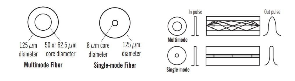
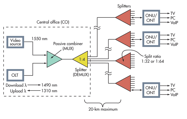
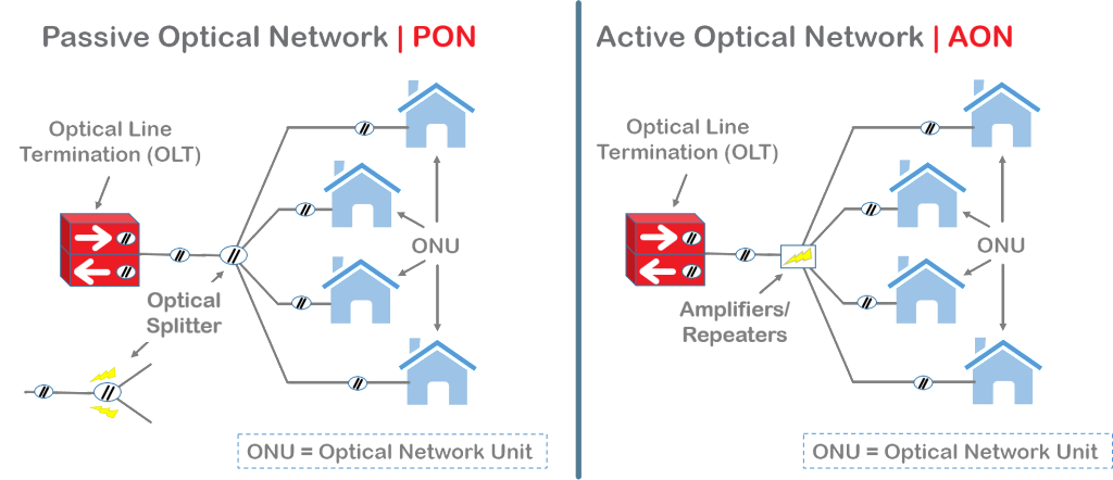
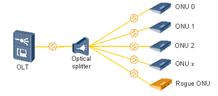
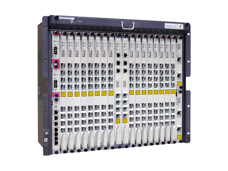
OLT: The optical line terminal is the main element of the network and it is usually placed in the Local Exchange and it’s the engine that drives FTTH system. OLT has two float directions: one is upstream getting distributing different type of data and voice traffic from users, the other is downstream getting data, voice and video traffic from metro network or from a long-haul networkand sending it to all ONT modules on the optical distribution network (ODN). The picture on the left shows an OLT.

ONT
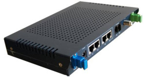
ONU/ONT: Optical network terminals or units are deployed at customer’s premises. ONTs are connected to the OLT by means of optical fiber and no active elements are present in the link. A single ONT can serve as point of access for one or multiple customers and be deployed either at customer’s premises or on the street in a cabinet. The ONU usually communicates with an ONT, which may be a separate box that connects the PON to TV sets, telephones, computers, or a wireless router. The ONU or ONT can be the same device. The picture on the right shows an ONT.

PON Splitter: Passive optical splitters divide a single optical signal into multiple equal but lower-power signals, and distribute the signals to users. The final splitting ratio can be achieved using a single splitter device.

PON Transceiver: PON transceiver is generally a bi-directional device that uses different wavelengths to transmit and receive signals between the OLT at the CO and the ONUs at the end users’ premises over a single fiber. PON transceiver can be divided into OLT transceiver module and ONU transceiver module. OLT transceiver is typically more complex than ONU transceiver.

PON splitter & transceiver

PONs offer low cost connectivity for a large number of users with high security and relatively low management needs. Telecommunications companies use PONs to provide triple-play services including TV, VoIP phone, and Internet service to subscribers. A PON could also serve as a trunk between a larger system, such as a CATV system, and a neighborhood, building, or home Ethernet network on coaxial cable. As PONs grows into millions of homes, it can be seen that a new era of access networks is upon us. Fiberstore offers a series of high reliability and affordable fiber optical access devices for PONs, including OLT, ONU/ONT, PON splitters and transceivers, to meet customers’ fast growing demand of PON deployment.

Introduction to Mode Conditioning Patch Cable

Mode conditioning patch cord (MCP) was developed as a solution for network applications where Gigabit Ethernet hubs with laser based transmitters are deployed. It is a special fiber optic patch cord and allows customer upgrading their hardware technology without the cost of upgrading fiber plant. In addition, MCP significantly improves data signal quality while increasing the transmission distance. The text will give some detailed information about mode conditioning patch cable.

What Is Mode Conditioning Patch Cable?

A mode conditioning patch cord is a duplex multi-mode patch cord that has a small length of single mode fiber at the start of the transmission leg, and also a single mode to multi-mode offset fiber connection part in this leg. There are two multi-mode fibers on one end and one multi-mode and one single mode fiber on the other end. It is fully compliant with IEEE 802.3z application standards. Mode conditioning patch cord causes the single mode transceiver to create a launch similar to a typical multi-mode launch. It is designed for long wavelength Gigabit Ethernet applications. The following picture shows the construction of a mode conditioning patch cable.

mode conditioning patch cord

How Does Mode Conditioning Patch Cable Work?

The basic principle behind the cord is that you launch your laser into the small section of single mode fiber. The launch of the light coming out of the equipment begins on a single mode fiber. The other end of the single mode fiber is coupled to multi-mode section of the cable with the core offset from the center of the multi-mode fiber. The light is launched on to the multi-mode fiber at a precise angle, giving the cable its mode conditioning properties. When we use such mode conditioning fiber optic patch cords, we need to connect the yellow leg which is the color of single mode to connect the transmit side of the equipment (single mode Gigabit transceiver) while we connect the orange leg which is the color of multi-mode to the receive side. The picture below shows how the single mode fiber is coupled to multi-mode section of the cable.

Mode Conditioning Fiber Patch Cable

How to Install Mode Conditioning Patch Cable?

To install a mode conditioning patch cable, you need to follow these steps:

  • Step1: Connect the yellow leg (single mode connector) of the MCP cable into the transmit bore of the transceiver.
  • Step2: Connect the rest orange legs (multi-mode connectors) of the MCP cable into the receive bore of the transceiver.
  • Step3: At the other end of the patch cord, put all the orange legs (multi-mode connectors) into the patch panel.
  • Step4: Repeat the above three steps for the second transceiver located at the other end of the network link.

After you have finished all the connection steps above, all the swap of transmit and receiver can only be done at the cable plant side.

Why Do We Need Mode Conditioning Patch Cable?

Transceiver modules used in Gigabit Ethernet (1000 Base-LX) launch only single mode (1300nm) long wave signals, which poses a problem if an existing fiber network utilizes multi-mode cable. When a single mode signal is launched into a multi-mode fiber a phenomenon known as differential mode delay (DMD) can create multiple signals within the multi-mode fiber. This effect can confuse the receiver and produce errors. By allowing the single mode laser launch to be offset away from the center of the multi-mode fiber, mode conditioning patch cord reduces the effect of such differential mode delay and provides a much higher operational bandwidth by precisely aligning a single mode termination at the laser transmitter. This is essential for networks using 62.5/125 and 50/125 multi-mode optical fiber and may be specified for current multi-mode networks depending upon the system requirements.

Mode conditioning patch cables are with various options, from all types of connectors to different jackets and different lengths. A variety of fiber optic connectors are available for your convenience, including: LC/UPC, SC/UPC, FC/UPC, ST/UPC, LC/APC, SC/APC, FC/APC, and MTRJ. Mode conditioning patch cables are built in the form of a simple duplex patch cable, so they can easily be installed in a system without the need for additional components or hardware. Their length can range from one meter and up to support virtually any network topography.

Visual Fault Locator Overview

Whether install new fiber links or troubleshooting an existing network, the faster you can locate a problem, the faster you can fix it. To locate the faults in fiber optic cables in a short time, various fiber optic testers are being invited to locate the faults of the fiber optic cable, like OTDR (optical time-domain reflectometer). However, OTDR has dead zone during the testing. Another simple and useful tester which can work in an OTDR dead zone is usually being used to work as an accessory of OTDR. It is known as VFL (visual fault locator) which can also work alone to locate the faults in fiber optic cable in a time saving manner in some situations.

What Is VFL?

Visual fault locator is now one of the most commonly used fiber optic testing devices to trace optical fibers, check fiber continuity and find faults such as breaks, bad splices and tight, sharp bends in fiber optic cable. The most popular visual fault locators are pen shape VFL and hand-held VFL, which are showed in the following picture respectively.

pen shape VFL and hand-held VFL

How VFL Works

The light used for transmit signals over fiber optic is usually at 1300 to 1650nm wavelength which is invisible to naked eyes. Unlike OTDR which measures the time of the incidence and the amplitude of the reflected pulses sent to the fiber optic cable to locate the faults, VFL uses powerful visible light at the 360 to 670nm wavelength injecting to a fiber to visually and directly locate the faults in fiber optic cable. The visible light travels along the core until it reaches a fault, where it leaks out. Light leaking through the fault can be seen through plastic coating and jackets under suitable illumination. This is how VFL locates the faults in fiber optic cable.

Visual fault locators radiate in continuous wave (CW) or pulse modes. The glint of the light source in VFL is usually at 1 or 2 Hz, kHz range is also being provided in today’s market. The output power is generally at 1 mW or less. The working distance of a VFL is usually in the range of 2 to 5 km.

How to Use VFL

VFL is very easy to use. The steps to use a VFL are provided as following:

  • Step One: remove the plastic connector covers from both ends of the test fiber cable.
  • Step Two: connect the fiber optic visual fault locator one end of the fiber. Press the tester button and observe that light emanates from the other end of the fiber. This gives a simple indication of the continuity of the fiber link.
  • Step Three: repeat with several other fibers. Check for light that can be seen leaking from a faulty splice. This may illustrate an easy way of carrying out visual fault finding on bad splices or joints.
  • Step Four: disconnect all equipment, put the plastic covers back on the connector ends and return everything to the state it was in before you started the practical so that the next group can carry out the practical in full.

VFL

Notes during the using of a VFL:

  • 1.Never look directly into the VFL’s output.
  • 2.Cover the VFL’s output with the dust cap when the VFL is not in use.
  • 3.Not recommended for use on dark colored or armored cables.

Using simple but useful technical principle, visual fault locator individually can provide an economic and time saving solution to locator faults in fiber optic cables in some cases. While working as an accessory of OTDR, VFL, together with OTDR, can provide the fiber technician the best solution to locate fiber faults.