Ethernet Cable vs Network Cable: What’s the Difference?

With the ever-increasing popularization of network applications in our daily life, people frequently hear words like “Ethernet cable” and “network cable”. We can easily get confused by these terms and questions like Ethernet cable vs network cable: What’s the difference? Whoever you are as long as you are network users, you need the basic knowledge to figure one from the other.

What Is Ethernet Cable?

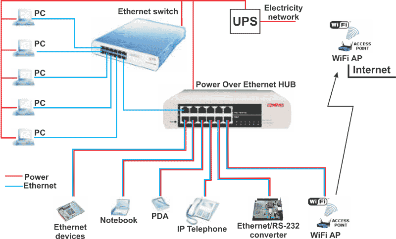
Ethernet cable is a concept of cabling network wire that specified to be used in LAN (local area network), MAN (metropolitan area network) and WAN (wide area network). In actual application, cables that installed in Ethernet to connect with devices like switches, routers and PCs and used as a common network medium for data transmission and power supply (Power over Ethernet, PoE) are called Ethernet cables. They are of great concern while setting up wired networks, for both bad cabling and low-quality cable leading to low network performance.

Ethernet cable

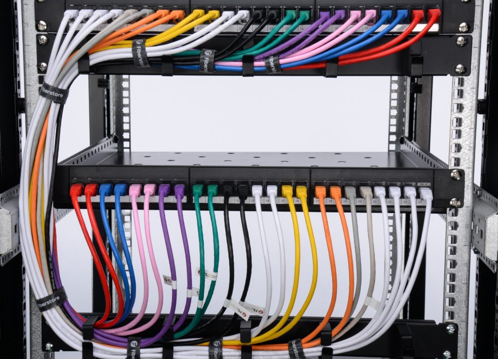
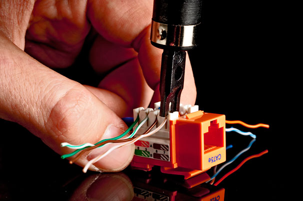
Figure 1: This photo shows the installation of Ethernet cable in the network center.

What Is Network Cable?

Network cable is a wide concept of all types of cables used in various network. It is used to connect and transmit data between a network and computers. There are a variety of network cables in the market, and different network cables are required for different network conditions. Ethernet crossover, twisted pair, coaxial and fiber optic are four of the most frequently used network cables.

Ethernet Cable vs Network Cable: What’s the Difference?

·Range Involved

Ethernet cable is a branch of network cable. Only network cables that used in Ethernet environments (LAN, MAN, WAN) are called Ethernet cable. Ethernet cable usually exclusively refers to a copper or aluminium cable. However, network cable refers to a large range of cable types such as patch cable and glass optical fiber. In fact, any cables that applied to networks are network cables.

·Classification

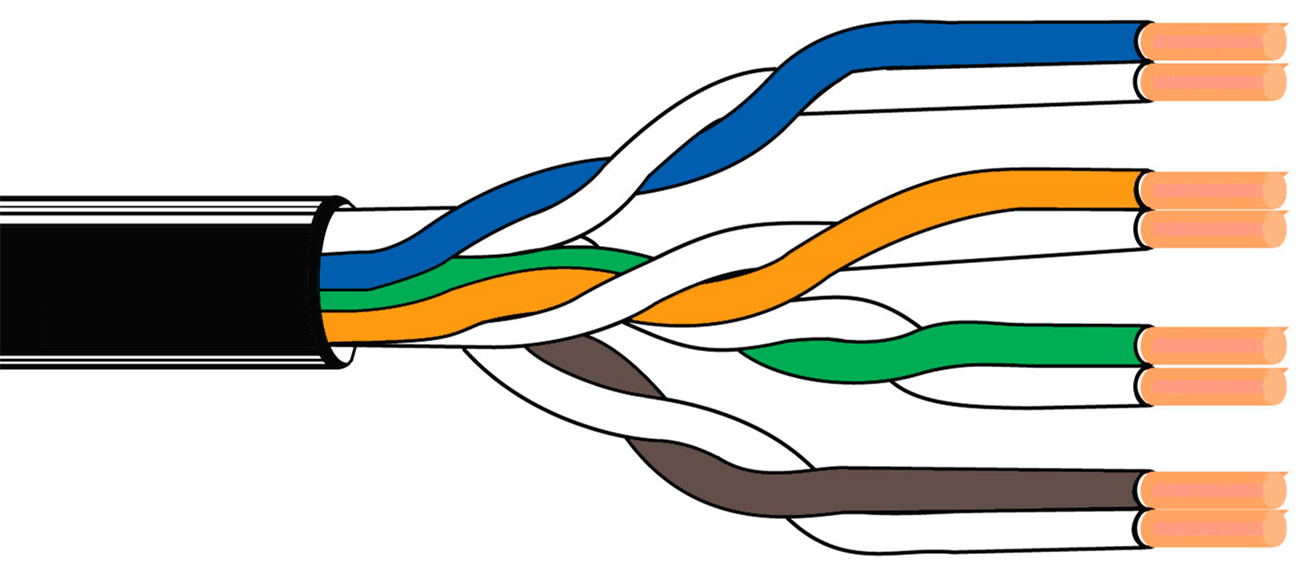
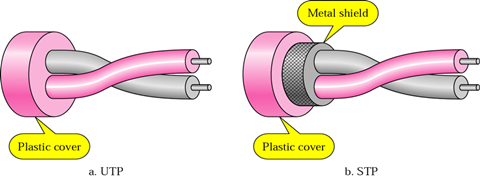
Modern Ethernet usually operates on twisted pair cables with 8P8C modular RJ45 connectors. An unshield one – UTP is the most identified type and thus be called as Ethernet cable. Ethernet cable is also commonly classified by standard categories. For example, Cat5e Ethernet cable and Cat6 cable are two most popular used Ethernet cables in the current market. Other updated Ethernet cables are Cat6a, Cat7a for higher performance. All the above specially mentioned as Ethernet cables are also network cables. However, modern technology has developed Ethernet, allowing it to run on coaxial and fiber optics cables, which is beyond the early Ethernet technology. This evolution makes the concept of Ethernet cable and network cable more close to each other.

Cat5e vs Cat6

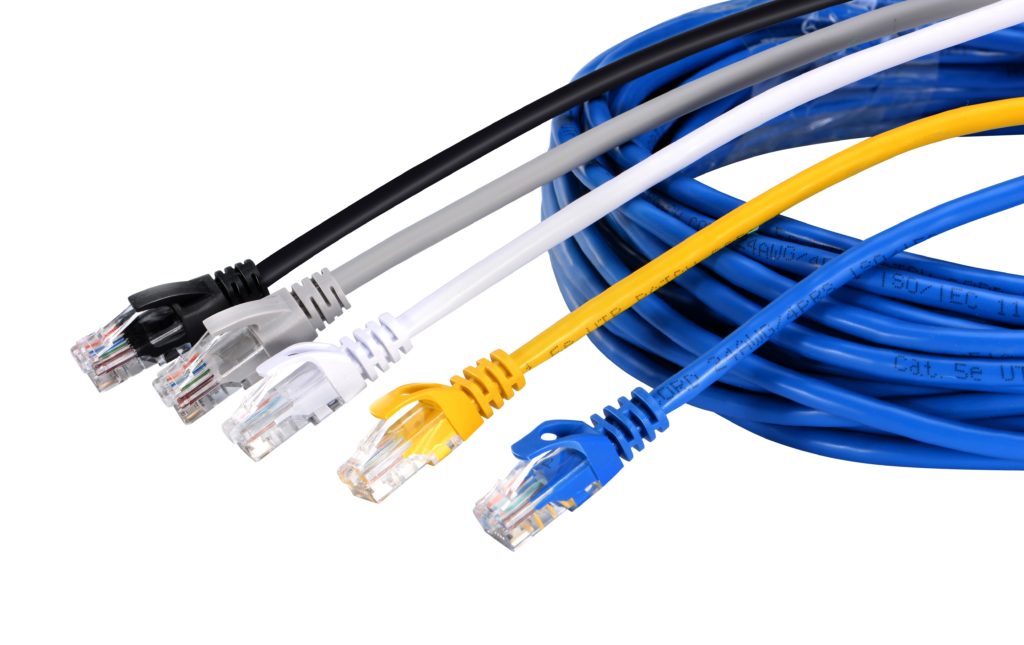
Figure 2: This photo shows the most popular used Cat5e and Cat6 cables.

·Application

Opposite to WLAN (WiFi, wireless local area network), Ethernet is a wired LAN access technology. Any cable attached to this access of network is called especially as “Ethernet cable” and generally as “network cable”. As for network, it defines both wired network and WLAN. As we know, WiFi has become more and more popular in the modern world. Will there be a special “wireless network cable” in the future to replace standard cable? Maybe change in structure and function is foreseeable, but the need for a wire to connect the server with a hub is always dispensable.

Conclusion

This article explained the concept of Ethernet cable vs network cable and made a contrast of them. Ethernet cable belongs to the category of network cable. Ethernet cable is exclusively pointed to an Ethernet environment, while network cable is a general concept of all cable types used in different network conditions.

Related Articles:
Running 10GBASE-T Over Cat6 vs Cat6a vs Cat7 Cabling?
Home Ethernet Wiring Guide: How to Get a Wired Home Network?
Patch Cable vs. Crossover Cable: What Is the Difference?
Ethernet Cable vs Patch Cable

10GBASE-T vs SFP+, Which is Preferred for 10G Network Cabling

As the basis of upgrading network, 10G network has been ubiquitous in data center, enterprise network and even home networking. 10GBASE-T and SFP+ transceiver are two different kinds of technology which transmit data via copper and fiber respectively. 10GBASE-T technology provides the most flexible and economical solution while 10G SFP+ offers the compatible and user-friendly solution for 10G Ethernet connectivity option. This article would shed light on 10GBASE-T vs SFP+.

10GBASE-T Technology

As the fourth generation of IEEE standardized Base-T technologies, 10GBASE-T is designed to reduce overall costs and improve flexibility. By using RJ45 connectors and unshielded twisted pair cabling, 10GBASE-T allows 10Mbps, 100Mbps, 1Gbps, and 10Gbps data transmission, while being backward-compatible with prior generations. Merits and demerits of using 10GBASE-T are listed in the below.

Pros of 10GBASE-T
  • Cheap twisted pair cables.
  • Patch panels can be used without messing around with transceivers.
Cons of 10GBASE-T
  • Higher power consumption.
  • People may get tempted to use substandard cabling, and this would have a negative influence on the speed.
  • No good way to extend length beyond 100m (though this can be somewhat mitigated by choosing switches with mostly 10GBASE-T but also a handful of SFP+ ports) limited choice of equipment.

10G SFP+ Technology

The 10G SFP+ transceiver meets the standard of Multi-Sourcing Agreement (MSA), and provides the cost effective solution for 10G optical data communication. It supports both duplex and simplex LC optics interfaces. The 10G SFP+ transceiver consists of 10Gbit/s DFB/EML optical transmitter and PIN receiver, which allow 300m~120km 10G Ethernet and 10G fiber channel applications. Advantages and disadvantages of using 10G SFP+ transceivers are listed in the below.

Pros of SFP+
  • Lower latency
  • Lower power consumption
  • Cheaper NICs and switches
  • More choice of connected equipment.
  • With transceivers and fiber basically any run length can be covered.
Cons of SFP+
  • Apparently, it is not a big deal for transmission within short distance.
  • For longer runs or runs that need to go through patch panels needs transceivers and optical fiber. Fiber itself is cheap but transceivers, termination, patch panels, and etc for fiber would cost a lot.

10GBASE-T vs SFP+

This passage would mainly demonstrate the difference between 10GbE base T and SFP+ options from the respective of technology, latency, and power consumption.

10GBASE-T vs SFP+: Technology

Generally, 10GBase-T is cheaper and easier to deploy than the alternative SFP+ technologies. You can further compare these two different technologies in the following table:

10GBASE-T vs SFP+ Comparison

10GBASE-T vs SFP+: Latency

Low latency is paramount to ensure fast response time and reduce CPU idle cycles. That increases data center efficiency and ROI. With the increasing of using private cloud applications, the need for low latency is growing fast in large scale data centers.

When it comes to 10GBase-T, the PHY standard uses block encoding to transport data across the cable without errors. The standard specifies 2.6 microseconds for the transmit-receive pair, and the size of the block requires that latency to be less that 2 microseconds. SFP+ uses simplified electronics without encoding, and typical latency is around 300 nanoseconds (ns) per link. You can further compare them in the below table.

10GBASE-T vs SFP+ latency comparison

Basically, there are only slight differences between 10GBASE-T and SFP+ in terms of application latency. Relatively speaking, 10G SFP+ has lower latency than 10GBASE-T. High latency would exert negative influence on CPU and therefore limiting data center efficiency and increasing operational costs.

10GBASE-T vs SFP+: Power Consumption

10GBase-T components today require anywhere from 2 to 5 watts per port at each end of the cable (depending on the distance of the cable) while SFP+ requires approximately 0.7 watt (regardless of distance). The difference is clearly shown in the below chart.

10GBASE-T vs SFP+ power consumption comparison

(Resource: http://www.datacenterknowledge.com)

10GBASE-T vs SFP+, Which Will You Choose

Through this article, we are clear about the pros and cons of 10GBASE-T and SFP+ as well as their differences in technology, application latency and power consumption. It is evident that SFP+ is the right technology to ensure optimal performance with lowest latency and lower power usage in the data center. The cost saving becomes obvious when deploying from 1000 to 10,000 cables in the data center.

Related Articles:

XFP vs SFP+, What’s the Difference? Can We Connect XFP and SFP+?

Understanding of 10GBASE-T SFP+ Copper Transceiver Modules

Choose 10GBASE-T Copper Over SFP+ for 10G Ethernet

Punch Down Tools User Guide

The term “punch down” is used for the physical force needed to pierce or take away the cable insulation while the connection is being made. Punch down tools or krone tools (named after the Krone LSA-Plus connector) are widely used for copper network built by Ethernet cables including cat 5, cat 5e, cat 6, etc. As we know, these copper cables can be connected with keystone jacks, cross-connect blocks, patch panels and surface mount boxes. Therefore, the function of punch down tools is to insert the wires into the IDC (insulation-displacement connectors) on these terminations. This post is going to introduce some basic knowledge about punch down tools and the proper way to use them.

punch-down-tools

Operation Principle of Punch Down Tools

Many punch down tools are composed of a handle, an internal spring mechanism and a removable slotted blade. After positioning the wire into a slotted post on a punch down tool, just pressing down the tool on top of the wire over the post. Then the internal spring will be triggered by the required pressure and the blade pushes the wire into the slot. At the same time, the blade cuts the insulation and secures the wire.

punch-down-process

Instructions for Using Punch Down Tools

Step one, make preparations before punching down a wire. When gripping the punch down tool in one hand, you should ensure that the cutting blade is facing down. Then coil the wire through the connection block terminal by another hand.

Step two, punch down the wire. You should firmly hold the wire’s end in hand and set the tool’s blade on the selected connection terminal. Then pressing the tool forward with a straight move until reaching the bottom of terminal. If you are doing it right, any excess wire would be cleanly cut off and the remaining wire would be easily connected to the terminal.

Step three, check the wire connection. Make sure the connection is secure and no broken or loose wire is left in the connection block. You can test to see if the wire is indeed fastened securely to the right terminal by tugging on it.

Helpful Tips

Tip one, always wear safety goggles or glasses when using the punch down tools. Because small pieces of wire will fly in all directions during the punch down process, which is a potential risk to your eyes.

Tip two, if the wire slips out of the connection block, you can use a flat head screwdriver to slightly increase the pressure applied by the punch down tool.

Tip three, if using the highest pressure setting, the tool still cannot cut through the cable. Then the cutting edge must become dull. This means that you need to replace the blade with a new one.

Tip four, do not use a punch down tool to tighten up flat head screws as this can break or shatter the blade.

Tip five, though most models are made of plastic, punch down tools can still conduct current. Keep this in mind when working with electrical circuits.

Tip six, you should always carry at least one extra blade for each type of termination that you are doing. Blades don’t break often, but they do break occasionally.

Tip seven, a 4” square of carpet padding or mouse pad makes a good palm protector when punching down cable on modular jacks.

Conclusion

Punch down tools are usually applied to data or telecom network wiring in computers, phones and audio devices. Of course, many types of punch down tools are available to meet different requirements. Good tools even have replaceable blades. Employing punch down tools greatly accelerates the working efficiency and reduces the task difficulty. It is important for technicians to use them in daily applications.

Getting to Know PoE Network

With the rapid development of networking, a variety of technologies have been created. In 2003, PoE (power over Ethernet) network technology has been standardized. And it is now widely used for wireless LANs (local area networks), IP cameras and VoIP (voice over Internet protocol) phones. PoE allows cables to carry both electrical power and data signal to devices. Electrical current will support the operation of devices which greatly reduces the amount of wires used for network installation. Thus, the emergence of PoE network is absolutely a good news for the development of cost-efficient networking. Next, more information about PoE network will be discussed in the following paragraphs.

PoE-network

Operating Principle of PoE

There are three basic components in PoE system – PSE, PD and Ethernet cable. PSE (power sourcing equipment) like PoE switch is the device used for delivering power to cable. PD (powered device) is the device used for receiving power from the cable. And cable will help transmit the electrical power and data signal. The electrical current will first go into the cable at the PSE end, and then come out at the PD end. Since it is the transmission of electric signal, PoE is only available to twisted pair Ethernet cabling. Also, the current is separated from data signal so that neither of them interferes with the other.

Advantages of PoE

Using the PoE network has many advantages:

  • Flexibility
    Because devices like IP cameras and wireless access points are not permanently attached to an electrical outlet, they can be located regardless of area restriction. Reinstallation is also easy to implement.
  • Safety
    PoE network is designed to be safe enough to protect network equipment from overload, underpowering, or incorrect installation.
  • Dependability
    PoE power comes from a central and universally compatible source instead of a collection of distributed wall adapters. And an uninterruptible power supply is backing up the PoE network for a more stable operation.
  • Scalability
    Owing to the electrical power available on PoE network, the installation and distribution of network connections are more simple and effective.
Applications of PoE

VoIP phones, WLAN, RFID (radio frequency identification), security cameras or access control devices are major applications for PoE network. Using PoE network enables the VoIP to receive uninterrupted power through the network, without the need for an AC outlet for each phone. And WLAN access point can be placed in different locations such as ceilings, hallways, lobbies without electrical outlets. Likewise, PoE allows RFID readers to be strategically situated in locations that optimize effectiveness. And it is cheaper to use PoE network for security cameras or access control devices on ceilings, hallways, lobbies, or outdoor areas.

Conclusions

To sum up, the advent of PoE has greatly improved the effectiveness of network. Equipment are able to be located at any place due to the power availability. And a large number of cost will be saved by eliminating unnecessary wires. This article only gives a brief introduction to the PoE network. There still has a lot for us to explore.

Related Article: Introduction to PoE Networking Architectures

Categories of Twisted Pair Introduction

As one of the oldest types of cable ever invented, twisted pair cabling was first developed by Alexander Graham Bell in 1881. Since then, it has been widely deployed for telephone line network in America. Nowadays, their are various categories of twisted pair cables have been extended worldwide mainly for outdoor land lines offering telephone voice service.

Generally speaking, twisted pair cabling is a kind of copper wiring that two conductors of a single circuit are twisted together. The purpose of using twisted pair is to offset electromagnetic interference (EMI) from external sources to stop degrading the performance of circuit. Also, different standards of twisted pair are specified into various categories as cat 1, cat 2, cat 3, cat 4, cat 5/5e, cat 6/6a, cat 7/7a, cat 8/8.1/8.2. And this article will give a brief introduction to some common categories of twisted pair cables.

categories of twisted pair cables

Different Categories of Twisted Pair
1) Cat 5/5e

Cat 5 twisted pair cable is often used for structured cabling of computer networks. It is available to 10/100 Mbps speeds at up to 100 MHz bandwidth. However, it is now considered to be obsolete and replaced by cat 5e (enhanced). Cat5e cable is one the most commonly used twisted pair cables at present. The biggest distinction between cat 5 and cat 5e is that cat 5e has a lower cross talk and its transmitting speed can reach up to 1000 Mbps.

2) Cat 6/6a

As a substitute of cat 5/5e, cat 6 twisted pair is applied to Gigabit Ethernet and other network physical layers. It supports up to 10 Gbps speed at 250 MHz. When used for 10GBASE-T applications, Cat6 cable has a reduced maximum length from 37 to 55 meters. But cat 6a (augmented) has been evolved to perform at up to 500 MHz, thus the maximum cable distance is longer than cat 6 of up to 100 meters.

3) Cat 7/7a

Cat 7 is the standard for twisted pair cabling used for 1000BASE-T and 10GBASE-T networks. It provides performance of up to 600 MHz with a maximum length of 100 meters. As for the cat 7a (augmented) cable, it has a higher frequency of 1000 MHz. Results show that it may be possible to support 40 GbE or even 100 GbE at a very short length.

4) Cat 8/8.1/8.2

Cat 8 is the USA standard specified by ANSI/TIA while cat 8.1 and cat 8.2 are specified by ISO/IEC for global application. All these three kinds of cat 8 twisted pairs are used for 25GBASE-T and 40GBSE-T at the maximum frequency of up to 2 GHz. Except cat 8 adopts cat 8 links, cat 8.1 uses class I links and cat 8.2 uses class II links. The key difference between class I and class II is that class II allows three different styles of connectors to be not compatible with one another, or with the RJ45 connector.

Conclusion

Twisted pair cables have been classified into different grades called categories. These standards especially formulate the data capacity of the cable. Higher categories are more expensive than lower ones, but most of cost is actually spent on labor force for installing the cables. And twisted pair cables under cat 5 are not recommended now. Higher categories are the future trends for network cabling.

A Copper-based Gigabit Ethernet Solution – 1000BASE-T

Enormous efforts put on the development of high-performance Ethernet technology that provides gigabit-per-second transmission rates have led to the extension of Gigabit products to include the copper Gigabit Ethernet (GbE) standard: 1000BASE-T. Many papers and articles have been attributed to introducing the fiber-optic GbE standards, such as 1000BASE-SX, 1000BASE-LX, 1000BASE-ZX. And contributions are few about 1000BASE-T. This text just helps you to better understand 1000BASE-T and talks about it: a copper GbE solution.

What Is 1000BASE-T Technology?

1000BASE-T is also known as IEEE 802.3ab. Just judging from its name, “1000” here means the transmission speed of 1000Mbps. The “BASE” refers to BASE band signaling, indicating that only Ethernet signals are carried on the medium. The “T” represents twisted-pair copper cable (for example Cat 5). More specifically, 1000BASE-T uses four pairs of Cat 5 unshielded twisted pair (UTP) to achieve the Gigabit data rate and achieves 1000Mbps data rates by sending and receiving a 250Mbps data stream over each of the four pairs simultaneously. The distribution of four-pair Cat 5 cabling extends from the work area to the equipment room and between equipment in the equipment room, thus enabling connectivity to switched and shared gigabit services for both high-bandwidth work area computing and server farms.

four cat 5 UTP pairs

1000BASE-T is able to provide half-duplex (CSMA/CD) and full-duplex 1000Mb/s Ethernet service over Cat 5 links as defined by ANSI/TIA/EIA-568-A. Besides GbE applications over Cat 5 copper cabling, 1000BASE-T also supports other specifications. First, it supports the Ethernet MAC (Media Access Control), and is backward compatible with a 10/100 Mbps Ethernet. Second, many 1000BASE-T products support 100/1000 auto-negotiation, and therefore 1000BASE-T can be incrementally deployed in a Fast Ethernet network. Third, 1000BASE-T is a high-performing technology with less than one erroneous bit in 10 billion transmitted bits. (10 is the same error rate as that of 100BASE-T.) Topology rules for 1000BASE-T are the same as those used for 100BASE-T.

Why Choose This Copper Gigabit Ethernet Solution?

Why network designers choose 1000BASE-T as the copper GbE solutions? Or put it in another way, what are the advantages of 1000BASE-T?

  • Performance—1000BASE-T scales Ethernet 10/100Mbps performance to 1000Mbps. Compared with 1Gbps, 1000BASE-T is 100 times as fast as the standard Ethernet. It permits the smooth migration of the 10/100 networks to 1000 Mbps-based networks. When 1000BASE-T technology is deployed in transceiver modules, these 1000BASE-T copper SFP transceivers, such as Fiberstore compatible Cisco SFP-GE-T, make shared gigabit service possible and aggregate one gigabit of server support. This Cisco 1000BASE-T SFP supports 1000BASE-T operation in host systems with a compact RJ-45 connector assembly.

SFP-GE-T, Cisco 1000BASE-T SFP

  • Cost—Used in conjunction with Full Duplex Repeaters (FDRs), 1000BASE-T can provide highly cost-effective shared gigabit service. FDRs offer the traditional low-cost shared media operation of repeaters, but when coupled with 1000BASE-T, they offer an easy-to-manage, high-burst rate, shared-media solution capable of supporting both end users and server farms. In such a case, to aggregate one gigabit of server support is possible in a cost-effective way.
Notes on Using 1000BASE-T Products

While realizing a 1000Mb/s data stream over four pairs of Category 5 twisted pair cables meet several challenges may meet several challenges, like signal attenuation, echo, return loss, etc.

  • Attenuation is the signal loss of the cabling from the transmitter to the receiver. Attenuation increases with frequency, so designers are challenged to use the lowest possible frequency range that is consistent with the required data rate.
  • Echo is a by-product of dual-duplex operation, where both the transmit and receive signal occupy the same wire pair. The residual transmitted signal because of the trans-hybrid loss combines with the cabling return loss to produce an unwanted signal referred to here as echo.
  • Return loss is a measure of the amount of power reflected due to cabling impedance mismatches.
Conclusion

1000BASE-T technology is the ideal high-speed solution for these application when 1000BASE-T uplinks from desktop switches to aggregating switches. Many network designers have chosen this copper GbE solution for high network performance in a cost-effective way. Fiberstore supplies many 1000BASE-T SFPs which are fully compatible with major brands, like Cisco GLC-T and SFP-GE-T mentioned above. For more information about 1000BASE-T SFPs, you can visit Fiberstore.

Related Article: A Quick Overview of Cisco 1000BASE-T GLC-T SFP Copper Module

Guide to Coaxial Cable, Twisted Pair Cable and Fiber Optic Cable

The advancements of cable-based technologies have made wider accessibility to greater bandwidth possible in Local Area Network (LAN). With so many network options, to select a right cable-based solution for broadband connection services is a little confusing. When such factors as cost, speed, bandwidth and immunity are considered, which one is an ideal choice for networks, coaxial cable or twisted pair cable? Or is the fiber optic cable that meets your needs?

Coaxial Cable

Coaxial cable, or  in a foam insulation, symmetrically surrounded by a woven braided metal shield, then covered in a plastic jacket. Because of its insulating property, coaxial cable can carry analogy signals with a wide range of frequencies. Thus it is widely used in feedlines connecting radio transmitters and receivers with their antennas, computer network connections, digital audio, and distributing cable television signals. The following figure shows the structure of coaxial cable.

Coaxial cable, a single wire usually copper wrapped

Actually, there exists another cable, twin-ax cable, which is similar to coaxial cable, but with two inner conductors instead of one. This kind of cable comes in either an active or passive twin-ax (twin-axial) cable assembly, used for 10, 40 or 100 Gigabit Ethernet (GbE) links.Like QSFP-H40G-CU1M, this Cisco 40G cabling product is the QSFP to QSFP passive copper cable assembly designed for high-performance 40GbE networks.

QSFP-H40G-CU1M, QSFP to QSFP passive copper cable assembly

Twisted Pair Cable

Twisted pair cable is a type of wiring in which two conductors of a single circuit are twisted together. It comes in two versions: Shielded Twisted Pair (STP) and Unshielded Twisted Pair (UTP). STP is commonly used in Token Ring networks and UTP is in Ethernet networks. The image below displays what UTP (left) and STP (right) look like.

Twisted pair cable, UTP and STP

Fiber Optic Cable

A fiber optic cable is a cable containing one or more optical fibers. Fiber optic cables often contain several silica cores, and each fiber can accommodate many wavelengths (or channels), allowing fiber to accommodate ever-increasing data capacity requirements. When terminated with LC/SC/ST/FC/MTRJ/MU/SMA connectors on both ends, such as LC-LC, LC-SC, LC-ST, SC-ST, SC-SC, ST-ST etc, fiber optic cables can achieve fiber link connection between equipment.

Comparison of Three Kinds of Cables

Coaxial cable can be installed easily, relatively resistant to interference. However, it is bulky and just ideal for short length because of its high attenuation. It would be expensive over long-distance data transmission. By contrast, twisted pair cable is the most flexible and cheapest among three kinds of cables, easy to install and operate. But it also encounters attenuation problem and offers relatively low bandwidth. In addition, it is susceptible to interference and noises. As one of the most popular mediums for both new cabling installations and upgrades, including backbone, horizontal, and even desktop applications, fiber optic cable is small in size and light in weight. Because the conductor is glass which means that no electricity can flow through, fiber cable is immune to electromagnetic interference. The biggest advantage of fiber optic cable is that it can transmit a big amount of data with low loss at high speed over long distance. Nevertheless, it needs complicated installing skills, difficult to work with and expensive in the short run.

When selecting which kind of cable is appropriate for network services, one should keep in mind that each cable has its unique advantages and disadvantages concerning about these factors: cost, speed, security, reliability, bandwidth, data carrying-capacity, and so on.

Conclusion

Choosing among coaxial cable, twin-ax cable, twisted pair cable and fiber optic cable depends on your needs. You can balance the cost and the requirements of bandwidth to make a choice. In Fiberstore, you can find twisted pair cables and a series of fiber optic cables. Other cables, such as active optical cable (AOC) (eg. QSFP-4X10G-AOC10M) are also available for your networks. You can visit Fiberstore for more information about cable-based solutions.