Nowadays, many data centers are migrating into the 40G and 100G transmission. To prepare for this change, MPO/MTP technology is applied to meet the requirements of high density patching. Typically, a fiber optic link needs two fibers for full duplex communications. Thus the equipment on the link should be connected properly at each end. However, high density connectivity usually requires more than two fibers in a link, which makes it more complex to maintain the correct polarity across a fiber network, especially when using multi-fiber MPO/MTP components for high data rate transmission. Therefore, many technicians would prefer to use pre-terminated MPO/MTP components designed with polarity maintenance for easier installation. This article will specifically guide you to understand the polarity of MPO/MTP products and the common polarization connectivity solutions.
Keeping the right polarity is essential to the network. A transmit signal from any type of active equipment will be directed to the receive port of a second piece of active equipment and vice versa. Polarity is the term used in the TIA-568 standard to explain how to make sure each transmitter is correctly connected to a receiver on the other end of a multi-fiber cable. Once the component is connected to the wrong polarity, the transmission process will be unable to go on.
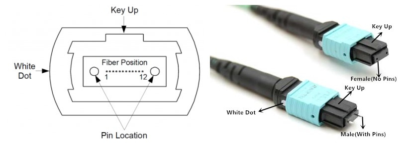
When discussing about the polarity, MPO/MTP connector is an important component for you to know. An MPO/MTP connector has a key on one side of the connector body. There are two positions of the key – key up or key down. Key up position means that the key sits on top. When the key sits on the bottom, it is the key down position. Moreover, the fiber holes in the connector are numbered in sequence from left to right named as P1 (position 1), P2, etc. Each connector is additionally marked with a white dot on the connector body to designate the P1 side of the connector when it is plugged in. The MPO/MTP connector can be further divided into female connector and male connector. The former has no pins while the latter has two pins on the connector. The following picture shows the basic structure of MPO/MTP connector.

The TIA standard defines two types of duplex fiber patch cables terminated with LC or SC connectors to complete an end-to-end fiber duplex connection: A-to-A type patch cable is a cross version and A-to-B type patch cable is a straight-through version. Based on this, there are three polarity connecting methods for MPO/MTP products. Here will introduce them in details.

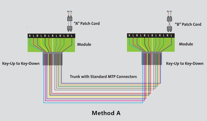
Method A is the most straight-forward method. It uses straight-through patch cords (A-to-B) on one end that connect through a cassette (LC-to-MPO or SC-to-MPO depends on what the equipment connector is), a straight-through MPO/MTP key up to key down backbone cable and a “cross-over” patch cord (A-to-A) at the other end.

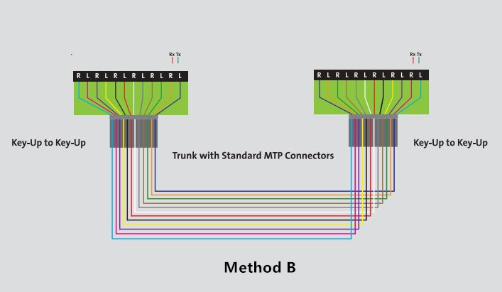
Method B is the “cross-over” occurred in the cassette. The keys on the MPO cable connectors are in an up position at both ends, but the fiber that is at connector P1 in one end is in P12 at the opposite end, and the fiber that is in P12 at the originating end is in P1 at the opposing end. Only A-to-B type patch cord is needed for this method.

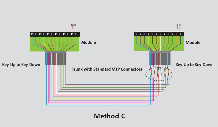
Method C is the most complicated. There is pair-wise “cross-over” in the backbone cable. A-to-B patch cords are used on both ends. The cassette uses MPO/MTP key up to key down and the backbone cable is pair-wise flipped so P1, P2 connects to P2, P1 and P3, P4 connects to P4, P3, etc.

Knowing the polarity of MPO/MTP system helps you better upgrade the 40G and 100G networks. According to different polarity methods, choosing the right MPO/MTP patch cables , connectors and cassettes will provide greater flexibility and reliability for your high density network.
