LC Connector Introduction

Fiber optic connectors are used to the mechanical and optical means for cross connecting fibers. Fiber optic connectors can also be used to join fiber cables to transmitters or receivers. There have been many types of connectors developed for fiber cable. Single mode networks have used FC or SC connectors in about the same proportion as ST and SC in multimode installations. But LC connector with smaller size and higher performance has become popular and the connector choice for optical transceivers for systems operating at gigabit speeds. The following text gives a detailed introduction of LC connector.

History of LC Connector

LC stands for Lucent Connector, as the LC connector was developed by Lucent Technologies as a response to the need by their primary customers, the telcos, for a small, low insertion loss connector. Then the LC design was standardized in EIA/TIA-604-10 and is offered by other manufacturers.

SC connector and LC connector

Advantages of LC Connector

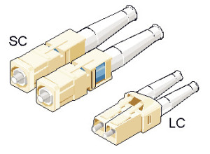
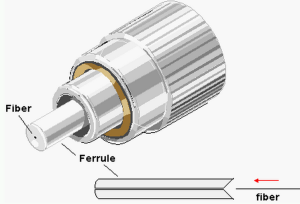
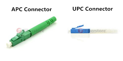
There are solid reasons that the LC is the preferred connector for high-performance network. From the appearance, LC connect is like a mini size of SC connector. LC connector borrows split-sleeve construction and a cylindrical ferrule (usually ceramic) from SC connector. LC connector has a push-and-latch design providing pull-proof stability in system rack mounts. The picture on the right shows the appearance of SC connector and LC connector.

The ferrule size of LC connector is 1.25 mm which is half the size of SC connector ferrule—2.5 mm. LC connector is rated for 500 mating cycles and its typical insertion loss is 0.25 dB. An interesting feature of the LC is that, in some designs, the ferrule can be “tuned” or rotated with a special tool after it has been assembled. This offers a considerable performance advantage. The design and performance of LC connector address the need for high density and low insertion loss.

Application of LC Connector

LC connector can be found in many places for termination and connection, especially SFP transceivers for gigabit transmission. For example, the optic interfaces of Cisco SFP transceivers are all LC connectors. Some other applications are as following:

Simplex and duplex LC connectors

  • Telecommunication networks
  • Local area networks
  • Data processing networks
  • Cable television
  • Fiber-to-the-home
  • Premises distribution
LC Connector Selection Guide

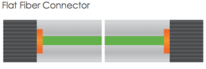
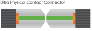
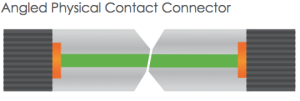
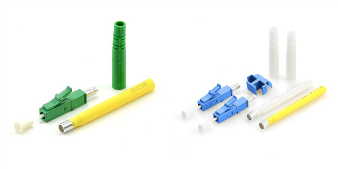
To meet the needs of market, there are various types of LC connectors provided now. During the selection of LC connector, transmission media should be the first factor to consider. LC connector favors single mode fiber optic cable. But it can also be used with multimode fiber optic cable. Signals sometimes are transferred over simplex fiber optic cable and sometime duplex fiber optic cable. Thus, LC connector has both simplex and duplex design. The picture above shows an APC simplex LC connector on the left and a UPC duplex LC connector on the right. Some other factors like polishing style (APC or UPC), hole size and cable diameter should not be ignored. For more details about LC connectors, you can visit Fiberstore which provides various LC connectors with high performance and low price.

Introduction of PC, UPC and APC Connector

When we choosing a LC connectors, you might hear descriptions like LC UPC polished fiber optic connector, or LC APC fiber optic connector. Or when you are choosing a ST fiber optic patch cable, you can find the description like ST/PC multimode fiber optic patch cable. What do PC, UPC, APC stand for? The following text will give the explanations.

fiber optic connector ferrule

PC (physical contact), UPC (ultra physical contact) and APC (angle physical contact) are the polish style of ferrules inside the fiber optic connectors. Unlike copper cables with copper wire in the connectors as connection media, fiber optic connectors are with ceramic ferrules for connection. The picture on the left shows the ferrule in fiber optic connector. Different fiber optic connectors has different ferrule size and length. Also their polish style might be different.

To better understand the why we have PC, UPC and APC, let’s start with the original fiber optic connector which has a flat-surface and is also known as flat connector (showed in the following picture). When two flat fiber connectors are mated, an air gap naturally forms between the two surfaces from small imperfections in the flat surfaces. The back reflection in flat connectors is about -14 dB or roughly 4%. To solve this problem, the PC connectors came into being.

flat fiber connector

In the PC connector, the two fibers meet, as they do with the flat connector, but the end faces are polished to be slightly curved or spherical. This eliminates the air gap and forces the fibers into contact. The back reflection is about -40 dB. The following picture shows two end faces of PC connectors.

PC connector

UPC connector, usually has a blue-colored body, is an improvement to the PC connector with a better surface finish (as showed in the following picture) by an extended polishing. The back reflection of UPC connector is about -55 dB which lower than that of a standard PC connector. UPC connectors are often used in digital, CATV and telephony systems.UPC connector

PC and UPC connectors have reliable, low insertion losses. However, their back reflection depends on the surface finish of the fiber. The better the fiber gain structure, the lower the back reflection. If the PC and UPC connectors are continually mated and remated, back reflection will degrade. An APC connector won’t have such problem. Its back reflection does not degrade with repeated matings.

APC connector

APC connector usually has a green body with an end-face still curved but are angled at an industry-standard 8 degrees (showed in the above picture) which allows for even tight connections and smaller end-face radii. Thus any light that is redirected back towards the source is actually reflected out into the fiber cladding, again by virtue of the 8 degree angled end-face. APC ferrules offer return losses of -65dB. Some applications that are more sensitive to return loss than others that call for APC connectors, like FTTx and Radio Frequency (RF) applications. APC connectors are also commonly used in passive optical applications due to the fact that many of these systems also use RF signals to deliver video.

APC connector and UPC connector

PC, UPC or APC, which should be the choice of fiber optic connector? The answer is it depends. Choosing the appropriate connector for a fiber network depends on things such as, network design and function. Fiberstore offers a wide range of fiber optic connector as well as professional optical network solution. For more information you can visit Fiberstore.

How to Choose the Fittest Network Face Plates?

Although FTTx is now being widely applied, many places are not able to use optical fiber or FTTx. For example, CAT6 or CAT5e cables are still occupying a certain proportion comparing with fiber optic cables. In some places FTTx and CAT5e/CAT6 network cables are being operated at the same time. In the mentioned situations, network face plates should be taken into consideration during cabling.

Network Face Plate is usually a plastic plate with one or more ports, which allows copper network cables to run between rooms beneath floors and behind walls. It is important to choose appropriate network face plates or wall plates during cabling.

Before you install network face plates, you should know which ones satisfy your needs most. The face plates you choose should conform to the standard you have chosen for your overall system. A good choice of network face plates or wall plates will not only help to maintain the quality of your infrastructure, but also save valuable spaces and cost. How to select the appropriate network face plates and wall plates? The following will give you the answer.

First, you should make sure how many types of cables you need to run. Usually, people need multiple medium to maintain communication. For example, telephone, Internet and TV are always the “must-have” medium during home network cabling. They should be connected with different network face plates. You might need several network face plates separately with RJ45 port, RJ11 port and TV port. However, in many situations, those cables come into home from one location. Then, it could be really bothering to install these face plates one by one. In addition, it’s not space saving and the appearance is not nice. Luckily, you can find that many manufacturers are providing network face plates with multiple ports in one to meet your specific networking needs. For example, except the network face plate with one port, Fiberstore also provides many other network face plates like the followings:

  • Face plate with one or more RJ45 port(s) and one or more TV port(s)
  • Face plate with a RJ45 port, RJ11 port and a TV port
  • Face plate with a RJ45 port, a RJ11 port, as well as an electrical socket and switch.

wall face plate with two RJ45 ports and two TV portsone RJ45 port, one RJ11 port, one electrical socket and one switch in a wall face plate

The above picture on the left shows a network face plate with two RJ45 ports and two TV ports. The above picture on the right shows a network face plate with one RJ45 port, one RJ11 port, one electrical socket and one switch.

Fiberstore could even provide RJ45 wall plate with a RJ45 port and a SC port for the situations in which both copper cable and fiber optic cable are being used.

RJ45-SC wall plate

The above picture shows a RJ45 wall jack with a RJ45 port and a SC port.

The size of the network face plate is another thing should be considered during cabling. There are generally 3 types of standard network face plates. They are known as 86 type, 118 type and 120 type network face plates. 86 type network face plate is square, with a size of 86*86mm, with one to three ports. 118 type network face plate is a rectangle network face plate generally with a 118*72mm size or other sizes. 120 type network face plate usually has a size of 120*120mm, 120*60mm or other accordingly.

One more thing cannot be ignored during network cabling is the cable type. The most commonly used copper network cables are CAT5e or CAT6. It is essential to make sure whether the network face plates are suitable for the cables you chose.

By taking the mentioned aspects into consideration, you are sure to find the right network face plates for your needs.

Fiberstore supplies a variety of network face plates, such as AMP Face Plate BS Shuttered, 86 type network face plates, 118 type network face plates. These face plates are available with 1 port, 2 ports, 4 ports, etc. Our high quality network face plates are compliant with international standards with low price and worldwide delivery. They can help you save time & money for your business or project.

Introduction of Fiber Optic Wall Plate

When talking about fiber optic cabling system, the related products that come to our mind firstly are usually fiber optic cables, fiber optic transceivers, connectors or fiber optic transmission products. However, there are still many other components whose importance should not be ignored. Fiber optic wall plate, or outlet, is one of these components, and is also one of the most visible components in a fiber optic cabling system. This text will introduce you this component and offer you the Fiberstore‘s fiber optic wall plate solution.

What is Fiber Optic Wall Plate?

Fiber optic wall plate is a flat plastic or metal plate that allows connection to fiber cable carrying optical signals. It serves as a transition point between the fiber optic cable and equipment. Fiber optic wall plates are usually mounted in or on walls, but some of them can also be mounted in floors and ceilings. Fiber optic wall plate includes one or more ports, and each port is available with an adapter.

Applications of Fiber Optic Wall Plate

Fiber optic wall plates are designed to bring fiber to the desk and widely used in multi-floor and high building. It can be found in:

  • FTTH access
  • Telecommunication
  • CATV
  • Data Communication Networks etc.
Types of Fiber Optic Wall Plate

Fiber optic wall plates come in many different types according to their adapter type, port number and faceplate interface.

According to the faceplate interface of the plates, there are bevel fiber optic wall plates and hybrid fiber optic wall plates.

Fiber optic wall plates can contain one or more adapters. The number of ports a plate can have is based on the size of the plate. Here listed some of the fiber optic wall plates:

  • Single port fiber optic wall plates
  • 2-port fiber optic wall plates
  • 3-port fiber optic wall plates
  • 4-port fiber optic wall plates
  • 6-port fiber optic wall plates
  • 8-port fiber optic wall plates
  • 12-port fiber optic wall plates

The following picture shows a single port ST fiber optic wall plate outlet.

wall plate

To satisfy different demands during cabling, sundry kinds of adapters could be installed on fiber optic wall plates. And these adapters could be the same ones or different. If classified by the adapters, the types of fiber optic wall plates will be various. Parts of the fiber optic wall plates classified by the adapters are listed as following:

  • FC fiber optic wall plates outlets
  • SC fiber optic wall plates outlets
  • ST fiber optic wall plates outlets
  • LC fiber optic wall plates outlets
  • SC-ST fiber optic wall plates outlets
  • RJ45-SC fiber optic wall plates outlets
  • SC-ST-LC fiber optic wall plates outlets
  • FC-SC-ST-LC fiber optic wall plates outlets

wall plate pic 2

The above picture shows a 2-port FC bevel fiber optic wall plate outlet. The picture below shows a 4-port SC/ST/FC/LC hybrid fiber optic wall plate outlet.

wall plate pic 3

Fiberstore’s Fiber Optic Wall Plate Solution

Fiberstore supplies different types of fiber optic wall plates, including bevel fiber wall plates with 45° adapter plug-in/out angle and hybrid fiber wall plates/outlets. These wall plates are available with LC, SC, ST, FC adapters (or hybrid with RJ45 port) and up to 4 ports. All the wall plates are with high quality and secure to any surface, drywall, baseboard, and even modular furniture.

Fiber Splice Tray & Wall Mount Network Cabinet–For Better Cabling

Cabling is not some easy thing. Many problems might come out while cabling. Sometimes the fiber optic cable is not long enough. Sometimes there are too many fiber optic cables that need great efforts to ensure the management of them. The protection and maintenance of the fiber optic cable are also essential. These are just some of the most common problems that people meet during cabling. In this article, two common and useful products will be introduced to help you solve the most common problems while cabling. They are fiber splice tray and wall mount network cabinet.

Fiber Splice Tray
Fiber splice tray is a kind of optical distribution frame. Generally, fiber splice tray is a container used to organize and protect fibers and spliced fibers. It is designed to provide space for the connection of fibers and spliced fibers.
Different fiber optic cables can be melted connected directly via the fiber splice tray. In addition, fiber optic cable can be connected with pigtail via the tray, and via the pigtail it can connect out to their fiber optic equipment. With the help of fiber splice trays, the problem that the fiber optic cable is not long enough can be solved. Fiber splice tray is made of engineering plastics and it features as flame retardant, high strength and aging resistance. Thus it can protect the fiber and spliced fibers very well. In addition, as the fiber splice tray provides space to hold the melted connected fibers and spliced fibers, it can help to manage the fiber optic cables to some degree. This function can be seen from the picture of a splice tray below:
OLYMPUS DIGITAL CAMERA
Fiber splice tray is one of the most common components being used during cabling. It can offer various of unique and flexible splice and storage possibilities.

Wall Mount Network Cabinet
Wall mount network cabinet is one of the most commonly used distribution cabinets. It provides a flexible fiber management system for transitioning outside plant cable to inside cable and connector assemblies and can be installed on the wall.
Wall mount network cabinet has great advantages in fiber optic cable management and protection. The wall mount network cabinet is usually layered structure, which helps a lot while organizing equipment and cabling in limited space. Moreover, the maintenance of fiber optic cables connected with wall mount network cabinet is very convenient and efficient. The cabinet generally contains power supply and fan, which can help the fiber optic cables work well and work longer. Various sizes and types of wall mount network cabinets are provided. Factories install different adapters in the cabinet to satisfy the needs of the markets. Costum-made cabinet is also very popular.

wall mount cabinet 2 wall mount cabinet
With the help of wall mount network cabinets, cabling work will be much more easier and systematic. The cabinet provides a safe place for the fiber optic cables connection in limited space. It is now widely used in the cabling of various areas.

The choice of appropriate components during cabling does not only simplify the work, but also helps a lot in cost saving, space savings, products operation and maintenance. Fiberstore Inc. designs, manufactures and sells a comprehensive line of high performance, highly reliable fiber optic communication systems and modules for metropolitan area, local area and storage area networks. Fiberstore can provide different sizes of wall mount network cabinets and various types of fiber splice trays which can contain 4 fibers, 6 fibers, 12 fibers, 16 fibers, 24 fibers, 32 fibers and so on.

Fiber Optic Connector: An Important Part of Fiber Optic Termination

Fiber optics are used for a variety of applications in the photonics industry. Fiber optics are typically connectorized for convenience of mating and coupling. These connectors come in many configurations and styles. A fiber optic connector that was lower loss, lower cost, easier to terminate or solved some other perceived problem is urgently needed to the industry. As a result, about 100 fiber optic connectors have been introduced to the marketplace, but only a few represent the majority of the market. Today, Fiberstore’s Blog are going to show you these commonly used fiber optic connectors.

fiber optic connector

Fiber Optic Connector Types
Commonly used fiber optic connector types include SC, FC, LC, ST, MU, E2000, MTRJ, SMA , DIN as well as MTP & MPO etc. They are widely used in the termination of fiber optic cables, such as fiber optic pigtail, fiber optic patch cables and so on.

LC connector LC Connector (Lucent Connector) — Ferrule diameter = 1.25mm. LC connectors are licensed by Lucent and incorporate a push-and-latch design providing pull-proof stability in system rack mounts. LC connectors are available in single mode and multimode. Externally LC connectors resemble a standard RJ45 telephone jack. Internally they resemble a miniature version of the SC connector. This type of connectors are commonly used in connecting SFP Transceiver Module in Router/Switch. For example, the optic interfaces of Cisco’s SFP transceivers are all LC connectors.
SC connector SC Connector (Subscriber Connector) — Ferrule diameter = 2.5mm. The SC connector is becoming increasingly popular in single-mode fiber optic telecom and analog CATV, field deployed links. But the most commonly used field is to connect GBIC (100Base-FX) in router/switch. The high-precision, ceramic ferrule construction is optimal for aligning single-mode optical fibers. The connectors’ outer square profile combined with its push-pull coupling mechanism, allow for greater connector packaging density in instruments and patch panels. The keyed outer body prevents rotational sensitivity and fiber endface damage. Multimode versions of this connector are also available. The typical insertion loss of the SC connector is around 0.3 dB.
ST connector ST Connector (Straight Tip) — Ferrule diameter = 2.5mm. ST connector’s high-precision, ceramic ferrule allows its use with both multimode and single-mode fibers. The bayonet style, keyed coupling mechanism featuring push and turn locking of the connector, prevents over tightening and damaging of the fiber end. The insertion loss of the ST connector is less than 0.5 dB, with typical values of 0.3 dB being routinely achieved. ST connector is used extensively both in the field and in indoor fiber optic LAN applications, eg. ODF (optical distribution frame). In addition, ST connector is also used to connect GBIC transceiver, usually for 100Base-F.
FC connector FC Connector (Ferrule Connector) — Ferrule diameter = 2.5mm. The FC has become the connector of choice for single-mode fibers and is mainly used in fiber-optic instruments, SM fiber optic components, and in highspeed fiber optic communication links. This high-precision, ceramic ferrule connector is equipped with an anti-rotation key, reducing fiber endface damage and rotational alignment sensitivity of the fiber. The key is also used for repeatable alignment of fibers in the optimal, minimal-loss position. Multimode versions of this connector are also available. The typical insertion loss of the FC connector is around 0.3 dB.
MU connector MU Connector (Miniature Unit) — Ferrule diameter = 1.25mm. MU is a small form factor SC. It has the same push/pull style, but can fit 2 channels in the same Footprint of a single SC. MU was developed by NTT. It is a popular connector type in Japan. Applications include high-speed data communications, voice networks, telecommunications, and dense wavelength division multiplexing (DWDM). MU connectors are also used in multiple optical connections and as a self-retentive mechanism in backplane applications.
MTRJ connector MTRJ Connector (Mechanical Transfer Registered Jack) — Ferrule diameter = 2.45×4.4 mm. MT-RJ is a duplex connector with both fibers in a single polymer ferrule. It uses pins for alignment and has male and female versions. Multimode only, field terminated only by prepolished/splice method.
E2000 connector E2000 Connector — Ferrule diameter = 2.5mm. E2000 connector is a plastic push-pull connector developed by Diamond. The E2000 was developed as an improvement on the SC connector design by having: a latch that retains the connector, a dust cap always in place, and a smaller size. The built in dust cap always stays on the connector protecting the ferrule and blocking harmful laser light when the connector is disconnected. E2000 is available for Singlemode and Multimode applications.
sma SMA Connector (Sub Miniature A) — Ferrule diameter = 3.14mm. Due to its stainless steel structure and lowprecision threaded fiber locking mechanism, this connector is used mainly in applications requiring the coupling of high-power laser beams into large-core multimode fibers. Typical applications include laser beam delivery systems in medical, bio-medical, and industrial applications. The typical insertion loss of an SMA connector is greater than 1 dB.
DIN connector DIN Connector — Ferrule diameter = 2.5mm. DIN connector is a metal screw on connector which is developed by Siemens. Deutsch Telecom mainly uses it. This is a good connector to use where the ruggedness of a metal screw on connector is required but
where there is not enough space for a FC Connector.
mtp&mpo connector MTP and MPO Connector — MTP and MPO are compatible ribbon fiber connectors based on MT ferrule which allow quick and reliable connections for up to 12 fibers. They are intended for installations that require many fiber connections. Up to 12 fibers in a ribbon are stripped to 125um cladding and inserted into 250um spaced parallel grooves. The ferrule also includes two 0.7mm diameter holes, running parallel to the fibers on the outer side of the ferrule. These two holes hold precision metal guide pins which align the fibers with tight tolerances. MTP and MPO connectors feature male and female connector design. Male connectors have two guide pins and female connectors do not. Both connector types need an adapter to mate a pair of male and female connectors. Because MTP and MPO connectors are trying to align so many fibers at once, their coupling loss are typically bigger than single fiber connectors.


History of Different Connector Types
The ST connector is the oldest design of the connectors still in common use. It was the first connector to use a 2.5mm ferrule. The FC and DIN connectors improved on the ST connector by: isolating cable tension from the ferrule, keying the location of the ferrule for angle polishing, and threading onto the adapter for a more positive connection. The SC connector was then developed to eliminate having to screw and unscrew the connector every time and to reduce the cost by molding instead of machining the connector. A big advantage of this push/pull connector over a FC connector is that less room is required between connectors on patch panels. The E-2000 was developed as an improvement on the SC connector design by having: a latch that retains the connector, a dust cap always in place, and a smaller size. As patch panel densities increased the LC and MU connectors were developed to reduce the space required for connectors on patch panels. Both of these connectors use a 1.25mm ferrule. The MT-RJ connector was then developed to put transmit and receive fibers into one connector. This was the first connector to use the MT ferrule design as opposed to a 2.5mm or 1.25mm diameter ferrule. The MTP connector was then developed to increase fiber density even more. The MTP currently has 12 fibers in its MT ferrule however a 24-fiber version is under development.

There are many more influences that lead to the development of these different commonly used connector types. This is why all of the different connector types exist. In fact, there are not only these connector types. A multitude of specialty connectors are launched to the market for different application.

Connector Endface Preparation
Once the optical fiber is terminated with a particular connector, the connector endface preparation will determine what the connector return loss, also known as back reflection, will be. The back reflection is the ratio between the light propagating through the connector in the forward direction and the light reflected back into the light source by the connector surface. Minimizing back reflection is of great importance in high-speed and analog fiber optic links, utilizing narrow line width sources such as DFB lasers, which are prone to mode hopping and fluctuations in their output.

polishing type

Flat Polish — a flat polish of the connector surface will result in a back reflection of about -16 dB (4%).
PC Polish — the Physical Contact (PC) polish results in a slightly curved connector surface, forcing the fiber ends of mating connector pairs into physical contact with each other. This eliminates the fiber-to-air interface, there by resulting in back reflections of -30 to -40 dB. The PC polish is the most popular connector endface preparation, used in most applications.
UPC/SPC Polish — in the Super PC (SPC) and Ultra PC (UPC) polish, an extended polishing cycle enhances the surface quality of the connector, resulting in back reflections of -40 to -55 dB and < -55dB, respectively. These polish types are used in high-speed, digital fiber optic transmission systems.
APC Polish — the Angled PC (APC) polish, adds an 8 degree angle to the connector endface. Back reflections of <-60 dB can routinely be accomplished with this polish.

Article Source: http://www.fs.com/blog/fiber-optic-connector-an-important-part-of-fiber-optic-termination.html