Considerations for Setting up a Small Server Room

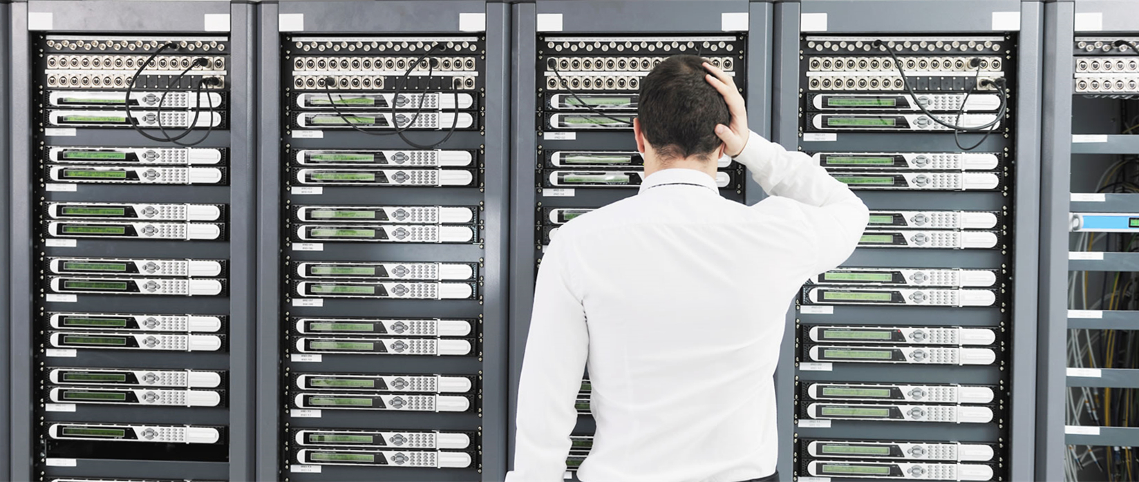
Generally speaking, data center is designed to keep the continuous operation of computer servers in an entire building or station. Likewise, server room is also devoted to this purpose but with a much smaller space. If you are only running a small business, then a small server room is enough. But you should not think that a small server room does not need proper building plan. Actually, having a solid design is very necessary to prevent future headaches. Well-organized server room ensures the effectiveness and viability of your business. This article will provide you with some considerations for setting up a small server room.

server-room

Select Right Sized Rack

With the growth of company, equipment may pile up day by day. It is dangerous to expose these equipment randomly to the working environment. A minor accident like coffee spill or stumble can cause great loss. Gladly, using server racks will effectively solve these unnecessary problems. But how to choose the suitable racks? Most importantly, server racks with sufficient inner space is beneficial to future equipment expansion. Today, server racks are usually in free-standing style or wall-mounted style. But you need to remember that no matter which type you choose, following the installation instructions can secure your racks from rack movement which may cause further disruption and damage.

server-racks

Isolate Servers to Prevent Noise

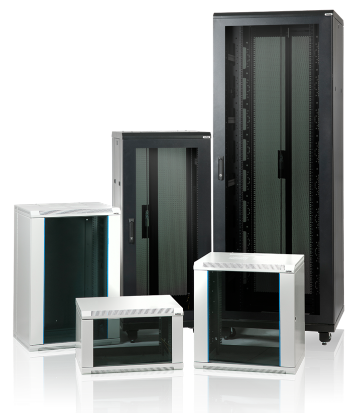
If budget permits, having a separate server room can both effectively reduce the equipment noise and secure the equipment from theft, physical tampering, and accidents. However, small company may have no choice but to place the rack in the corner of the room. Therefore racks with sound-dampening properties are welcome to be set up within such small areas. Completely soundproofing is impossible, but overall sound reduction can be achieved.

Get Control of the Heat

High temperature in your server rack will dramatically shorten equipment lifespan or even lead to crashes or outages. For the safety of the equipment, environment and company, you need cooling strategies to control the heat. Installing air-conditioning units is a good way to keep your equipment cool and lower the surrounding temperature. Also, a structured cabling will contribute to the heat control.

Keep Good Cable Management

Do not regard cable management as an unnecessary trifle. Sometimes it is the hidden danger in the future. You’d better keep good cable management right from the start. Properly bundling cables together behind equipment allows easier access to servers. When bundling your cables, it’s common practice to bundle by server and then group those bundles together. Related tools such as cable ties can be used to support the management process.

good-cable-management

Use Labels to Mark Everything

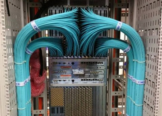
Another tip for managing your sever room in good order is to label all the cables. In this way, you can easily identify the right cable within a short time. Other accidents like systems being unplugged or restarted without warning can also be prohibited. When labeling your cables, you should include the information of where the cable connects to and from and a unique ID identifying the cable. Nowadays, many types of cable ties are available with the marking function.

Conclusion

Server room is an essential part of your company which contains all the important pieces that keep your business operating smoothly. Setting up a nice server room can keep your equipment away from damage and increase the working efficiency. Of course, if you are not professional, consulting a specialist for help is always recommended.

Field Terminated vs. Pre-Terminated: Which Do You Prefer?

Fiber optic termination refers to the addition of fiber optic connectors, such as LC, SC, FC, MPO, etc. to each fiber in a fiber optic cable. It is an essential step in fiber optic connectivity. Nowadays, two major termination solutions including field terminated and pre-terminated (factory pre-terminated) are used to achieve the fiber termination. For these two solutions, which do you prefer?

Field Termination

Field termination, as its name suggests, is to terminate the end of a fiber in the field. Field terminated solutions including no-epoxy, no-polish (NENP), epoxy-and-polish (EP) connectors and pigtail splicing are applied on the majority of fiber optic cables today. Field termination not only requires various of steps and tools, but also the proper training and skills of technicians to properly terminate the fiber.

field termination

Note: pigtail splicing is accomplished by fusing the field fiber with a factory-made pigtail in a splice tray.

Factory Termination

Factory termination, also called factory pre-termination, refers that cables and fibers are terminated with a connector in the factory. In fact, factory termination has the same procedures as field termination, but all the steps are taken at the manufacturers’ facility. The pre-terminated solution mainly including the fiber patch cables, the pre-terminated cassettes and enclosures features superior performance, good consistency, low insertion loss and good end-to-end attenuation in the system with the design of high-quality connector end-face geometry. In addition, by reducing the cumbersome process and tools, factory pre-terminated solution is easier to install and requires less technical skills.

factory pretermination

Field Terminated vs. Pre-Terminated

Field terminated solution and pre-terminated solution, with different strengths and weaknesses, are likely to attract different types of users. As technicians face important trade-offs in deciding which method to choose, we are going to provide a detailed comparison between them from several aspects in this section.

Preparation
Field terminated solution needs a series of preparations before termination. Procedures including stripping the cable, preparing the epoxy, applying the connector, scribe and polishing, inspection and testing are required. Additionally, tools and consumables such as epoxy and syringes, polishing products, cable installation tools, etc. are also necessary. Conversely, the pre-terminated solution doesn’t need any cable termination preparation, no connector scrap, no cumbersome tool kits or consumables and no specialized testers needed.

field terminated preparation

Cost & Time Spent
Traditional field terminated solution has the lowest material cost with no pre-terminated pigtails or assemblies required, but with the highest labor cost as it takes much longer to field install connectors. For pigtail splicing, though the factory pre-terminated pigtails cost less but the higher labor rates are typically required for technicians with fusion splicing equipment and expertise, or fusion splicing equipment and expertise must be on hand. The pre-terminated solution typically costs more than other options on materials. However, it greatly reduces the labor cost. Because less expertise and resources are required of installation staff.

As mentioned above, field terminated solution takes more time in preparation and connectors field installation. In contrast, with pre-terminated solution, connectors are factory terminated and tested in a clean environment with comprehensive quality control processes and documented test results that allows for immediate installation, saving up to 70% on installation time.

To sum up, mainly with time and labor saving, the pre-terminated solution can help users save cost at an average of 20-30% over field terminated solutions.

Performance
In terms of performance, the pre-terminated solution is more stable than the field terminated. Factory pre-terminated assemblies with documented test results are generally available in lower insertion loss and better performance. Field terminated solution works weaker in stability. Because there are many uncertainties in field installation. When for high density applications, the pre-terminated cable assemblies offer better manageability and density which are more suitable for high-density connectivity than the field terminated practices.

Applications
Field terminated solution, as a traditional termination method, is still used in many application fields. But now, for the case that cable distances are less than 100 meters and cable lengths are pre-determined, pre-terminated solution is more preferred by users. The pre-terminated solution is widely used for cross-connect or interconnect in the MDA (Main Distribution Area), EDA (Equipment Distribution Area), or other areas of the data centre, as well as for fixed lengths in the interbuilding or intrabuilding backbones.

Warm Tips: Click here to view the Field Termination vs. Factory Termination in LAN application.

Conclusion

Field terminated and factory pre-terminated solutions play a very important role in fiber optic termination, though they have different features. Choose the right method for your network according to your plan. For data center applications, FS.COM highly recommends you the pre-terminated solution as it can help keep costs down and network up, and meets the demands on high density. Contact us over sales@fs.com for detailed information.

Keyed LC System Secures Your Network

While we are chasing for higher data rates in fiber optic networks, data security is also an important concern for constructing good network environment. Data risks will increase in the expanded fiber optic networks when unauthorized or inadvertent data changes occur. In order to respond to the urgent demand, physically discrete fiber connection systems have emerged for security in high-performance fiber networks. Generally, we call it the keyed LC system. Data risks can be largely reduced at the early stage of the infrastructure design by using a new cabling solution of “keyed” characteristic. This article will take you to explore the world of keyed LC system.

What Is Keyed LC?

Keyed LC system or secure LC system is a small form factor (SFF) connection system that allows for physical segregation of network segments in secure fiber cabling infrastructure. Different colors are used in the system to identify different network circuits and protect them from accidental moves, adds, or changes. There are 8 or even 12 keying options for keyed LC components, thus 8 or 12 different colors are employed to correspond to the specific option. For instance, this picture shows the typical simplex keyed LC connectivity which only allows yellow colored interfaces to fit in with each other.

keyed-lc-connector-and-adapter

The following picture presents the 12 color coded patterns. Once the color does not match, the keying feature will prevent the connector from carrying the signal.

color-code-of-keyed-lc-products

Keyed LC System Components

Keyed LC system is a big family that contains various components. Most common members are keyed LC fiber optic connectors, keyed LC fiber patch cords, keyed LC fiber optic adapters, keyed LC fiber adapter panels and keyed LC fiber optic cassettes.

Keyed LC Fiber Optic Connectors & Patch Cords

Keyed LC connectors are varied in different colors. When connectors are linked to fiber cables, they combine to be the diverse keyed LC patch cables. These components are used in interconnecting or cross-connecting fiber networks within a structured cabling system. Keyed LC fiber patch cables in single-mode 9/125 um, multimode 62.5/125 um, 50/125 um and laser-optimized 50/125 um are frequently used in the network.

Keyed LC Fiber Optic Adapters

The front and back of keyed LC fiber optic adapters are both keyed to prevent installation errors and possible security breach. They have different color coded keyed patterns for identification and are available for both single-mode and multimode applications.

Keyed LC Fiber Adapter Panels

Keyed LC fiber adapter panels with 12, 16 and 24 fibers are available in the market. They are a widely recognized modular solution for restricted fiber cross-connect systems. In data center, equipment room and telecommunications room, keyed LC fiber adapter panels are now frequently used to improve data security levels.

Keyed LC Fiber Optic Cassettes

Keyed LC cassettes are widely applied to prevent unauthorized and inadvertent changes in the highly sensitive data center and IT network.

Benefits of Keyed LC Products
  • Point one — data security. It is the fundamental advantage of using keyed LC products. Data transmission is secured by multiple keying patterns. Networks can effectively be limited to certain groups, access levels or customers in a co-location environment, which provides an increased level of security and stability by protecting against incorrect patching of circuits.
  • Point two — easy identification. Color-coded keyed LC products are easy to be identified during cable installation and maintenance which saves lots of time.
  • Point three — higher performance.Keyed LC products are usually pre-terminated, which cause low insertion loss and greatly increase the fiber optic network performance.
  • Point four — flexibility. Two keyed simplex LC connectors can be easily assembled into a duplex LC connector. The polarity of a patch cord can also be reversed easily.
Summary

In conclusion, secure/keyed LC system is a modular connectivity system designed to secure fiber networks for higher performance. Great reliability can be achieved and installation becomes more efficient in all areas of a fiber cabling infrastructure.

What is FTTx Network?

FTTx

Since the customers have demanded for a more intensive bandwidth, the telecommunication carriers must seek to offer a matured network convergence and enable the revolution of consumer media device interaction. Hence, the emergence of FTTx technology is significant for people all over the world. FTTx, also called as fiber to the x, is a collective term for any broadband network architecture using optical fiber to provide all or part of the local loop used for last mile telecommunications. With different network destinations, FTTx can be categorized into several terminologies, such as FTTH, FTTN, FTTC, FTTB, FTTP, etc. The following parts will introduce the above terms at length.

FTTH

FTTx is commonly associated with residential FTTH (fiber to the home) services, and FTTH is certainly one of the fastest growing applications worldwide. In an FTTH deployment, optical cabling terminates at the boundary of the living space so as to reach the individual home and business office where families and officers can both utilize the network in an easier way.

FTTN

In a FTTN (fiber to the node) deployment, the optical fiber terminates in a cabinet which may be as much as a few miles from the customer premises. And the final connection from street cabinet to customer premises usually uses copper. FTTN is often an interim step toward full FTTH and is typically used to deliver advanced triple-play telecommunications services.

FTTC

In a FTTC (fiber to the curb) deployment, optical cabling usually terminates within 300 yards of the customer premises. Fiber cables are installed or utilized along the roadside from the central office to home or office. Using the FTTC technique, the last connection between the curb and home or office can use the coaxial cable. It replaces the old telephone service and enables the different communication services through a single line.

FTTB

In a FTTB (fiber to the building) deployment, optical cabling terminates at the buildings. Unlike FTTH which runs the fiber inside the subscriber’s apartment unit, FTTB only reaches the apartment building’s electrical room. The signal is conveyed to the final distance using any non-optical means, including twisted pair, coaxial cable, wireless, or power line communication. FTTB applies the dedicated access, thus the client can conveniently enjoy the 24-hour high speed Internet by installing a network card on the computer.

FTTP

FTTP (fiber to the premise) is a North American term used to include both FTTH and FTTB deployments. Optical fiber is used for an optical distribution network from the central office all the way to the premises occupied by the subscriber. Since the optical fiber cable can provide a higher bandwidth than copper cable over the last kilometer, operators usually use FTTP to provide voice, video and data services.

FTTx Network Applications

With its high bandwidth potential, FTTx has been closely coupled with triple play of voice, video and data services. And the world has now evolved beyond triple play to a converged multi-play services environment with a high bandwidth requirement. Applications like IPTV, VOIP, RF video, interactive online gaming, security, Internet web hosting, traditional Internet and even smart grid or smart home are widely used in FTTx network.

Conclusion

FTTx technology plays an important part in providing higher bandwidth for global networks. According to different network architectures, FTTx is divided into FTTH, FTTN, FTTC, FTTB, FTTP, etc. FS.COM provides FTTx solutions and tutorials for your project, please visit FS.COM for more information.

What Can Limit the Data Transmission Distance?

In the optical network, except the speed, data transmission distance is another important thing that we care. What can limit the transmission distance? At first we may think of fiber optic cable. Compared with copper cable, it can support longer transmission distance, high speed, high bandwidth, etc. However, not everything is perfect. Fiber optic cable still has some imperfections that influence the transmission distance. Besides, other transmitting media like transceivers, splices and connectors can also limit the transmission distance. The following will tell more details.

Fiber Optic Cable Type

Fiber optic cable can be divided into single-mode cable and multimode cable. The transmission distance supported by single-mode cable is longer than multimode cable. That’s because of the dispersion. Usually the transmission distance is influenced by dispersion. Dispersion includes chromatic dispersion and modal dispersion (as shown in the following figures). Chromatic dispersion is the the spreading of the signal over time resulting from the different speeds of light rays. Modal dispersion is the spreading of the signal over time resulting from the different propagation mode.

Chromatic-Dispersion

Modal-Dispersion

For single-mode fiber cable, it is chromatic dispersion that affects the transmission distance. This is because, the core of the single-mode fiber optic is much smaller than that of multimode fiber. So the transmission distance is longer than multimode fiber cable. For multimode fiber cable, modal dispersion is the main cause. Because of the fiber imperfections, these optical signals cannot arrive simultaneously and there is a delay between the fastest and the slowest modes, which causes the dispersion and limits the performance of multimode fiber cable.

Optic Transceiver Module

Like most of the terminals, fiber optic transceiver modules are electronic based. Transceiver modules play the role of EOE conversions (electrics-optics-electrics). The conversion of signals is largely depend on an LED (light emitting diode) or a laser diode inside the transceiver, which is the light source of fiber optic transceiver. The light source can also affect the transmission distance of a fiber optic link.

LED diode based transceivers can only support short distances and low data rate transmission. Thus, they cannot satisfy the increasing demand for higher data rate and longer transmission distance. For longer transmission distance and higher data rate, laser diode is used in most of the modern transceivers. The most commonly used laser sources in transceivers are Fabry Perot (FP) laser, Distributed Feedback (DFB) laser and Vertical-Cavity Surface-Emitting (VCSEL) laser. The following chart shows the main characteristics of these light sources.

Light Source Transmission Distance Transmission Speed Transmission Frequency Cost
LED Short Range


Low Speed Wide Spectral width Low Cost
FP Medium Range High Speed Medium Spectral Width Moderate Cost
DFB Long Range Very High Speed Narrow Spectral Width High Cost
VCSEL Medium Range High Speed Narrow Spectral Width Low Cost
Transmission Frequency

As the above chart mentioned, different laser sources support different frequencies. The maximum distance a fiber optic transmission system can support is affected by the frequency at which the fiber optic signal will be transmitted. Generally the higher the frequency, the longer distance the optical system can support. Thus, choosing the right frequency to transmit optical signals is necessary. Generally, multimode fiber system uses frequencies of 850 nm and 1300 nm, and 1300nm and 1550 nm are standard for single-mode system.

Bandwidth

Bandwidth is another important factor that influences the transmission distance. Usually, as the bandwidth increases, the transmission distance decreases proportionally. For instance, a fiber that can support 500 MHz bandwidth at a distance of one kilometer will only be able to support 250 MHz at 2 kilometers and 100 MHz at 5 kilometers. Due to the way in which light passes through them, single-mode fiber has an inherently higher bandwidth than multimode fiber.

Splice and Connector

Splice and connector are also the transmission distance decreasing reasons. Signal loss appears when optical signal passes through each splice or connector. The amount of the loss depends on the types, quality and number of connectors and splices.

All in all, the above content introduces so many factors limiting the transmission distance, like fiber optic cable type, transceiver module’s light source, transmission frequency, bandwidth, splice and connector. As to these factors, different methods and choices can be taken to increase the transmission distance. Meanwhile, equipment like repeater and optical amplifiers are also useful to support the long distance transmission. So there must be some ways to help you increase the transmission distance.

How to Prevent the Damage caused by Lightning in Fiber Cabling

With the development of the network communications, the optical fiber as a medium used in the integrated cabling systems to transmit data is used by more and more people, because of its advantages such as large transmission rate and distance. It is well known that optical fiber has no electrical conductivity and can prevent from impact current. Fiber optic cables have good protection performance, and the metal components of cable’s insulation value is so high that lightning current can not enter the cable easily. However, because fiber optic cable has strengthened core, especially the direct-buried fiber optic cable has armoring layer, thus when the optical fiber cable line experience lightning, the cables might be destroyed or damaged. And this blog talks about the main measures of lightning protection in fiber cabling.

Lightning Protection for Direct-Buried Fiber Optic Cables

  • Station Grounding Method: the metal part of the cables in the joints should be all connected to make sure the strengthened cores, moistureproof layers, and armoured layers are in connected state in the relay cable lines.
  • Electrical Disconnect Treatment should be done in the cable tapping of moistureproof layers, armoured layers and strengthened cores, and do not connect the ground for the insulation status. This method can avoid the accumulation of induced lightning current in the cables. Also, it can avoid lightning current enetr in the cables by grounding devices, which is caused by the difference of loop impedance to ground between the lightning discharge flow and the cables’ metal components.

Lightning Protection for Aerial Fiber Optic Cables

Aerial fiber optic cables should be electrical connected and connected to the ground every 2 km. The grounding can be directly done or or by suitable surge protection devices.

Typical Lightning Protection for Fiber Optic Cables

After fiber optic cables enter the fiber optic terminal boxes, the boxes should be connect to the ground so they can rapidly release the lightning current to realize the protection when the lightning current enter the fiber optic cables’ metal layers. When using direct-buried fiber optic cables with armoured layers and strengthened cores, the polyethylene outer sheath can be effectively anticorrosive and prevent from rat bites as well as the lightning stroke.

Article Source: http://www.fiberopticshare.com/how-to-prevent-the-damage-caused-by-lightning-in-fiber-cabling.html