Single Switch Vs. Multiple Switch: How to Select for Home Network?

Network switches are indispensable part on setting up a home network. For home Gigabit Ethernet switches, both one large single switch and multiple switch are good options. Using one large switch, the speed of data transferring could be faster but the problem is you have to run multiple lines throughout the house. Using multiple switches at home maybe redundant at some extent. So how to choose?

For choosing single large switch or multiple smaller switch applied to home network, it is not an easy question to answer. Because it involves various factors—size of the house, power consumption, fiber or copper, rack mount or not. Besides, you still need to consider how dense each part of the house will have networking. And then, in terms of this topic, we did some researches on some professional forums to investigate and congregate thoughts. Most of them prefer to use one larger switch rather than multiple smaller switches for home networking. The reasons are described in the following part.

switch stacking

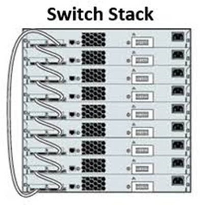
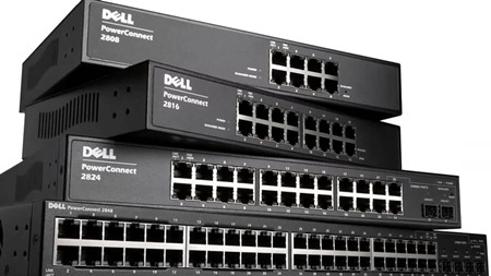
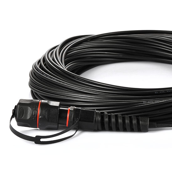
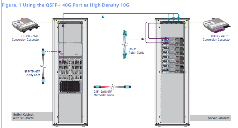
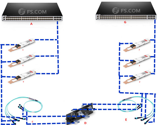
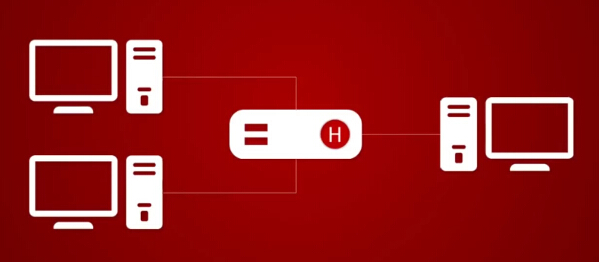
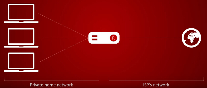
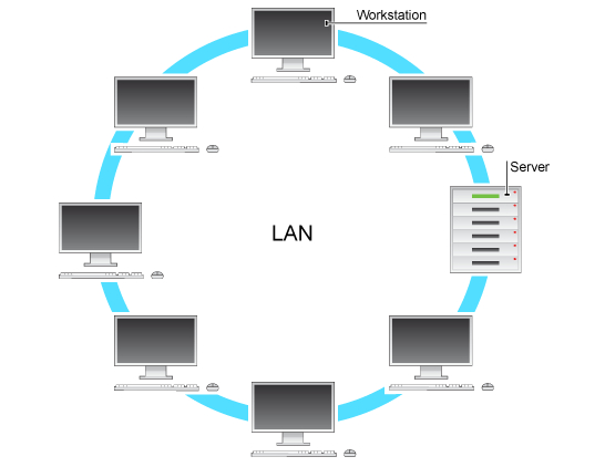
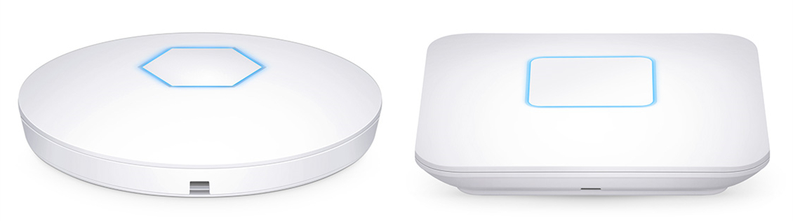
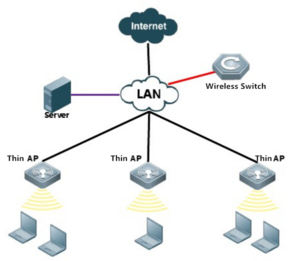
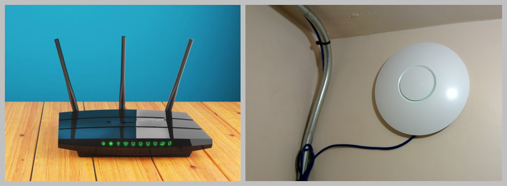
Figure1: multiple smaller switch stack

By using a central switch you will have UPS protection, unless you have an UPS at each location of course. And using a larger switch instead of multiple smaller ones, just because you will end up using less power that way. By using multiple switches, just make sure you buy two in case of hardware failure, that is the downside of centralizing everything to one device. So in that way, you will cost more to make sure the work of the hardware. In the below statement, we would list some merits and demerits to further clarify the reason why it is better to choose one large single switch instead of multiple smaller switches for home network.

Benefits of Using A Single Switch
  • A single switch will give you more security and better manageability, since it is centrally located.
  • In case of a small building, it is feasible to have a single optical switch catering to everyone. But if the building is big, then due to distance limitation of fast Ethernet, it may not be possible for one switch to cater to all the users. In this case, you will have to go for multiple switch solution.
  • One single switch will give you better performance than many switches. This is because in case of many switches, the inter-switch link is usually fast Ethernet or Gigabit Ethernet, but when you are using a single switch, switch backbone operates at much higher speeds.

So we can infer that if you have a small network, then you can start with single switch, and then as the network grows, you can migrate to multiple switch scenario. But if you are planning for a single switch situation, please think about a backup for this switch (either automatic failover or manual failover), so that in case of failure you can switch to the backup.

Weakness of Using Multiple Switches

First of all, using multiple switches dispatched in the different places is some sort of complexity. You need to connect all of them through some paths. And then, power consumption is also a big trouble. Using multiple switches inevitably brought much more power consumption than single switches. Besides, using multiple or redundant switch is common for security specially IP camera. If one of the switch breaks, then your other camera is still accessible. Then you have the distance limitation, which if this is the case, then you don’t have a choice but to implement more switch.

320px-Switched-fabric.svg

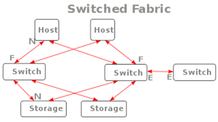
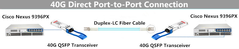
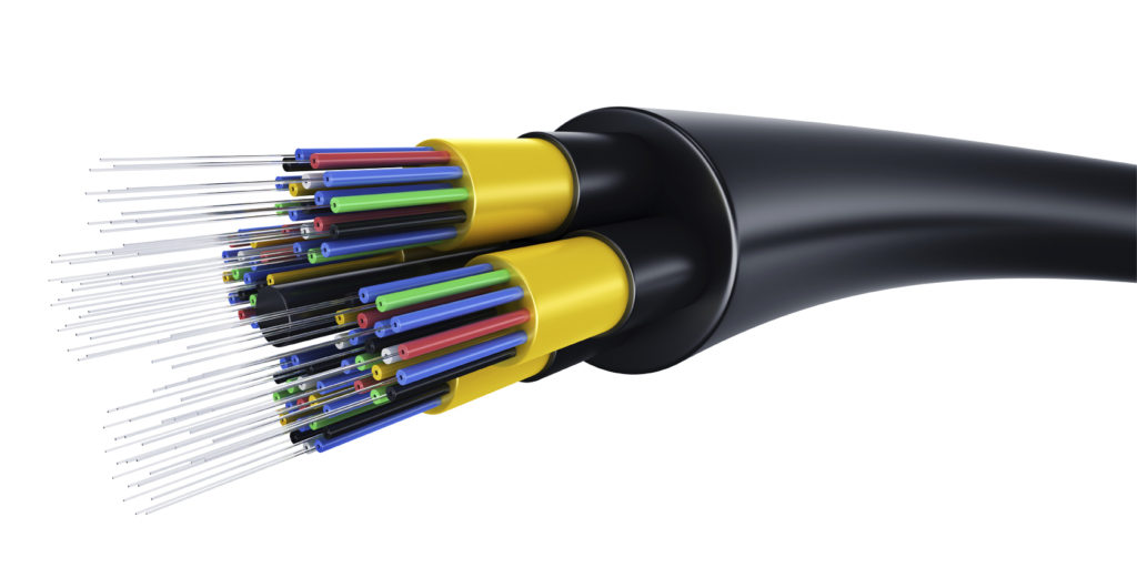
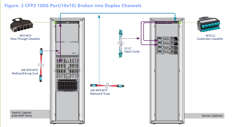
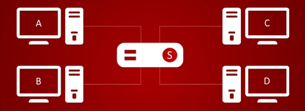
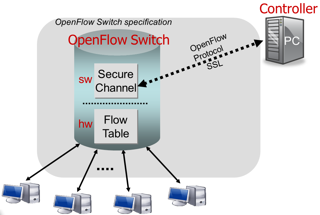
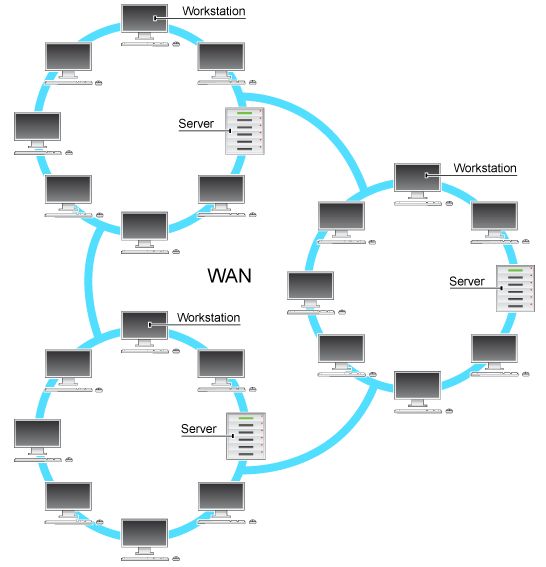
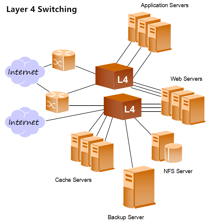
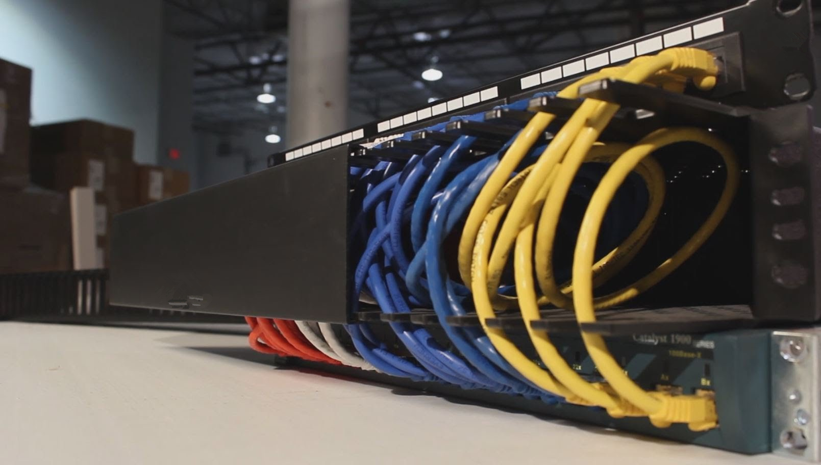
Figure2: fabric of multiple switches

Conclusion

According to the above description and analysis, we can draw a conclusion that using a single large network switches are better than using multiple smaller switches for home networking in most cases. But if you own an extremely larger house to meet your network requirement, and then multiple smaller switches would be good options.

Dell Powerconnect 2700 Vs. 2800 Series Switches

Both the Dell PowerConnect 2700 series and 2800 series switches are secure, fixed-port Gigabit switches. The Dell PowerConnect 2700 series was launched in the early 2000s, designed to deliver full wire-speed switching performance. Not long after the 2700 series, the 2800 series were released to support jumbo frames for networks that need to move large files across the network. They are both cost-effective solutions for small network environments, such as branch offices, schools and etc. However, it seems that it is hard to make a decision about purchasing these two series switches. This article would offer a satisfied solution to you and give a brief introduction to 2700 series and 2800 series switches.

Dell PowerConnect 2700 Series Switches

The Dell PowerConnect 2700 series switches are web-managed switches, the web-interface allows the user to easily manage the switch without learning CLI commands or integrating the switch into an SNMP-based application. These switches offer three port densities, including 8, 16, 24 and 48 Gigabit Ethernet 1 ports. Besides, the 2724 and 2748 have SFP slots in a combo port arrangement that deliver fiber capabilities. Auto MDI/MDIX and autonegotiation of speed, duplex mode and flow help deliver improved control over your network traffic. Totally, there are four models of 2700 series switch—Dell PowerConnect 2708, 2716, 2724, 2748. The main features of these switches are listed in the below:

  • There switches are prepared in advance for any elevated IT requirements.
  • They could eliminate the potential risks within the switch.
  • The 2700 series switches provide the flexibility to meet the requirement of various end users and applications environments.
  • They provide smartly balancing quality and the best prices.

dell-powerconnect-2716-overview

Figure1: Dell Powerconnect 2716 switch(Resource: www.DELL.com)

Dell PowerConnect 2800 Series Switches

As same as the 2700 Series Switch, Dell PowerConnect 2800 Series Switches are also web-managed Gigabit Ethernet switches. These switches offer four port densities, including 8, 16 , 24, and 48 port Gigabit Ethernet ports. In addition, the 2824 and 2848 have SFP slots in a combo port arrangement that deliver fiber capabilities (SFP transceivers optional). The PowerConnect 2800 family also supports jumbo frames for networks that need to move large files across the network. There are also four switch models of 2800 series switches—Dell PowerConnect 2808, 2816, 2824, and 2848. Main benefits of 2800 series switches are listed in the following.

  • Easy web access to the managed features provides a secure environment by offering password restricted access.
  • These switches offer enhanced security by allowing the user to specify which IP addresses have access to the switch.
  • The 2800 series switches support up to six link aggregation groups consisting of up to four ports per group.
  • Advanced cable diagnostics help improve network troubleshooting.

Dell 2800 series switch

Figure2: Dell 2800 Series Switches(Resource: www.DELL.com)

Dell 2700 Vs. 2800 Series switches

As being described, the Dell PowerConnect 2700 and 2800 series switches are nearly identical. But they still have some subtle differences in STP, management configuration, switching and price.

—Spanning Tree Protocol (STP)

Compared to Dell PowerConnect 2700 series switches, 2800 series support more STP protocols and support 9000 jumbo frames (not not 9014, etc.). If you do a ping -f on the 2724 with jumbo frames enabled it will go to 5000, 5500, 6000, but not 9000 – they get fragmented at that point. Granted that is only useful for iSCSI traffic, and even then it’s not 100% necessary. And the 9014+ jumbo frames is of the preference.

—Management Configuration

Both 2700 and 2800 series switches are small office switches with minimal management. They all not have LACP. BootP/DHCP IP address management or Static IP address assignment are set within the 2800 series switches. The 2800 series switches have CLI and SNMP Command Subset while the 2700 series switches do not.

—Switching

The link aggregation of both two series switches are up to eight aggregated links and up to eight member ports per aggregated link (IEEE 802.3ad). But the Jumbo frame of 2700 series switches support up to 9000 Bytes (2716, 2724, and 2748). The 2800 series switches have LACP support (IEEE 802.3ad).

—Price

Compared to 2700 series switches, 2800 series switches are cheaper. Just take the same 16-port switch for a example, a new Dell 2816 switch only needs $56 while a new Dell 2716 switch costs $112 on eBay.

Conclusion

Through this article, we are clear about the Dell 2700 and 2800 series Gigabit Ethernet switches as well as their differences in STP, management configuration, switching and price. They all powerful switches with outstanding cost and power savings. You can select an appropriate one according to your need.

QSFP-40G-UNIV vs QSFP-40G-SWDM4

Nowadays, the demand for high bandwidth increases and footprints for data center expands dramatically, which makes the migration from 10G to 40G much more necessary than ever before. Under this condition, many enterprises are ongoing or imminent to upgrade their data center network infrastructures. To better cater for our users, two transceivers 40G UNIV and 40G SWDM4 QSFP using SWDM (Short Wavelength Division Multiplexing) technology are compared in the following text, which intends to offer a cost effective transceiver solution for 10G to 40G migration applications. As parallel multimode MPO fiber cabling is much more expensive than Duplex-LC fiber cabling, Duplex-LC fiber patch cords will be used in these two SWDM applications, as a cost saving cabling method.

40G Direct Port-to-Port Connection

QSFP 40G UNIV Transceiver for SWDM Application

QSFP 40G UNIV is a kind of pluggable optical transceiver that fitted with Duplex-LC connector and can work with both single-mode and multimode fiber patch cable, originally released by Arista. Hence, it is also referred to as 40G SMF&MMF transceiver or 40G QSFP universal transceiver. When working with singlemode fiber, the Arista QSFP 40G UNIV can support 40G connection with a reach of 500m; and over OM3/OM4, the transmission distance can be up to 150m. Furthermore, the Arista QSFP 40G UNIV is designed with four 10G channels for transmitting and receiving four individual 10G signals through a single Duplex-LC fiber patch cord, for achieving a total 40G connection, as shown in the following figure.

Arista QSFP 40G UNIV

How does the Arista QSFP 40G UNIV work for 40G connection? The answer is SWDM technology. With the help of SWDM, Arista QSFP 40G UNIV will multiplex four wavelengths 1270nm, 1290nm, 1310nm and 1330nm to transmit four 10G signals over the single Duplex-LC fiber patch cord. And when the aggregate 40G signal passes through the receiver end, it will be demultiplexed into four individual 10G signals again. As a result, an aggregate 40G signal can be transmitted through a single Duplex-LC fiber patch cord. In short, Arista 40G universal transceiver is a very good choice for 40G migration which can work with LC-duplex single-mode or multimode fiber, instead of high-cost parallel multimode MPO fiber cabling.

QSFP 40G SWDM4 Transceiver for SWDM Application

QSFP 40G SWDM4 is an updated optical transceiver that basically works with Duplex-LC fiber patch cord for short 40G fiber link. It has the same working principle that uses SWDM technology as the QSFP 40G UNIV one, but can perform better. How does it do this? Unlike QSFP 40G UNIV working with both single-mode and multimode fiber, the QSFP 40G SWDM4 is designed to work with multimode fiber, which can transmit a multiplexed 40G signal over wide band OM5 at lengths up to 440m. It can also work in multimode fiber OM3 and OM4 with a reach of 240m and 350m, separately. What’s more, the power dissipation of QSFP 40G SWDM4 can be as low as 1.5W* since SWDM technology can match 4x WDM optical architecture with 4x electrical interface.

Similar to the QSFP 40G UNIV transceiver, four different wavelengths, 850nm, 880nm, 910nm and 940nm are used in the QSFP 40G SWDM4 transceiver. To transmit a total 40G signal, these four wavelengths will be multiplexed to carry four individual 10G signals, be transmitted through the Duplex-LC multimode fiber patch cord and finally demultiplexed. To better understand the principle of QSFP 40G SWDM4 transceiver, you can learn the above figure that illustrates how does the QSFP 40G SWDM4 work for a short distance 40G fiber link.

40G SWDM4 Transceivers

QSFP-40G-UNIV vs QSFP-40G-SWDM4, Which One is Better?

After discussion, we can learn that both QSFP 40G UNIV and QSFP 40G SWDM4 transceivers enable network operators to grow the capacity of their networks without laying new fiber cabling. In view of the transmission distance, QSFP 40G SWDM4 transceiver working with OM5 supports a longer 40G fiber link than QSFP 40G UNIV with OM3/OM4, but a shorter 40G fiber link than QSFP 40G UNIV with single mode fiber cable. When taking fiber cabling infrastructure cost into consideration, OM5 cabling costs about 50% more than OM4 and singlemode fiber is also very expensive. Then which one should be selected? Just depending on your network needs, such as the fiber link distance, the budget, etc. To better know the differences between QSFP 40G UNIV and QSFP 40G SWDM4 transceivers, here offers a table that shows their detailed parameters.

QSFP-40G-UNIV vs QSFP-40G-SWDM4

A Brief Overview of Fiber Optic Cable

Introduction

A fiber optic cable, also known as optical fiber cable, is a network cable that contains two or more glass or plastic fiber cores located within a protective coating and covered with a plastic PVC outer sleeve. It’s correlated with transmission of information as light pulses along a glass or plastic strand or fiber. It’s designed for long distance, very high performance data networking and telecommunications. It has many advantages in optical fiber communication, such as large capacity, long relay distance, good security, free from electromagnetic interference and copper saving.

fiber- optic- cable

Types of Fiber Optic Cables

According to the transmission mode of light in optical fiber, fiber optic cable can be divided into single-mode fiber (SMF) and multimode fiber (MMF). Although they all belong to optical cables and aim at transmitting information, they still have some slight differences.

SMF & MMF

Single-Mode Fiber

Literally, Single-mode fiber is a single stand of glass fiber with a diameter of 8.3 to 10 microns that has one mode of transmission. Due to its smaller diameter, single-mode fiber is used for long-distance signal transmission, which minimizes the reduction in signal strength. Single-mode fiber also has a considerably higher bandwidth than multimode fiber. The light source used for single-mode fiber is typically a laser, which makes it more expensive than multimode fiber.

Multimode Fiber

By comparison, multimode fiber cable, with a diameter of about 62.5 microns, allows multiple mode of light to propagate through it simultaneously, thus forming mode dispersion. Mode dispersion technology limits the bandwidth and distance of multimode fiber. Therefore, multimode fiber features larger core diameter and short transmission distance. Multimode fiber typically uses an LED to create the light pulse, which makes it cheaper than single-mode fiber.

Both single-mode and multimode fiber can handle 10G speeds. The most evident difference between them lies in the distance. Within a data center, it’s typical to use multimode fiber which can get you 300-400 meters. If you have very long runs or are connecting over longer distance, single-mode fiber can get you 10 km, 40 km, 80 km, or even farther. You just need to use the appropriate optic for the distance required.

Fiber Cable Uses

It’s widely acknowledged that optical cables are usually applied into computer networking and telecommunication due to its ability to transmit data and information. What’s more, it’s also used by military and space industries as means of communication and signal transfer, in addition to its ability to provide temperature sensing. In recent years, fiber cable is frequently used in a variety of medical instruments to provide precise illumination. An endoscope, for example, is a flexible tube containing several optical cables. When it slips into the patient’s mouth, nose, digestive tract, and other heart areas that are not visible outside the body, the doctor can see the changes through the endoscope. Other medical applications for fiber optics include X-ray imaging, biomedical sensors, light therapy and surgical microscopy.

Conclusion

From the aforementioned article, we can see that fiber optic cables have different types with different features, and are widely used in telecommunication, military, medical applications, etc. If you would like to know more or would like assistance in choosing the appropriate optical fiber cable, welcome to visit our website www.fs.com for more detailed information. FS will provide more choices and better services for our clients.

How to Select Waterproof Fiber Optic Patch Cable?

Fiber optic waterproof cables are widely used in outdoor applications to connect the major fiber optic lines or receivers or splice enclosures. According to different requirements, both fiber optic patch cords and fiber optic pigtails are available. Water proof fiber cable usually adds a water blocking material between the outer jacket and the inner fiber (or inner jacket) to protect the fiber surface from unwanted damage, such as an armored cable or loose-tube gel-filled cable, or water-tolerable tight-buffered cable. Since there are different types of structure for waterproof cables, is there an easy way to determine which waterproof fiber optic patch cable to choose? In order to help select a right waterproof fiber optic cable quickly, this post will introduce the basic knowledge of waterproof ratings and the features of our waterproof fiber optic cable.

LC-LC waterproof fiber patch cable

How Is a Waterproof Cable Rated?

Like choosing any other fiber optic patch cables, the connector type, fiber count, fiber type (single-mode or multimode), polish type, cable length and cable jacket are factors that should be considered as well. When buying waterproof fiber optic patch cords, the IP (International Protection or Ingress Protection) rating is an important parameter. Knowing the IP code can help you find your wanted waterproof cable.

IP rating system is a classification showing the degrees of protection from solid objects and liquids. IP rating codes do not include hyphens or spaces, and consist of the letters IP followed by one or two figures. The first number refers to the degree of protection against the entry of foreign solid objects, such as dust. These protection levels range from 0 to 6. The second number of the IP code refers to the degrees of protection against moisture/liquids, which are raging from 0 to 8. The first and second number of the IP code can be replaced by the letter “X” when the protection capacity against solid objects (the first number) or moisture (the second number) has not been tested, for example, IPX7 and IP6X.

The following two tables explain the two types of protection levels in details.

Table 1: Protection levels against solid objects.

IP Code Protection Object Size
0 No protection. N/A
1 Protection from contact with any large surface of the body, such as the back of a hand, but no protection against deliberate contact with a body part, such as a finger. Less than 50mm.
2 Protection from fingers or similar objects. Less than 12.5mm.
3 Protection from tools, thick wires or similar objects. Less than 2.5mm.
4 Protection from most wires, screws or similar objects. Less than 1mm.
5 Partial protection from contact with harmful dust. N/A
6 Partial protection from contact with harmful dust. N/A

Table 2: Protection levels against moisture.

IP Code Protection Test Duration Usage
0 No protection. N/A N/A
1 Protection against vertically dripping water. 10 mins Light rain.
2 Protection against vertically dripping water when device is tilted at an angle up to 15 degrees. 10 mins Light rain.
3 Protection against direct sprays of water when device is tilted at an angle up to 60 degrees. 5 mins Rain and spraying.
4 Protection from sprays and splashing of water in all directions. 5 mins Rain, spraying and splashing.
5 Protection from low-pressure water projected from a nozzle with a 6.3mm diameter opening in any direction. 3 mins from a distance of 3 meters Rain, splashing and direct contact with most kitchen/bathroom faucets.
6 Protection from water projected in powerful jets from a nozzle with a 12.5mm diameter opening in any direction. 3 mins from a distance of 3 meters Rain, splashing, direct contact with kitchen/bathroom faucets, outdoor use in rough sea conditions.
7 Protected from immersion in water with a depth of up to 1 meter (or 3.3 feet) for up to 30 mins. 30 mins Rain, splashing and accidental submersion.
8 Protected from immersion in water with a depth of more than 1 meter (manufacturer must specify exact depth). Varies Rain, splashing and accidental submersion.
Features of FS.COM Waterproof Fiber Optic Patch Cable

FS.COM provides IP67 waterproof fiber optic patch cable, including simplex, duplex, 12 fibers, 24 fibers, and various kinds of connect interfaces are optional, such as LC-LC fiber patch cord, SC-SC fiber patch cord, MPO-MPO fiber patch cord, etc. Other degrees of waterproof fiber optic patch cords can also be customized. Our waterproof fiber patch cables are designed with strong PU jacket and armored structure, which can resist high temperature and fit for harsh environment. Our IP67 waterproof fiber patch cords are featured with high temperature stability and low insertion loss. It is also very convenient to install these waterproof, dust-proof and corrosion-resistant patch cords. The plug and socket design can be used to extend the cable length. They are very suitable for FTTH (fiber to the home) and LAN (local area network) applications.

Conclusion

The IP code for waterproof devices is not that difficult to understand and you can get some basic information about the protection degree of a device after you know the meaning of each number. You can use it as a reference in choosing a waterproof cable, but you should also consider other factors according to your specific applications.

How to Deploy 10G, 40G, 100G in the Same Network

In 2010, 10G SFP+ became the primary equipment interface in data center applications. However, jump to 2017, as demand for greater bandwidth shows no signs of slowing, 40G and 100G transceiver shipments saw a whopping increase. While shipments of 40G and 100G modules are on the rise, the large majority of data center networks don’t undergo a whole replacement of 10G device with 40G or 100G device. Instead, many typically deploy necessary equipment to achieve the coexistence of 10G, 40G, and 100G in the same network. Read this post, and you will get detailed solution.

QSFP+ 40G to 10G

In the following scenario, an upgraded 40G switch is networked to existing 10G servers with a 1×24-fiber to 3×8-fiber MTP conversion cable. At the switch, a cassette combines three 40G ports (QSFP 8-fiber) on the 24-fiber trunk. In the server cabinet, each 40G port is segregated into 10G LC connections to support server connectivity.

QSFP+ 40G to 10G

Note: in this architecture, if you have existing 12-fiber MTP trunks, you can use a cassette with two 12-fiber MTP inputs that breakout into 3×8-fiber MTP strands, instead of deploying a new 24-fiber MTP trunk cable. However, if you have to move to denser and more complicated applications, the 24-fiber MTP solution makes for easier migration.

CFP2 100G Port (10×10)

Like the previous example, the following figure 2 also shows a similar scenario in existing 10G servers, but it uses 100Gbase-SR10 ports on the switch, which requires a 24-fiber connector to drive the 10×10 transceiver port. Instead of breaking into 8-fiber connections, it uses 24-fiber MTP fiber cable from the switch to the patch panel in the top of the rack. A 24-fiber MTP trunk connects the switch and server cabinet. The MTP cassette at the top of the server cabinet converts the 100G port into ten individual 10G port with LC connectors.

CFP2 100G port (10x10)

Note: As in the figure 1, in this scenario, if you already have two 12-fiber MTP trunks, you can use 12-fiber MTP adapter panel, then a 2×12-fiber to 1×24-fiber MTP harness cable could be used at the switch to build the same channel.

New Installation for 40G/100G Deployment

Figure 3 shows an example of a completely new installation, using 40G/100G right out of the box without any 10G switches in the channel. This method has 40G or 100G port on the core switches, and 40G uplinks at the ToR switches. The patch panels at the top of each rack use MTP bulkhead, with all 8-fiber cords from one QSFP port to the next.

40G100G Deployment - New Installation

In this architecture, we can either use 24-fiber trunks that break into 40G ports, or create trunks with 8-fiber strands on every leg, with 8 fibers per 40G or 100G port, as shown in the diagram above. However, we have to pay attention that with 8-fiber legs, the density will become a challenge. In addition, 12-fiber MTP trunks are avoided in this scenario, since integrating existing 12-fiber trunks with 8-fiber connectivity on the patch cord creates fibers unused.

Deploying 10G, 40G, 100G in the same network can effectively avoid costly upgrades that require ripping out cabling and starting over with a new network architecture. This post have provided three solutions. All the devices in these three scenarios can be purchased in FS.COM. If you are interested, kindly visit FS.COM.

100G QSFP28 and CFP Transceiver Cabling Solutions

By the end of 2016, 100G Ethernet has been widely deployed and becomes a significant portion in data center. Many network-equipment developers are motivated to introduce 100G devices like CFP and QSFP28 modules that consumes as little real estate and power as possible, while achieving necessary price points and delivering superior performance. This post is heading to talk about these two 100G modules and their cabling solutions.

CFP: Out With the Old

Specified by MSA among competing manufacturers, CFP is the first generation 100G transceiver which is designed after the SFP interface, but is significantly larger to support 100Gbps. As we all know, the original CFP has very large size, and in order to meet the need for higher performance and higher density in data center, there is the development of CFP2 and CFP4 specification, which specify a form-factor of 1/2 and 1/4 respectively in size of the original specification. Commonly used CFP/CFP2/CFP4 transceivers are available in 100GBase-SR10 and 100GBase-LR4.

100GBase-SR10 and 100GBase-LR4 CFP

QSFP28: In With the New

QSFP28 is the latest 100G form factor, which is a high-density, high-speed product solution designed for applications in the telecommunications, data center and networking markets. It utilizes four channels of respective signals with data rates up to 25Gbps to meet 100Gbps Ethernet requirement. 100GBase-SR4 and 100GBase-LR4 are two main types of QSFP28 module. The detailed specifications of these two QSFP28s are shown in the following table.

100GBase-SR4 and 100GBase-LR4 QSFP28

100GBase-SR10 Cabling Solution

100GBase-SR10 CFP uses a 24 strand MPO cable for connectivity (10 Tx and 10 Rx with each lane providing 10Gbps, leaving 4 channels unused). It can support maximum link length up to 100m and 150m respectively on OM3 and OM4 fiber cable. 100GBase-SR10 can also be used in 10×10 Gigabit Ethernet modes along with ribbon to duplex fiber breakout cables for connectivity to ten 10GBase-SR optical interface.

100GBase-SR10 CFP Cabling Solution

100GBase-SR4 Cabling Solution

Like 100GBase-SR10, 100GBase-SR4 QSFP28 also uses laser optimized OM3 and OM4 multimode fiber for indication. But 100GBase-SR4 QSFP28 utilizes 12f MPO trunk cable for connectivity (4 Tx and 4 Rx, leaving the middle four unused), which makes it possible to reuse 40GBase-SR4 fiber assemblies when upgrade from 40G to 100G.

100GBase-SR4 QSFP28 Cabling Solution

100GBase-LR4 Cabling Solution

Both 100GBase-LR4 CFP and QSFP28 are both interfaced with LC connector. They uses WDM technologies to achieve 100G transmission over single-mode duplex LC fiber patch cable supporting the link length up to 10km.

100GBase-LR4 Cabling Solution

Conclusion

As the need for high bandwidth is increasing, 100G Ethernet will widespread in data center quickly. Equipped with this basic information about 100G modules and their cabling solutions, we will have little worry upgrading to 100G Ethernet.

Related articles:
A Comprehensive Understanding of CFP Modules
QSFP-100G-SM-SR Vs QSFP-100G-CWDM4-S
Suggested 100G QSFP28 Transceiver Solutions for Data Centers

100% Fiber Utilization with 2×3 MTP Conversion Cable

When faced with eight-fiber parallel applications, such as 40GBase-SR4 40 Gigabit Ethernet and 100GBase-SR4 100 Gigabit Ethernet, technicians who use conventional 12-fiber MTP cable will waste a third of the fibers in the cable plant (four fibers for transmitting and four fibers for receiving, leaving the middle four unused). To overcome this inefficiency, new 2×3 MTP conversion harness is introduced. 2×3 MTP conversion cable terminated with three 8-fiber MTP connectors on one end and two 12-fiber MTP connectors on the other end can convert the signal from three four-channel transceivers to two 12-fiber trunks, which means 100% utilization of a 12-fiber network. The following text will mainly talk about how 2×3 MTP conversion cable uses all the fibers in 10G to 40G and 40G to 40G connection.

2x3 MTP conversion cable

10G to 40G Connection With 2×3 MTP Conversion Cable

Although upgrading from 10G to 40G Ethernet becomes common in most data centers, it is still impossible to replace all the 10G devices with 40G devices for more cost consumption. There are many solutions that we have introduced in the previous articles used to connect 10G to 40G equipment. 2×3 MTP conversion cable is a cost-effective one. The scenario can be clearly see from the following image. The three 8-fiber MTP connectors terminated at the 2×3 MTP conversion cable are directly plugged into the three 40GBase-SR4 modules(100% fiber utilization), then all cable assemblies will be plugged into the QSFP+ interfaced switch. The conversion from 40G to 10G is the most important step in this connectivity. Here we may use MTP or MPO LC cassette (2x12MTP-12xLC cassette) to connect two 12-fiber MTP connectors at the other end of the conversion cable to twelve duplex LC patch cables. Then all the LC cable assemblies with 10GBase-SR modules will be directly plugged into the SFP+ port switch. The whole connection do not waste any fiber.

10G to 40G connection with 2x3 MTP conversion cable

Identifier FS.COM Products Description
A S5850-48S6Q 48x 10GbE SFP+ with 6x 40GbE QSFP+ Switch
B QSFP-SR4-40G  QSFP+ SR4 optics; 150m @ OM4 MMF, 100m@ OM3 MMF
C 2×3 MTP Conversion Cable 2xMTP to 3xMTP; 50/125μm MM (OM3)
D 2x12MTP-12xLC cassette MTP-12 to LC UPC Duplex 24 Fibers MPO/MTP Cassette, 10G OM3, Polarity A
E Duplex LC Patch Cable Duplex LC; OM3
F SFP-10G-SR SFP SR optics; 300m over OM3 MMF
G S3800-24F4S 20x 100/1000Base SFP with 4x 1GE Combo and 4x 10GE SFP+ Switch
40G to 40G Connection With 2×3 MTP Conversion Cable

In this scenario, the three 8-fiber MTP connectors at the end of the conversion cable are directly plugged into the 40G module, then into 40G switch. In order to make sure all the fibers can be used in this 40G to 40G connectivity, we may use a adapter panel to connect the two 12-fiber MTP connectors of the conversion cable to the two 12-fiber MTP connectors attached at the end of the other 2×3 MTP conversion cable. Then the three 8-fiber MTP harness end with 40G modules will be plugged into the QSFP+ port switch. If you feel confused with my sentences, more clear description is shown in the image below.

40G to 40G connection with 2x3 MTP conversion cable

Identifier FS.COM Products Description
A S5850-48S6Q 48x 10GbE SFP+ with 6x 40GbE QSFP+ Switch
B QSFP-SR4-40G  QSFP+ SR4 optics; 150m @ OM4 MMF, 100m@ OM3 MMF
C 2×3 MTP Conversion Cable 2xMTP to 3xMTP; 50/125μm MM (OM3)
D MTP Adapter Panel Fiber Adapter Panel with 4 MTP(12/24F) Key-up/Key-down Adapters
E 2×3 MTP Conversion Cable 2xMTP to 3xMTP; 50/125μm MM (OM3)
F QSFP-SR4-40G QSFP+ SR4 optics; 150m @ OM4 MMF, 100m@ OM3 MMF
G S5850-48S6Q 48x 10GbE SFP+ with 6x 40GbE QSFP+ Switch
Conclusion

You can gain great value to deploy 2×3 MTP conversion cable, which does not add any connectivity to the link and it allows 100 percent fiber utilization and constitute the most commonly deployed method. However, you have to notice that the use of the 2×3 MTP conversion cable assembly at the core spine switch is not desirable, because patching across blades and chassis is a common practice.

What Should We Prepare for 40/100G Migration?

As data center of all types continue to grow in terms of traffic and size, 40/100G Ethernet technology is no longer a pipe dream—it is well on the way and set to become the new standard for high bandwidth and intelligent architecture. Faced with this upcoming trend in data center, what preparation should we do? Read this post, and you will get some details.

LC or MPO Interfaced 40/100G Modules?

Normally, there are two interfaces that 40/100G transceivers use: LC and MPO. LC interfaced modules will be used over single mode fiber for long distance data transmission, while MPO interfaced modules are commonly deployed with multimode fiber for short distance. However, there are also some transceivers not following this rule. For example, 40GBase-UNIV uses duplex LC connector, but it only supports 150 meters over OM3 or OM4 fiber, and 500 meters over single-mode fiber as we have mentioned in the previous post. Besides, 100GBase-PSM4 is a single-mode module, but it has MPO interface to achieve data transmission. Choosing LC or MPO interfaced 40/100G transceiver totally relies on the transmission distance that your practical application requires.

Type Fiber and Distance Connector
40GBase-SR4 100m(OM3) 150m(OM4) MPO(male/female)
40GBase-LR4 10km(SMF) Duplex LC
40GBase-UNIV 150m(OM3) 150m(OM4) 500m(SMF) Duplex LC
100GBase-SR4 100m(OM3) 150m(OM4) MPO (male/female)
100GBase-LR4 10km(SMF) Duplex LC
100GBase-PSM4 500m(SMF) MPO (male/female)
Keep Budgets Down with Pre-terminated Cabling System

Cost is always the most important factor that every IT managers and ordinary users will concern. Since the technology for 40G and 100G is not as mature as 10G, devices used in these high-speed networks are more expensive, so we should keep our budget down as possible as we can in every aspect in the process of 40/100G migration. Then pre-terminated cabling system is a good choice.

pre-terminated assemblies for 40/100G

Pre-terminated cabling system contains factory manufactured cables and modular components with connectors already attached. It comes in a number of different forms, from connectorized fan-outs and attached or discreet cassette modules to cable bundles utilizing both fiber and copper with protective pulling grips installed over the connectors at one end. With these pre-terminated cabling, the need for labor to make terminations on site will be mitigated. And fewer labor means more savings on the labor bill. As report indicates, using the pre-terminated approach can achieve a saving of 57 percent.

Punch Down Solution   Pre-terminated Cabling
Material Cost              1X            3.2X
Labor Cost              2X            1X
Total              1X            1.3X
Installation Time              10 Hrs            5 Hrs
Future-Proof Your Network with 24-Fiber Infrastructure

In many 40/100G cases, 12-fiber system is more recommended to use between core switched and the equipment distribution area in the data center, but actually, if you want to future-proof your network, try 24-fiber infrastructure. Why? Let’s have a quick comparison.

For typically 40GbE applications, the 4 right and 4 left fibers of a 12 fiber MPO connector are used for transmit and receive while the inner 4 fibers are left unused. For 24-fiber 40GbE application, all fibers are utilized in the MPO plug. 24 fibers, divided by the 8 fibers per circuit that are required, yields 3 full 40GbE connectors. For 100GbE applications, if we choose 12-fiber MPO connector, we need two connector and two MPO trunk cables, the middle 20 fibers are used for transmit and receive 10Gb/s while the 2 fibers on the right are left unused. However, in this case, we just need one MPO 24 connector and one 24f trunk cable. As data centers continue to be crowded with more cabling, with 24-fiber system, about 1-1/2 times more pathway space could be saved.

24 fiber system for 40/100G

Conclusion

With the rapid increase in bandwidth consumption, the migration from 10GbE to 40/100GbE is inevitable. Proper interfaced transceiver, pre-terminated cabling system and 24-fiber infrastructure are required to build a cost-effective and high density 40/100G data center. If you’re interested in the components that we have mentioned above, kindly visit FS.COM.

QSFP-40G-SR4 VS. QSFP-40G-UNIV

Due to the ever-increasing requirement for higher speed transmission, 40G Ethernet is introduced to networking world, and it will gradually dominates the market. Many vendors have released different kinds of devices to support 40GbE, among which 40G QSFP+ module is the most popular and available for short distance or long distance data transmission. There are two variants short distance QSFP+ modules: QSFP-40G-SR4, and QSFP-40G-UNIV, what are the differences among these two types? This passage will tell you and give more information.

Differences in Interfaces and Transmission Media

Commonly, for QSFP+ modules, there are mainly two connector interfaces: MPO/MTP and duplex LC(Note: LC interfaced QSFP+ uses serial transmission, while MPO/MTP interfaced QSFP+ uses parallel transmission. In serial transmission, bits are sent simultaneously on different channels within the same cable, and in parallel transmission, bits are sent sequentially on the same channel). QSFP-40G-SR4 uses MPO/MTP to achieve data transmission over multimode fiber. However, in order to avoid wasting cost and deployment time when installing in different cabling structure, duplex LC interfaced QSFP-40G-UNIV is designed to be used in both single-mode and multimode links without adding any hardware or software.

different interface between QSFP-40G-SR4 and QSFP-40G-UNIV

Differences in Working Principle

For MPO/MTP interfaced 40GBase-SR4, it offers 4 independent full-duplex transmit and receive channels, each capable of running up to 10G data rates per channel, achieving the total 40G data rates. These modules are often used with 12-fiber MTP trunk cable, four transmitting and four receiving, leaving the middle four unused. For duplex LC interfaced 40GBase-UNIV, it also uses four transmitters and four receivers but has built in optical multiplexing and de-multiplexing, which results in a duplex connector and hence operates over the same duplex fiber infrastructure as 10GBASE-SR.

different working principle of QSFP-40G-SR4 and QSFP-40G-UNIV

Differences in Transmission Distance

40GBase-SR4 module can support link lengths of 100 meters and 150 meters, respectively, on laser-optimized mutimode fibers, and it can also be used in a 4x10G mode interoperability with 10GBase-SR interfaces up to 100 and 150 meters on OM3 and OM4 fibers, respectively. 40GBase-UNIV can support the same transmission distance over OM3 and OM4 fibers, but it can also achieve link lengths of up to 500 meters over single-mode fiber.

Differences in Cost Consumption

40GBase-UNIV is much more expensive than 40GBase-SR4. Take FS.COM for example, 40GBase-UNIV is $340, while 40GBase-SR4 is $55. Besides the price of the unit itself, we should also take the whole deployment cost consumption into consideration. Migrating from 10G to 40G is inevitable. The existing 10G network uses two fibers for dual transmission. But most 40G network uses 12-fiber MTP based fiber optic cable for dual-way transmission over multimode fibers, which means if we use 40GBase-SR4 with MTP port for 10G to 40G migration, more optical fibers will be added and the cabling infrastructure will be changed. However, with 40GBase-UNIV module, it can support the same or longer transmission distance as the 40GBase-SR4 does, but it uses two strands of dual-way transmission like most 10G network, which will keep the existing 10G network when upgrade to 40G, greatly saving cost and time.

10G to 40G migration with QSFP-40G-SR4 and QSFP-40G-UNIV

Conclusion

We have introduced QSFP-40G-SR4 and QSFP-40G-UNIV modules for short distances transmission. These two module types have different features. Choosing which one totally depends on your practical applications and budgets. FS.COM has plenty of QSFP-40G-SR4 and QSFP-40G-UNIV optics in stock. For more information, please check FS.COM.

Some Thoughts Required Before MTP Cabling

To meet system bandwidth needs and provide higher density cable connectivity, building backbones and data center backbones are migrating to 40G and 100G Ethernet network. Making the migration path smooth has become a hotspot. Network designers are turning to MTP components which can provide cost-effective solutions for cabling systems of data centers. We know that MTP components are designed with complex structures, so before you start your 40G Ethernet network deployment, there are a few aspects of MTP cabling that require some thoughts.

Polarity

First and foremost is the polarity. With the LC connector typically used for 1G and 10G fiber cables, this isn’t a big deal. You can flip the two fiber strands on the LC connector easily to invert the polarity if needed. However, the MTP connector is fixed, you can’t change the ordering of the strands in the connector. Take 12-fiber MTP trunk cable for example, it is made up of 12x individual strands of fiber and one 12-fiber MTP connector on each end. Typically in 40G Ethernet network deployment, the 12-fiber MTP cable transmits optic signals on first 4x strands, and receives optic signals on the last 4x strands. The 4x “transmit” strands in MTP connector on one end need to end up at the “receive” strands in MTP connector on the other end. In other words, 8 of the 12 fibers are used to provide 40G parallel transmission and the polarity of the cable has to be inverted between the two devices. In addition, there are three polarity methods for MTP cabling. Each of them has different features. It is recommended that a method be selected in advance according to the specific requirements of the cabling situation and maintained consistently throughout an installation.

Gender of MTP Connector

Another issue with MTP components to take into consideration is the gender of the connector going into the adapter matter. There are male connector and female connector. And the former one has pins while the latter one has no pins. One cable going into a MTP adapter needs to have a male connector and the other cable must have a female connector. This is not initially obvious to those who have little knowledge about MTP components. If you only have MTP cables with female connectors, they can be snapped into the adapter just fine, but will not work. The figure below shows the difference between the structure of male and female MTP connector.

male and female MTP connector in MTP cabling

Key Position of MTP Adapter

MTP adapter, or MTP coupler, is simple plastic rectangle that holds two MTP connectors together. The other important factor to note about MTP adapter is that they can be either key-up to key-up, or key-up to key-down, and this corresponds to the key position of MTP connector. When the key sits on top, this is referred to as the key up position. On the contrary, when the key sits on bottom, we call it key down position. On a key-up to key-up adapter, the keys are pointed the same direction on both of the connectors. While on a key-up to key-down adapter, the keys are on opposite sides. This can effect the polarity of the fiber link. To have a better understanding of this, here is a figure for you.

key position of MTP adapter in MTP cabling

Conclusion

Being able to provide an easy migration path for higher data rates that will require parallel optics such as 40/100G Ethernet network, MTP cabling is commonly used by network designers to satisfy the increasing demands for higher transmission speed and cabling density. However, before the installation, three major problems—polarity, gender of MTP connector and key position of MTP adapter have to be solved to ensure the smooth data transmission over the optical links.

Can We Use Base-8 and Base-12 Together?

Although 10 Gigabit Ethernet is still marketing its way into the data centers, the need for faster data transfer rates is relentless, which means the migration to 40 Gigabit Ethernet is becoming inescapably compelling. For 40G Ethernet network, there are mainly two connectivity methods, one is Base-8, and the other is Base-12. Base-12 connectivity has had its place in the data center, while Base-8 is a new connectivity that could gain widespread acceptance in the next few years. With these two methods existing in 40G Ethernet network, there comes problems: Which one is more suitable for 40G network, or can we both use these two methods in 40G network? Read this articles, and you will get the detailed answers.

Base-12 Dominates the Market

Base-2 connectivity is the most commonly used one in the past, but as the data center grew to thousands of fiber ports engaged, stringing two-fiber patch cords across all corners of the data center will result in an unmanageable, and unreliable mess. So Base-12 connectivity is introduced. It is designed to develop a modular, high density, structured cabling system which could be deployed in data centers quickly, while also maximizing port densities within the rack space. In this connectivity method, all the fiber optic cables are based on an increment of 12 fiber, like 12-fiber or 24-fiber MTP trunk cable.

Base-12 system using a 24-fiber trunk cable

Base-8 Shines the Light

Base-12 connectivity is common in data center, but here comes a problem when installed it in a parallel system. For example, if we need to use 40GBase-SR4 optics implemented in a 12-fiber infrastructure, four fibers for transmit, and four fibers for receive, leaving four fibers unused per connection, this will lead to a significant and costly loss in fiber network utilization. But Base-8 can be a more cost-effective option for end-to-end MPO to MPO channels and architectures. With 8-fiber infrastructure, the 40GBase-SR4 module will use all the 8 fibers. Base-8 connectivity makes use of fiber links in increment of 8 versus 12. The 12-fiber trunk cables are replaced with trunk cables in increment of 8: 8-fiber, 16-fiber, or 24-fiber trunk cables, etc.

Base-8 system using a 24-fiber trunk cable

Can We Use Base-8 and Base-12 Together?

Although using Base-8 connectivity could decrease fiber consuming in supporting 40G data rates, in fact, in many cases, Base-8 connectivity isn’t a universal solution, and Base-12 may still be more cost-effective. So is it possible to have both Base-8 and Base-12 connectivity in the same data center? The answer could be “Yes” or “No”.

Base-8 and Base-12 Fiber Links Cannot Be Mixed and Matched

It is never possible to directly mix the components of Base-8 and Base-12 connectivity, or plug a Base-8 trunk into a 12-fiber module. Because a Base-12 trunk cable normally has unpinned MTP connector on both ends, and requires the use of pinned 12-fiber breakout modules, while a Base-8 trunk cable is manufactured with pinned MTP connectors at both ends (pinned and unpinned MTP connectors are shown below). So if we plug a Base-8 trunk into a 12-fiber breakout module, just like trying to mate two pinned connectors together, this connection will definitely not work, and vice verse.

pinned and unpinned MTP connector

Base-8 and Base-12 Can be Maintained in the Same Data Center Separately

It is possible to deploy both Base-8 and Base-12 connectivity within the same data center, just as long as the links are separate. Since Base-8 and Base-12 components are not interchangeable, during managing the data center physical layer infrastructure, we should do careful management and labeling practice to ensure we will not mix or mismatch them.

Conclusion

Base-12 connectivity has dominated the 40G network market for years, while the Base-8 connectivity is an additional option in the network designer’s tool kit to ensure that data centers have the most cost-effective, future-proof network available. When using Base-8 and Base-12 in network, make sure that you need to carefully manage and label them, and that the components in Base-8 and Base-12 won’t be mixed.

Suggested 100G QSFP28 Transceiver Solutions for Data Centers

In recent years, QSFP28 transceiver module has upgraded the 100G market which can support the data transmission mode of 4×25G. Currently many data centers have already adopted QSFP28 transceiver for 100G migration. Of course, there are many other types of transceivers can transfer the 100G network, but QSFP28 modules are still considered to be the optimal choice. This post is going to present some useful 100G QSFP28 transceiver solutions for data centers. Maybe one of them is exactly what you need.

Basics of QSFP28 Transceiver

QSFP28 transceiver is designed for high-density and high-speed for applications in telecommunications. The transceiver offers four channels of different signals with data rates ranging from 25 Gbps up to potentially 40 Gbps, and meets 100 Gbps Ethernet (4×25 Gbps) and 100 Gbps 4X InfiniBand Enhanced Data Rate (EDR) requirements. QSFP28 optical transceiver has various advantages. It has a smaller size than other 100G modules, thus it is ideal for high-density ports on the switch. Power consumption of QSFP28 transceiver is usually the lowest of less than 3.5W. In addition, QSFP28 increases the transmission capacity of every lane from 10G to 25G, which can save much cost for each bit.

QSFP28 Transceiver Solutions

QSFP28 transceivers can be categorized into several types based on different IEEE (Institute of Electrical and Electronics Engineers ) or MSA (Multi-source Agreement) standards.

QSFP-100G-SR4 is the IEEE standard for 100G QSFP28 that supports short distance over multimode. It can reach 100G transmission up to 70m over OM3 and 100m over OM4. With the MTP/MPO interface, QSFP-100G-SR4 QSFP28 transceiver supports four lanes of 25G dual way transmission over eight fibers.

qsfp28 transceiver

QSFP-100G-LR4 is also the IEEE standard for QSFP28 module but supports long distance transmission for the maximum of 10km over single-mode fiber. QSFP-100G-LR4 is special for adopting the WDM technologies for four 25G lanes transmission over four different wavelengths. In addition, its duplex LC interface supports the 100G dual-way transmission.

qsfp28-lr4

100GBASE-PSM4 is the standard defined by MSA for the point-to-point 100G link over eight single-mode fibers reaching the length of up to 500m. 100GBASE-PSM4 QSFP28 transceiver uses four identical and independent lanes for each signal direction with each lane carrying a 25G optical transmission. With the MTP/MPO interface, optical fiber ribbon cables with MTP/MPO connectors can be plugged into the QSFP28 module.

qsfp28-psm4

100GBASE-CWDM4 standard was released by CWDM MSA to support 100G network for up to 2km. It uses the CWDM technology to reduce the transmission on 8 fibers (4 optical transmitters and four optical receivers) into 2 fibers. This transceiver is similar to QSFP-100G-LR4 but has a shorter transmission range and lower cost.

qsfp28-cwdm4

Conclusion

In a word, QSFP28 modules are suggested transceiver solutions for upgrading the data center 100G network. The QSFP-100G-SR4, QSFP-100G-LR4, 100GBASE-PSM4, and 100GBASE-CWDM4 QSFP28 transceivers mentioned above are the most popular ones to ensure the high-speed data transmission at either short or long distance. FS.COM offers both generic and compatible QSFP28 modules according to your demands. Other than QSFP28 transceivers, there are also many other types of 100G transceiver, such as CFP, CFP2, CFP4, CXP transceivers. For more information, please kindly visit FS.COM or contact us directly via sales@fs.com.

Do You Know the Difference Between Hub, Switch & Router?

When computers, network devices or other networks are required to be connected, hubs, network switches and routers are the bridges to link them together. All the three types of devices can perform the same function, and technicians sometimes may use the terms interchangeably. However, this will make people confuse whether they are the same thing or different from each other. This post is going to explore the actual meanings of hub, switch, router and what they are used for.

Overview of Hub, Switch & Router
Hub

A hub is to sent out a message from one port to other ports. For example, if there are three computers of A, B, C, the message sent by a hub for computer A will also come to the other computers. But only computer A will respond and the response will also go out to every other port on the hub. Therefore, all the computers can receive the message and computers themselves need to decide whether to accept the message.

hub network

Switch

A switch is able to handle the data and knows the specific addresses to send the message. It can decide which computer is the message intended for and send the message directly to the right computer. The efficiency of switch has been greatly improved, thus providing a faster network speed.

switch network

Router

Router is actually a small computer that can be programmed to handle and route the network traffic. It usually connects at least two networks together, such as two LANs, two WANs or a LAN and its ISP network. Routers can calculate the best route for sending data and communicate with each other by protocols.

router network

What Is the Difference?
Hub Vs. Switch

A hub works on the physical layer (Layer 1) of OSI model while Switch works on the data link layer (Layer 2). Switch is more efficient than the hub. A switch can join multiple computers within one LAN, and a hub just connects multiple Ethernet devices together as a single segment. Switch is smarter than hub to determine the target of the forwarding data. Since switch has a higher performance, its cost will also become more expensive.

Switch Vs. Router

In the OSI model, router is working on a higher level of network layer (Layer 3) than switch. Router is very different from the switch because it is for routing packet to other networks. It is also more intelligent and sophisticated to serve as an intermediate destination to connect multiple area networks together. A switch is only used for wired network, yet a router can also link with the wireless network. With much more functions, a router definitely costs higher than a switch.

Hub Vs. Router

As mentioned above, a hub only contains the basic function of a switch. Hence, differences between hub and router are even bigger. For instance, hub is a passive device without software while router is a networking device, and data transmission form in hub is in electrical signal or bits while in router it is in form of packet.

Which One Should I Buy?

Whatever device you use for your network, you must make sure it can perform all the functions required by the network. As for performance, wireless router is recommended because it allows different devices to connect to the network. If you have a limited budget, switch is a good solution with relatively high performance and lower cost.

Conclusion

Although sometimes specialists alternatively use hub, switch or router to describe these devices, they still have their own differences. Understanding their distinctions can be helpful to find the most appropriate device for your network.

How Will SDN Change the Future Network?

Traditional networks are usually built with tiers of Ethernet switches in a tree structure. However, the development of mobile devices, server virtualization and cloud computing service has driven the need for dynamic computing and storage in data centers. Thus, the concept of software-defined networking (SDN) was put forward to construct a more flexible and agile network. This technology has widely caught people’s attention in the industry over the years. In this post, some basic knowledge about SDN will be introduced to help you have better understanding.

Definition of SDN Architecture

SDN is a developing network architecture that aims to directly program the network computing. Through the open interfaces and abstraction of lower-level functionality, this approach allows the network administrators to programmatically initialize, control, change and manage network behavior dynamically. SDN is different from the traditional network architecture whose network devices are based on both control plane and data plane. Instead, SDN puts the control plane on the SDN controller to communicate with a physical or virtual switch data plane through the OpenFlow protocol.

sdn-architecture

Features of SDN

Here are some fundamental features of the SDN architecture:

  • Instantly programmable: Network control is directly programmable for it is decoupled from forwarding functions.
  • Agile: Administrators can dynamically adjust network-wide traffic flow to meet changing needs.
  • Centralized management: Network intelligence is centralized in SDN controllers that maintain a global view of the network.
  • Programmatically configured: Network managers can configure, manage, secure, and optimize network resources very quickly by dynamic, automated SDN programs.
  • Open standards-based and vendor-neutral: SDN simplifies network design and operation since instructions are provided by SDN controllers instead of multiple, vendor-specific devices and protocols.
Basics of OpenFlow

OpenFlow is a type of communication protocol that provides access to the forwarding plane of a network switch or router over the network. It is considered to be the first SDN standard, which enables network controllers to determine the path of network packets across a network of switches. In order to work in an OpenFlow environment, all the equipment should support the OpenFlow protocol to communicate to an SDN controller.

openflow

What Benefits Will OpenFlow-Based SDN Bring to Network?
  • Point 1, SDN controller can get centralized control of OpenFlow-enabled devices from any vendors instead of managing the devices from different vendors separately.
  • Point 2, OpenFlow-based SDN provides a flexible network automation and management architecture, and can develop a variety of automated network management tools to replace the current manual operation which greatly reduces the complexity.
  • Point 3, SDN increases higher rates of business innovation and allows IT network operators to meet specific business needs and variable user needs in real time by explicitly programming or reprogramming the network.
  • Point 4, SDN enables IT to define the configuration network and develop management policies at a higher level and distributes the information to the network infrastructure through OpenFlow, which has increased the network reliability and security.
  • Point 5, OpenFlow’s flow control model allows IT to deploy network policies at a granular level which is a higher abstraction and automated deployment level including session-level, user-level, device-level and application-level.
  • Point 6, through centralized network control and network application status information, SDN can provide better dynamic user experience.
Conclusion

Future network will depend on more and more software to accelerate the pace of network innovation. SDN is committed to changing the current static network into a dynamic and programmable one. With so many advantages and industrial potentiality, SDN will definitely become the new standard of future network.

Computer Networks Comparison Between LAN & WAN

When setting up the wireless router at home, you may notice that there are different ports at the back of router noted with LAN or WAN. If you are totally new to this, then understanding the differences between LAN and WAN technologies is fairly important. This article will solve your confusion about these network terms.

LAN-WAN

What Is LAN?

LAN is the abbreviation of local area network. As a simple and original network, LAN is widely used in different kinds of places for short range computer connections. It is a computer network built within a restricted area. LAN network has its own network devices and local interconnections. Applications of LAN can always be found in the residence, school, laboratory, university campus or office. All the computers are linked in the same general location. A local area network is considered to be private and maintained by a single group of people.

local area network

What Is WAN?

WAN refers to wide area network. It is a computer network with a large geographical coverage. The essence of WAN is to allow a network to be carried out without the limitation of location. The Internet that we use every day is a good example of WAN network. As its name suggests, WAN is very wide that can across a town, a region, a country or even the whole world. It is often used by business and government agencies to make strong network communication among employees, clients, supplier and buyers from various parts of the world.

wide area network

Differences Between LAN & WAN

Here are some major differences between LAN and WAN computer networks.

  • Point 1, cover ranges of LAN and WAN networks are different. LAN connects computers in a small physical area, while WAN connects larger areas situated in different geographical locations.
  • Point 2, network speeds of LAN and WAN are varied. WAN is typically slower than LAN due to the distance data must travel. The maximum speed of LAN is 1000 Mbps while WAN can only reach 150 Mbps.
  • Point 3, as for the security level, LAN seems to be better than WAN. Because WAN involves more people into the interconnection, there is a greater possibility of network issues.
  • Point 4, due to the smaller network coverage, setup and maintenance costs for LAN are usually lower than WAN.
Other Computer Network Types

Apart from the common LAN and WAN computer networks, there are also many other types.

WLAN: wireless local area network is a type of LAN that uses wireless technology to connect computers or devices to the router.

MAN: metropolitan area network is larger than LAN and smaller than WAN to connect nodes located in the same metro area.

SAN: storage area network provides access to consolidated, block level data storage. It does not rely on a LAN or WAN.

VPN: virtual private network help users to access a private network remotely through a virtual point-to-point connection.

EPN:enterprise private network is a computer network built by a business to interconnect its various locations to share computer resources.

PAN:personal area network is the smallest and most basic network for data transmission among personal devices.

Conclusion

LAN and WAN are the most widely used computer networks in today’s world. Both of them have their own advantages and disadvantages. When you are confused about which network to set up, network distance is a good aspect to consider. Although LAN has many benefits, you still need to choose WAN when it comes to large areas networking.

Layer 2, Layer 3 & Layer 4 Switch: What’s the Difference?

Network switches are always seen in data centers for data transmission. Many technical terms are used with the switches. Have you ever noticed that they are often described as Layer 2, Layer 3 or even Layer 4 switch? What are the differences among these technologies? Which layer is better for deployment? Let’s explore the answers through this post.

What Does “Layer” Mean?

In the context of computer networking and communication protocols, the term “layer” is commonly associated with the OSI (Open Systems Interconnection) model, which is a conceptual framework that standardizes the functions of a telecommunication or computing system into seven abstraction layers. Each layer in the OSI model represents a specific set of tasks and functionalities, and these layers work together to facilitate communication between devices on a network.

The OSI model is divided into seven layers, each responsible for a specific aspect of network communication. These layers, from the lowest to the highest, are the Physical layer, Data Link layer, Network layer, Transport layer, Session layer, Presentation layer, and Application layer. The layering concept helps in designing and understanding complex network architectures by breaking down the communication process into manageable and modular components.

In practical terms, the “layer” concept can be seen in various networking devices and protocols. For instance, when discussing switches or routers, the terms Layer 2, Layer 3, or Layer 4 refer to the specific layer of the OSI model at which these devices operate. Layer 2 devices operate at the Data Link layer, dealing with MAC addresses, while Layer 3 devices operate at the Network layer, handling IP addresses and routing. Therefore, switches working on different layers of OSI model are described as Lay 2, Layer 3 or Layer 4 switches.

OSI model

Switch Layers

Layer 2 Switching

Layer 2 is also known as the data link layer. It is the second layer of OSI model. This layer transfers data between adjacent network nodes in a WAN or between nodes on the same LAN segment. It is a way to transfer data between network entities and detect or correct errors happened in the physical layer. Layer 2 switching uses the local and permanent MAC (Media Access Control) address to send data around a local area on a switch.

layer 2 switching

Layer 3 Switching

Layer 3 is the network layer in the OSI model for computer networking. Layer 3 switches are the fast routers for Layer 3 forwarding in hardware. It provides the approach to transfer variable-length data sequences from a source to a destination host through one or more networks. Layer 3 switching uses the IP (Internet Protocol) address to send information between extensive networks. IP address shows the virtual address in the physical world which resembles the means that your mailing address tells a mail carrier how to find you.

layer 3 switching

Layer 4 Switching

As the middle layer of OSI model, Layer 4 is the transport layer. This layer provides several services including connection-oriented data stream support, reliability, flow control, and multiplexing. Layer 4 uses the protocol of TCP (Transmission Control Protocol) and UDP (User Datagram Protocol) which include the port number information in the header to identify the application of the packet. It is especially useful for dealing with network traffic since many applications adopt designated ports.

layer 4 switching

Which Layer to Use?

The decision to use Layer 2, Layer 3, or Layer 4 switches depends on the specific requirements and characteristics of your network. Each type of switch operates at a different layer of the OSI model, offering distinct functionalities:

Layer 2 Switches:

Use Case: Layer 2 switches are appropriate for smaller networks or local segments where the primary concern is local connectivity within the same broadcast domain.

Example Scenario: In a small office or department with a single subnet, where devices need to communicate within the same local network, a Layer 2 switch is suitable.

Layer 3 Switches:

Use Case: Layer 3 switches are suitable for larger networks that require routing between different subnets or VLANs.

Example Scenario: In an enterprise environment with multiple departments or segments that need to communicate with each other, a Layer 3 switch facilitates routing between subnets.

Layer 4 Switches:

Use Case: Layer 4 switches are used when more advanced traffic management and control based on application-level information, such as port numbers, are necessary.

Example Scenario: In a data center where optimizing the flow of data, load balancing, and directing traffic based on specific applications (e.g., HTTP or HTTPS) are crucial, Layer 4 switches can be beneficial.

Considerations for Choosing:

  • Network Size: For smaller networks with limited routing needs, Layer 2 switches may suffice. Larger networks with multiple subnets benefit from the routing capabilities of Layer 3 switches.
  • Routing Requirements: If your network requires inter-VLAN communication or routing between different IP subnets, a Layer 3 switch is necessary.
  • Traffic Management: If your network demands granular control over traffic based on specific applications, Layer 4 switches provide additional capabilities.

In many scenarios, a combination of these switches may be used in a network, depending on the specific requirements of different segments. It’s common to have Layer 2 switches in access layers, Layer 3 switches in distribution or core layers for routing, and Layer 4 switches for specific applications or services that require advanced traffic management. Ultimately, the choice depends on the complexity, size, and specific needs of your network environment.

Conclusion

With the development of technologies, the intelligence of switches is continuously progressing on different layers of the network. The mix application of different layer switches (Layer 2, Layer 3 and Layer 4 switch) is a more cost-effective solution for big data centers. Understanding these switching layers can help you make better decisions.

Related Article:

Layer 2 vs Layer 3 Switch: Which One Do You Need? | FS Community

Basic Knowledge of Wireless Access Point

With the rapid development of Ethernet network, cables are widely adopted for wired network connectivity. However, this may also lead to the problem of cable mess when large quantities of cables are deployed. In order to solve this issue, wireless network is now accepted by most network users to reduce the employment of cables. Wireless access point is an important device for connecting the wired network with wireless network. This article will talk about the fundamental knowledge about wireless access point.

What Is Wireless Access Point?

Wireless access point (WAP) is also known as access point (AP). It is a hardware device used in a wireless local area network (WLAN) for data transmitting and receiving. An access point connects users to other users within the network and also serves as the point of interconnection between the WLAN and a fixed wire network. Basically, the working principle of wireless access point is to broadcast a wireless signal that computers can detect, then computers can link to the network without using any wires.

wireless access point

Categories of Wireless Access Point
Fat Access Point

According to different working modes, wireless access point can be divided into several categories. Fat access point is the standard type which is also named as autonomous access point. This device is independent to be separated from other network devices or fat access points. It can automatically manage the functions for wireless client devices, such as wireless authentication and encryption. It is enough to use the fat access point at home or small office.

fat AP

Thin Access Point

However, when wireless access point is required in large enterprise or college campus, fat access point is not an ideal solution. Thin access point, namely lightwave access point, may be a better choice with all the functions controlled in a central device, like a wireless switch or wireless LAN controller. Thus, all the settings can be configured automatically by central device in a remote location.

thin AP

Fit Access Point

Fit access point is the combination of both fat and thin access points. It provides the wireless encryption function and has a remote controller for management. Fit access point can also support the DHCP (dynamic host configuration protocol) relay to get IP address for the station.

Applications of Wireless Access Point
Indoor

Wireless access point used indoors are comparatively smaller for easier installation and maintenance. Signals broadcast from indoor access points are stable and high-qualified. Wireless radiation is also weaker which makes the indoor device ideal for dense deployment.

Outdoor

As for the outdoor application, access points are more solid to survive the harsh environment. Network signals are more stable with a bigger coverage. Point to point and point to multi-point network connections are widely used for outdoor application to link the networks among different locations.

Are Wireless Router & Wireless Access Point the Same?

The answer is no. A router can be an access point but an access point can’t be a router. A router is able to provide WiFi access and has an Ethernet switch built in, while an access point is to connect the wired Ethernet LAN to WiFi devices.

wireless router and wireless access point

Conclusion

Nowadays, wireless network is everywhere around us saving a lot of troubles for managing cable mess. A wireless router is often enough for family use since the coverage is limited. However, if you need to build up wireless network in large areas, wireless access point is always necessary.

Cable Manager Brings Cable Routing Back to Life

Along with the trend for high density connectivity in server rooms or data centers, cable management has become more difficult than ever before. Cable mess often occurs on the racks causing tremendous problems for later installation and cable maintenance. Network installers are searching for effective tools to make structured cabling. Cable manager appears to be an optimal management accessory. Today, many places adopt this component for cable routing in a simpler way. This article aims to introduce some cost-effective cable manager solutions for you.

cable manager

Benefits of Cable Manager

With the help of cable manager, cables are perfectly protected from strain to ensure the network reliability. Besides, cable manager also ensures the data integrity in a more organized way. Space is rationally used with a safer cable routing. It is pretty simple to install the cable manager and use it to arrange large amount of cables. The cost of cable manager is always affordable which is a necessary invest to avoid huge loss caused by cable mess in the future.

Cable Manager Solutions
Orientations

Cable manager can be used for either horizontal direction or vertical direction. The horizontal cable manager allows neat and proper routing of cables from devices in racks. It is important to make sure the rack height and cable density is supported by the cable manager. Typically, 1U and 2U horizontal cable managers are more popular in use. You also need to ensure that the horizontal cable manager is not obstructing devices in racks and cables are free to add or remove. Another solution is vertical manager. It can arrange the slack patch cables in vertical space allowing for 50 percent growth of cables and eliminating the use of horizontal cable managers.

cable manager orientations

Styles

Cable manager usually has various styles. First is the type with finger duct. The flexible finger ducts can maximize the care and protection of the equipment and cables. The holes are easy to pass through for convenient cabling. Second type has the D-rings and is available for horizontal, vertical or diagonal positions in cable management. Third is the cable manager with brush slots. This unique design can protect the cable from most contaminants and effectively increase the air flow at the same time. Last cable manager style is especially used for telephone line. It is often constructed by a base within two 110 cable management blocks.

cable manager styles

Structure

Structures of cable manager can be divided into single sided and dual sided types. Single sided manager provides a convenient cable run between equipment and racks, while dual sided manager supports patch panels by keeping different cables separate for better distinction.

cable manager structure

Material

Generally speaking, cable manager can be made of three kinds of materials as plastic, metal and semimetal. Plastic and metal are the most common materials. Plastic cable manager is definitely lighter in weight for easier installation. Metal cable manager is more solid to protect the cables from any damage.

Conclusion

In summary, cable manager is now widely used for cable routing in racks. Having a structured cabling is beneficial to future management of cables. It’s never too late to sort out the cables if you want your network to achieve a higher performance for data transmission. FS.COM provides all kinds of cable managers mentioned above. If you are interested, please visit www.fs.com for more information.

Rated Cables Comparison: Plenum Vs. Riser

Whenever constructing cables into a building, we always need to consider the installation places. Different spaces may result in using the different cables. Plenum and riser areas are two common places for cable deployment. According to this, cables are rated into distinctive fire ratings as plenum cables and riser cables. This article is going to present a brief comparison between these two types of cables.

Introduction to Plenum & Riser
What Is Plenum?

In a building, a plenum is a separate space used for air circulation for heating, ventilation, and air-conditioning. The space is often between the structural ceiling and a drop-down ceiling. Sometimes, plenum also refers to the space under a raised floor. Since the plenum areas is a renewable source of oxygen and distribute environmental air, the cables installed in this area should have higher fire resistance. The typical application of this space is to house the communication cables for building’s computer and telephone network.

Plenum

What Is Riser?

Different from the plenum, a riser is a vertical area that passes from one floor to another floor inside a building. For instance, elevator shafts and conduits from one floor to another floor are all risers. Cables planted in risers should also be fire-proof to prevent the flame from traveling up the cable. However, the fire rating requirements for riser areas are less strict than those for plenum areas.

Riser

Differences Between Plenum & Riser Cables

In North America standard, CMR and CMP are used to describe riser and plenum cables. “C” and “M” are used to indicate that the cable is complied with the NEC (National Electrical Code). “R” refers to riser and “P” refers to plenum. Here will illustrate the main characteristics of plenum and riser cables in the following parts.

Plenum Cables

Plenum cables, or CMP cables are installed in the plenum areas of buildings. This type of cables has a fire retardant plastic jacket. Materials of the jacket is either the low-smoke polyvinyl chloride (PVC) or the fluorinated ethylene polymer (FEP). If the cable comes across a fire, only little toxic fumes will emit as it melts. Plenum rated cables have a higher fire rating for both commercial and residential use. When cables are needed in the air ducts, plenum cables are the primary choice.

plenum cable

Riser Cables

Riser cables, namely CMR cables, are widely used for regular networking from floor to floor in non-plenum areas. Since the demands for riser cables are lower, plenum cables are usually used as an alternative of riser cables. However, replacing the plenum cables with riser cables is not available. Riser cables can also be applied to both commercial and residential areas, but residential homes are more common.

riser cable

Acronyms for Plenum & Riser Cables

Here lists some regular acronyms for plenum and riser cables, you may use them for a quick reference.

  • CMP: Communications Plenum. It can be installed in any space.
  • CMR: Communications Riser
  • CATVP: Cable TV Plenum.
  • CATVR: Cable TV Riser
  • CL3P: Class 3 Plenum. Usually for in-wall installation in plenum, riser and general spaces.
  • CL2P: Class 2 Plenum. Usually for in-wall installation in plenum, riser and general spaces.
  • CL3R: Class 3 Riser. Usually for in-wall installation in riser and non-riser spaces.
  • CL2R: Class 2 Riser. Usually for in-wall installation in riser and non-riser spaces.
Conclusion

Choosing the right type of rated cables can effectively reduce loss and is healthier to people when the cables are burning. Plenum rated and riser rated cables are generally employed for building constructions. If your application is related to the areas mentioned in the article, using plenum and riser cables is very necessary.