
![]()
In 2010, 10G SFP+ became the primary equipment interface in data center applications. However, jump to 2017, as demand for greater bandwidth shows no signs of slowing, 40G and 100G transceiver shipments saw a whopping increase. While shipments of 40G and 100G modules are on the rise, the large majority of data center networks don’t undergo a whole replacement of 10G device with 40G or 100G device. Instead, many typically deploy necessary equipment to achieve the coexistence of 10G, 40G, and 100G in the same network. Read this post, and you will get detailed solution.
In the following scenario, an upgraded 40G switch is networked to existing 10G servers with a 1×24-fiber to 3×8-fiber MTP conversion cable. At the switch, a cassette combines three 40G ports (QSFP 8-fiber) on the 24-fiber trunk. In the server cabinet, each 40G port is segregated into 10G LC connections to support server connectivity.
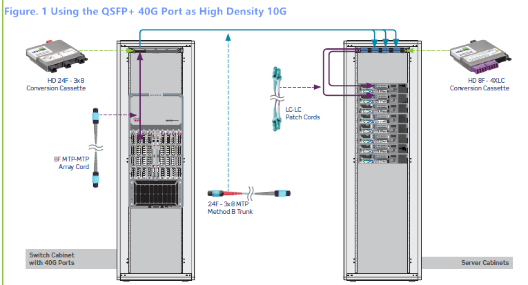
Note: in this architecture, if you have existing 12-fiber MTP trunks, you can use a cassette with two 12-fiber MTP inputs that breakout into 3×8-fiber MTP strands, instead of deploying a new 24-fiber MTP trunk cable. However, if you have to move to denser and more complicated applications, the 24-fiber MTP solution makes for easier migration.
Like the previous example, the following figure 2 also shows a similar scenario in existing 10G servers, but it uses 100Gbase-SR10 ports on the switch, which requires a 24-fiber connector to drive the 10×10 transceiver port. Instead of breaking into 8-fiber connections, it uses 24-fiber MTP fiber cable from the switch to the patch panel in the top of the rack. A 24-fiber MTP trunk connects the switch and server cabinet. The MTP cassette at the top of the server cabinet converts the 100G port into ten individual 10G port with LC connectors.
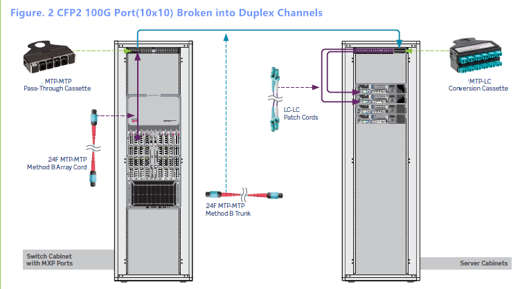
Note: As in the figure 1, in this scenario, if you already have two 12-fiber MTP trunks, you can use 12-fiber MTP adapter panel, then a 2×12-fiber to 1×24-fiber MTP harness cable could be used at the switch to build the same channel.
Figure 3 shows an example of a completely new installation, using 40G/100G right out of the box without any 10G switches in the channel. This method has 40G or 100G port on the core switches, and 40G uplinks at the ToR switches. The patch panels at the top of each rack use MTP bulkhead, with all 8-fiber cords from one QSFP port to the next.
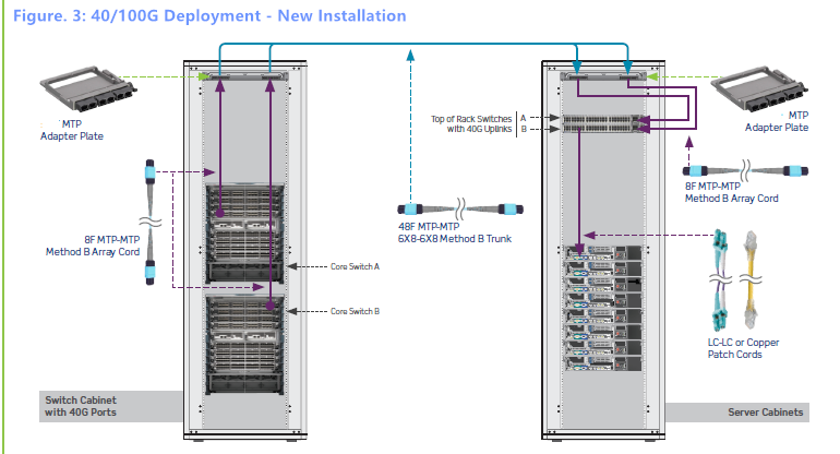
In this architecture, we can either use 24-fiber trunks that break into 40G ports, or create trunks with 8-fiber strands on every leg, with 8 fibers per 40G or 100G port, as shown in the diagram above. However, we have to pay attention that with 8-fiber legs, the density will become a challenge. In addition, 12-fiber MTP trunks are avoided in this scenario, since integrating existing 12-fiber trunks with 8-fiber connectivity on the patch cord creates fibers unused.

Deploying 10G, 40G, 100G in the same network can effectively avoid costly upgrades that require ripping out cabling and starting over with a new network architecture. This post have provided three solutions. All the devices in these three scenarios can be purchased in FS.COM. If you are interested, kindly visit FS.COM.