What is the OSI Model?
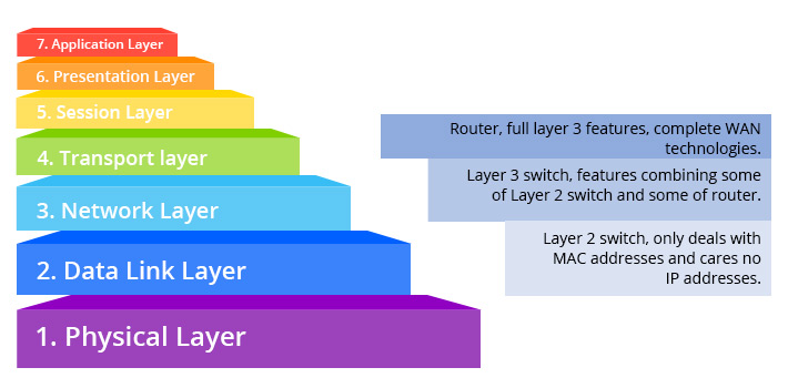
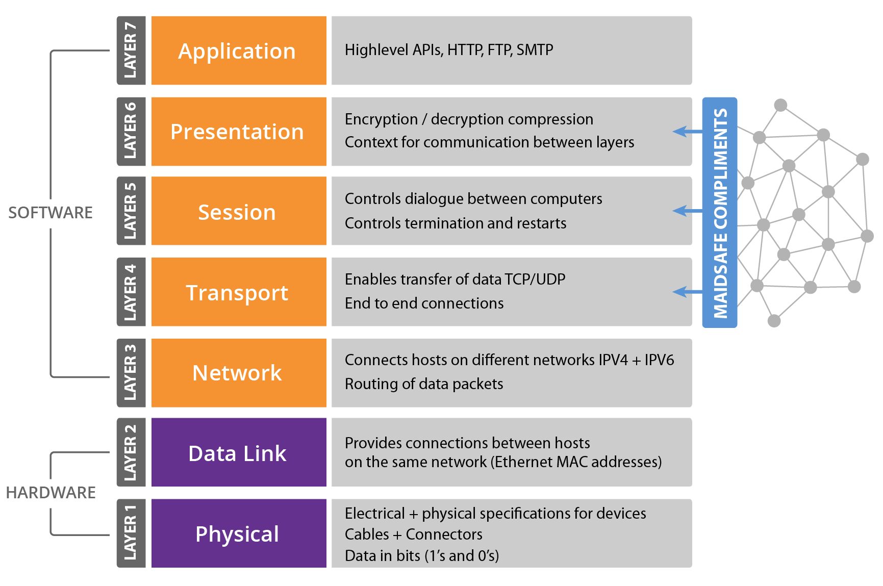
Before delving into the specifics of a Layer 3 switch, it’s essential to grasp the OSI model. The OSI (Open Systems Interconnection) model serves as a conceptual framework that standardizes the functions of a telecommunication or computing system, providing a systematic approach to understanding and designing network architecture. Comprising seven layers, the OSI model delineates specific tasks and responsibilities for each layer, from the physical layer responsible for hardware transmission to the application layer handling user interfaces. The layers are, from bottom to top:
- Layer 1 (Physical)
- Layer 2 (Data-Link)
- Layer 3 (Network)
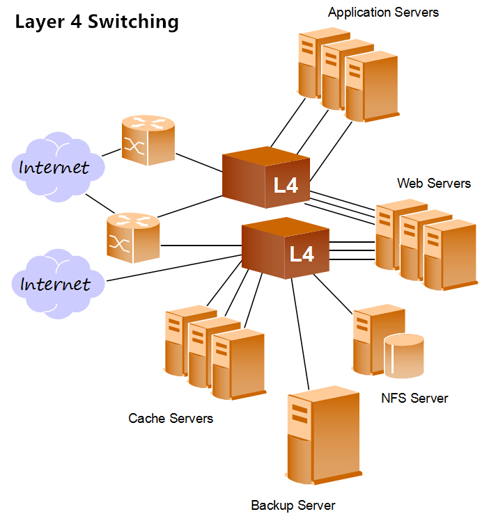
- Layer 4 (Transport)
- Layer 5 (Session)
- Layer 6 (Presentation)
- Layer 7 (Application)
What is a Layer 3 Switch?
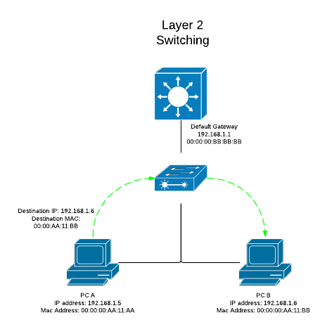
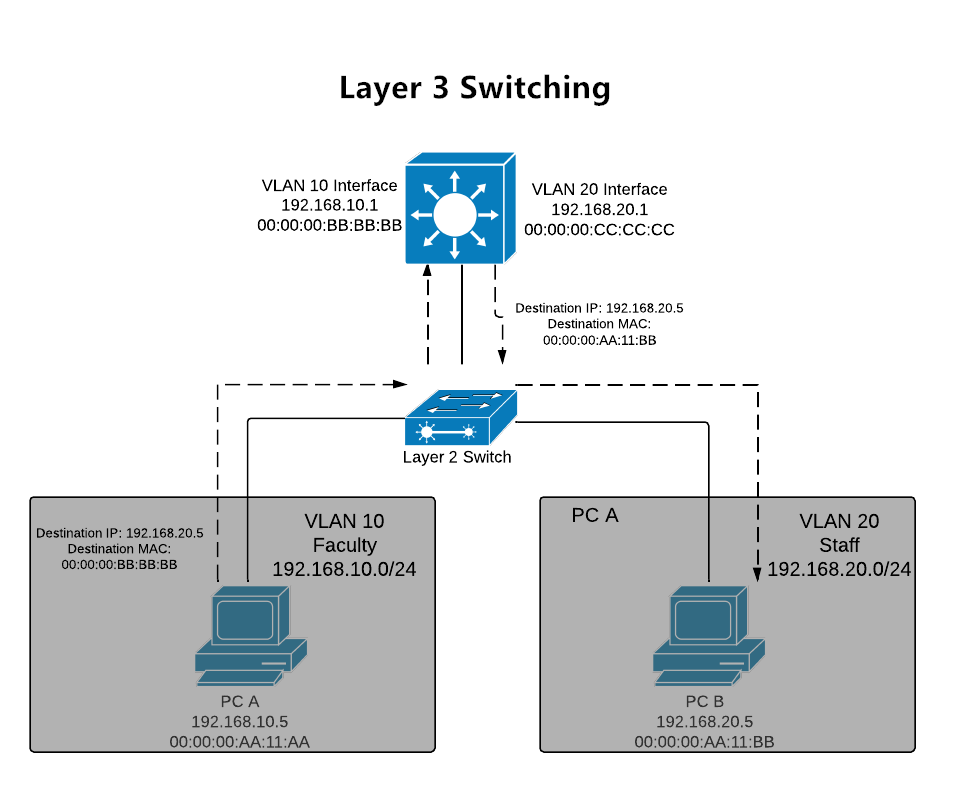
A Layer 3 switch operates at the third layer of the OSI model, known as the network layer. This layer is responsible for logical addressing, routing, and forwarding of data between different subnets. Unlike a traditional Layer 2 switch that operates at the data link layer and uses MAC addresses for forwarding decisions, a Layer 3 switch can make routing decisions based on IP addresses.
In essence, a Layer 3 switch combines the features of a traditional switch and a router. It possesses the high-speed, hardware-based switching capabilities of Layer 2 switches, while also having the intelligence to route traffic based on IP addresses.
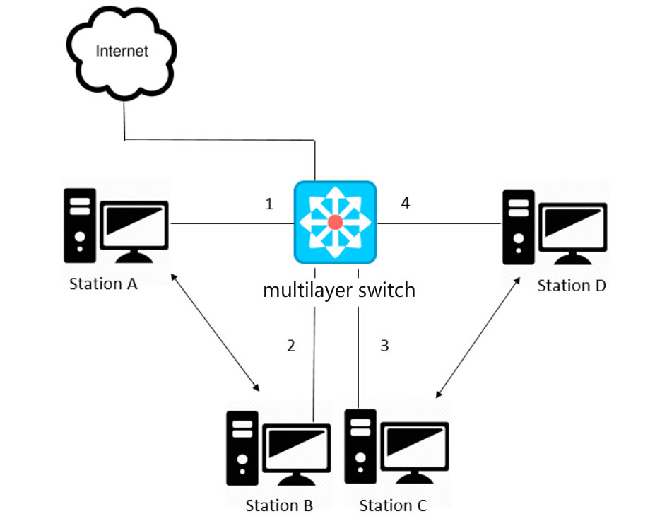
How does a Layer 3 Switch Work?
The operation of a Layer 3 switch involves both Layer 2 switching and Layer 3 routing functionalities. When a packet enters the Layer 3 switch, it examines the destination IP address and makes a routing decision. If the destination is within the same subnet, the switch performs Layer 2 switching, forwarding the packet based on the MAC address. If the destination is in a different subnet, the Layer 3 switch routes the packet to the appropriate subnet.
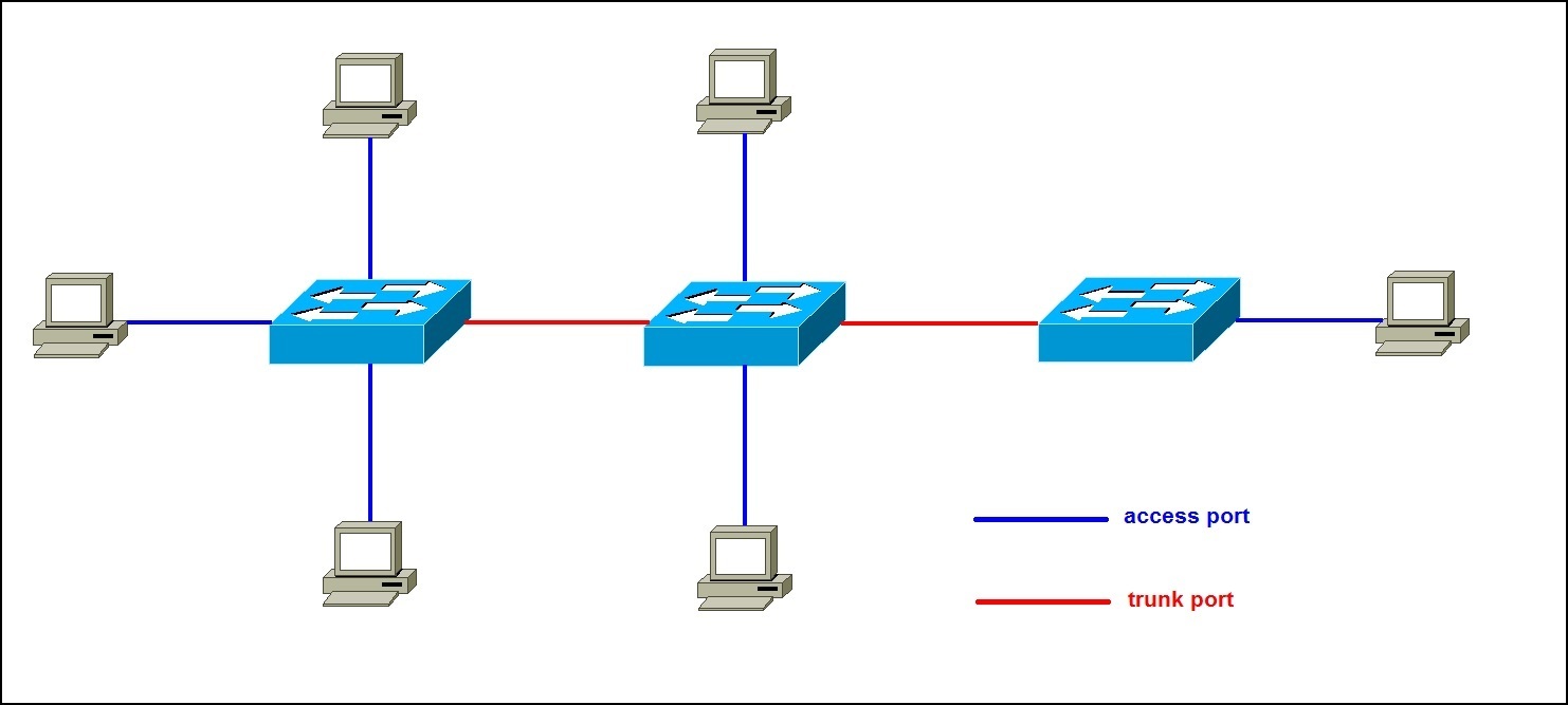
This dynamic capability allows Layer 3 switches to efficiently handle inter-VLAN routing, making them valuable in networks with multiple subnets. Additionally, Layer 3 switches often support routing protocols such as OSPF or EIGRP, enabling dynamic routing updates and adaptability to changes in the network topology.
What are the Benefits of a Layer 3 Switch?
The adoption of Layer 3 switches brings several advantages to a network:
- Improved Performance: By offloading inter-VLAN routing from routers to Layer 3 switches, network performance is enhanced. The switch’s hardware-based routing is generally faster than software-based routing on traditional routers.
- Reduced Network Traffic: Layer 3 switches can segment a network into multiple subnets, reducing broadcast traffic and enhancing overall network efficiency.
- Scalability: As businesses grow, the need for scalability becomes crucial. Layer 3 switches facilitate the creation of additional subnets, supporting the expansion of the network infrastructure.
- Cost Savings: Consolidating routing and switching functions into a single device can lead to cost savings in terms of hardware and maintenance.
Are there Drawbacks?
While Layer 3 switches offer numerous advantages, it’s important to consider potential drawbacks:
- Cost: Layer 3 switches can be more expensive than their Layer 2 counterparts, which may impact budget considerations.
- Complexity: Implementing and managing Layer 3 switches requires a certain level of expertise. The increased functionality can lead to a steeper learning curve for network administrators.
- Limited WAN Capabilities: Layer 3 switches are primarily designed for local area network (LAN) environments and may not offer the same advanced wide area network (WAN) features as dedicated routers.
Do You Need a Layer 3 Switch?
Determining whether your network needs a Layer 3 switch depends on various factors, including the size and complexity of your infrastructure, performance requirements, and budget constraints. Small to medium-sized businesses with expanding network needs may find value in deploying Layer 3 switches to optimize their operations. Larger enterprises with intricate network architectures may require a combination of Layer 2 and Layer 3 devices for a well-rounded solution.
Why Your Network Might Need One?
As organizations grow and diversify, the demand for efficient data routing and inter-VLAN communication becomes paramount. A Layer 3 switch addresses these challenges by integrating the capabilities of traditional Layer 2 switches and routers, offering a solution that not only optimizes network performance through hardware-based routing but also streamlines inter-VLAN routing within the switch itself. This not only reduces the reliance on external routers but also enhances the speed and responsiveness of the network.
Additionally, the ability to segment the network into multiple subnets provides a scalable and flexible solution for accommodating growth, ensuring that the network infrastructure remains adaptable to evolving business requirements.
Ultimately, the deployment of a Layer 3 switch becomes essential for organizations seeking to navigate the complexities of a growing network landscape while simultaneously improving performance and reducing operational costs.
Summary
In conclusion, a Layer 3 switch serves as a versatile solution for modern network infrastructures, offering a balance between the high-speed switching capabilities of Layer 2 switches and the routing intelligence of traditional routers. Understanding its role in the OSI model, how it operates, and the benefits it brings can empower network administrators to make informed decisions about their network architecture. While there are potential drawbacks, the advantages of improved performance, reduced network traffic, scalability, and cost savings make Layer 3 switches a valuable asset in optimizing network efficiency and functionality.