How 400G Ethernet Influences Enterprise Networks?

Since the approval of its relevant 802.3bs standard from the IEEE in 2017, 400GbE Ethernet has become the talk of the town. The main reason behind it is the ability of this technology to beat the existing solutions by a mile. With its implementation, the current data transfer speeds will simply see a fourfold increase. Vigorous efforts are being made by the cloud service providers and network infrastructure vendors to pace up the deployment. However, there are a number of challenges that can hamper its effective implementation and hence, the adoption.

In this article, we will have a detailed look into the opportunities and the challenges linked to the successful implementation of 400G Ethernet enterprise network. This will provide a clear picture of the impact this technology will have on large-scale organizations.

Opportunities for 400G Ethernet Enterprise Networks

  • Better management of the traffic over video streaming services
  • Facilitates IoT device requirements
  • Improved data transmission density

How can 400G Ethernet assist enterprise networks in handling growing traffic demands?

Rise of 5G connectivity

Rising traffic and bandwidth demands are compelling the CSPs for rapid adoption of 5G both at the business as well as the customer end. A successful implementation requires a massive increase in bandwidth to cater for the 5G backhaul. In addition, 400G can provide CSPs with a greater density in small cells development. 5G deployment requires the cloud data centers to be brought closer to the users as well as the devices. This streamlines the edge computing (handling time-sensitive data) part, which is another game-changer in this area.5G

Data Centers Handling Video Streaming Services Traffic

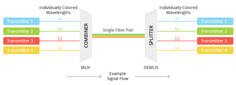
The introduction of 400GbE Ethernet has brought a great opportunity for the data centers working behind the video streaming services as Content Delivery Networks. This is because the growing demand for bandwidth is going out of hand using the current technology. As the number of users increased, the introduction of better quality streams like HD and 4K has put additional pressure on the data consumption. Therefore, the successful implementation of 400GbE would come as a sigh of relief for the data centers. Apart from rapid data transferability, issues like jitter will also be brought down. Furthermore, large amounts of data transfer over a single wavelength will also bring down the maintenance cost.

High-Performance Computing (HPC)

The application of high-performance computing is in every industry sub-vertical whether it is healthcare, retail, oil & gas or weather forecasting. Real-time analysis of data is required in each of these fields and it is going to be a driver for the 400G growth. The combined power of HPC and 400G will bring out every bit of performance from the infrastructure leading to financial and operational efficiency.400G Ethernet

Addressing the Internet of Things (IoT) Traffic Demands

Another opportunity that resides in this solution is for the data centers to manage IoT needs. Data generated by the IoT devices is not large; it is the aggregation of the connections that actually hurts. Working together, these devices open new pathways over internet and Ethernet networks which leads to an exponential increase in the traffic. A fourfold increase in the data transfer speed will make it considerably convenient for the relevant data centers to gain the upper hand in this race.

Greater Density for Hyperscale Data Centers

In order to meet the increasing data needs, the number of data centers is also seeing a considerable increase. A look at the relevant stats reveals that 111 new Hyperscale data centers were set up during the last two years, and 52 out of them were initiated during peak COVID times when the logistical issues were also seeing an unprecedented increase. In view of this fact, every data center coming to the fore is looking to setup 400GbE. Provision of greater density in fiber, racks, and switches via 400GbE would help them incorporate huge and complex computing and networking requirements while minimizing the ESG footprint at the same time.

Easier Said Than Done: What Are the Challenges In 400G Ethernet technology

Below are some of the challenges enterprise data centers are facing in 400G implementation.

Cost and Power Consumption

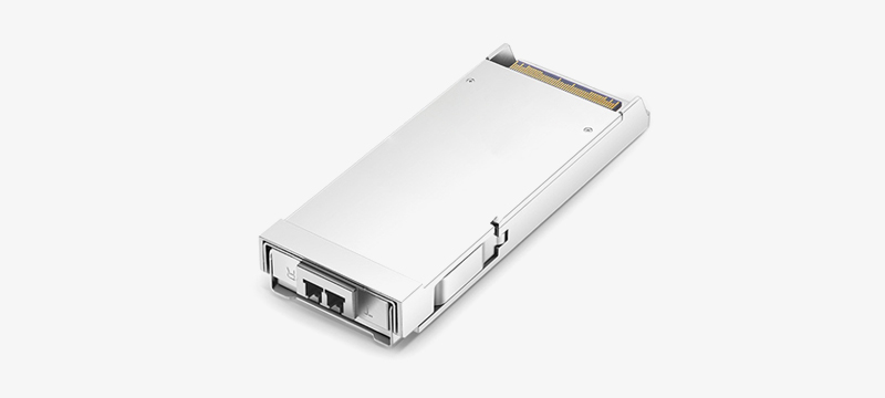
Today’s ecosystem of 400G transceivers and DSP are power-intensive. Currently, some transceivers don’t support the latest MSA. They are developed uniquely by different vendors using their proprietary technology.

Overall, the aim is to reduce $/gigabit and watts/gigabit.

The Need for Real-World Networking Plugfests

Despite the standard being approved by IEEE, a number of modifications still need to be made in various areas like specifications, manufacturing, and design. Although the conducted tests have shown promising results, the interoperability needs to be tested in real-world networking environments. This would outline how this technology is actually going to perform in enterprise networks. In addition, any issues faced at any layer of the network will be highlighted.

Transceiver Reliability

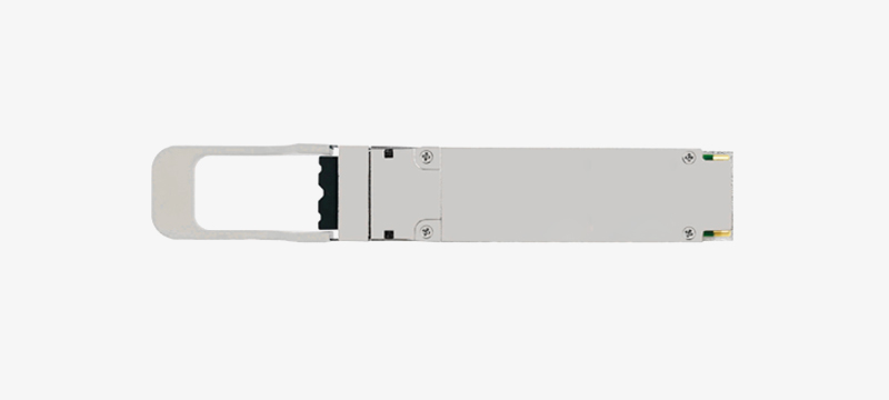
Secondly, transceiver reliability also comes as a major challenge in this regard. Currently, the relevant manufacturers are finding it hard to meet the device power budget. The main reason behind that is the use of a relatively older design of QSFP transceiver form factor as it was originally designed for 40GbE. Problems in meeting the device power budget lead to issues like heating, optical distortions, and packet loss.

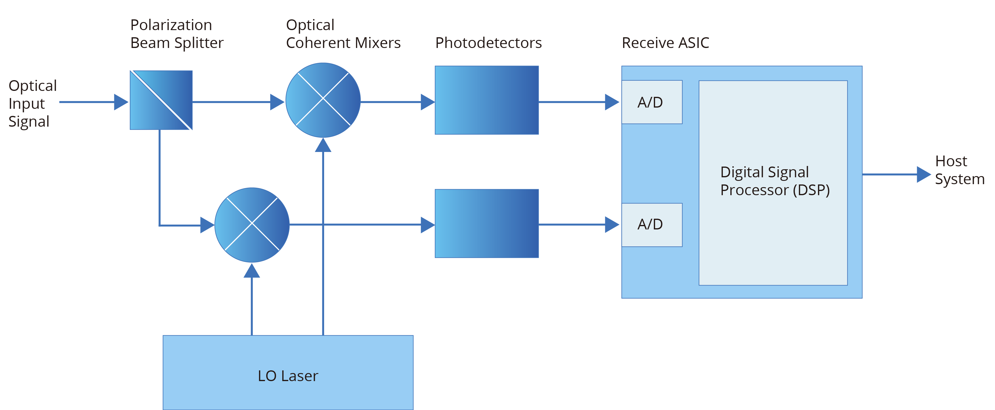
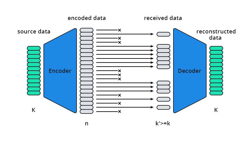
The Transition from NRZ to PAM-4

Furthermore, the shift from binary non-return to zero to pulse amplitude modulation with the introduction of 400GbE also poses a challenge for encoding and decoding. This is because NRZ was a familiar set of optical coding whereas PAM-4 requires involvement of extensive hardware and an enhanced level of sophistication. Mastering this form of coding would require time, even for a single manufacturer.from NRZ to PAM-4

Greater Risk of Link Flaps

Enterprise use of 400GbE also increases the risk of link flaps. Link flaps are defined as the phenomenon involving rapid disconnection in an optical connection. Whenever such a scenario occurs, auto-negotiation and link-training are performed before the data is allowed to flow again. While using 400GbE, link flaps can occur due to a number of additional reasons like problems with the switch, design problems with the -transceiver, or heat.

Inference

The true deployment of 400GbE Ethernet enterprise network is undoubtedly going to ease management for cloud service providers and networking vendors. However, it is still a bumpy road. With the modernization and rapid advancements in technology, scalability is going to become a lot easier for the data centers. Still, we are still a long way from the destination of a successful implementation. With higher data transfer rates easing traffic management, a lot of risks to the fiber alignment and packet loss still need to be tackled.

Article Source: How 400G Ethernet Influences Enterprise Networks?

Related Articles:

PAM4 in 400G Ethernet application and solutions

400G OTN Technologies: Single-Carrier, Dual-Carrier and Quad-Carrier

Coherent Optics and 400G Applications

In today’s high-tech and data-driven environment, network operators face an increasing demand to support the ever-rising data traffic while keeping capital and operation expenditures in check. Incremental advancements in bandwidth component technology, coherent detection, and optical networking have seen the rise of coherent interfaces that allows for efficient control, lower cost, power, and footprint.

Below, we have discussed more about 400G, coherent optics, and how the two are transforming data communication and network infrastructures in a way that’s beneficial for clients and network service providers.

What is 400G?

400G is the latest generation of cloud infrastructure, which represents a fourfold increase in the maximum data-transfer speed over the current maximum standard of 100G. Besides being faster, 400G has more fiber lanes, which allows for better throughput (the quantity of data handled at a go). Therefore, data centers are shifting to 400G infrastructure to bring new user experiences with innovative services such as augmented reality, virtual gaming, VR, etc.

Simply put, data centers are like an expressway interchange that receives and directs information to various destinations, and 400G is an advancement to the interchange that adds more lanes and a higher speed limit. This not only makes 400G the go-to cloud infrastructure but also the next big thing in optical networks.

400G

What is Coherent Optics?

Coherent optical transmission or coherent optics is a technique that uses a variation of the amplitude and phase or segment of light and transmission across two polarizations to transport significantly more information through a fiber optic cable. Coherent optics also provides faster bit rates, greater flexibility, modest photonic line systems, and advanced optical performance.

This technology forms the basis of the industry’s drive to embrace the network transfer speed of 100G and beyond while delivering terabits of data across one fiber pair. When appropriately implemented, coherent optics solve the capacity issues that network providers are experiencing. It also allows for increased scalability from 100 to 400G and beyond for every signal carrier. This delivers more data throughput at a relatively lower cost per bit.

Coherent

Fundamentals of Coherent Optics Communication

Before we look at the main properties of coherent optics communication, let’s first understand the brief development of this data transmission technique. Ideally, fiber-optic systems came to market in the mid-1970s, and enormous progress has been realized since then. Subsequent technologies that followed sought to solve some of the major communication problems witnessed at the time, such as dispersion issues and high optical fiber losses.

And though coherent optical communication using heterodyne detection was proposed in 1970, it did not become popular because the IMDD scheme dominated the optical fiber communication systems. Fast-forward to the early 2000s, and the fifth-generation optical systems entered the market with one major focus – to make the WDM system spectrally efficient. This saw further advances through 2005, bringing to light digital-coherent technology & space-division multiplexing.

Now that you know a bit about the development of coherent optical technology, here are some of the critical attributes of this data transmission technology.

  • High-grain soft-decision FEC (forward error correction):This enables data/signals to traverse longer distances without the need for several subsequent regenerator points. The results are more margin, less equipment, simpler photonic lines, and reduced costs.
  • Strong mitigation to dispersion: Coherent processors accounts for dispersion effects once the signals have been transmitted across the fiber. The advanced digital signal processors also help avoid the headaches of planning dispersion maps & budgeting for polarization mode dispersion (PMD).
  • Programmability: This means the technology can be adjusted to suit a wide range of networks and applications. It also implies that one card can support different baud rates or multiple modulation formats, allowing operators to choose from various line rates.

The Rise of High-Performance 400G Coherent Pluggables

With 400G applications, two streams of pluggable coherent optics are emerging. The first is a CFP2-based solution with 1000+km reach capability, while the second is a QSFP DD ZR solution for Ethernet and DCI applications. These two streams come with measurement and test challenges in meeting rigorous technical specifications and guaranteeing painless integration and placement in an open network ecosystem.

When testing these 400G coherent optical transceivers and their sub-components, there’s a need to use test equipment capable of producing clean signals and analyzing them. The test equipment’s measurement bandwidth should also be more than 40-GHz. For dual-polarization in-phase and quadrature (IQ) signals, the stimulus and analysis sides need varying pulse shapes and modulation schemes on the four synchronized channels. This is achieved using instruments that are based on high-speed DAC (digital to analog converters) and ADC (analog to digital converters). Increasing test efficiency requires modern tools that provide an inclusive set of procedures, including interfaces that can work with automated algorithms.

Coherent Optics Interfaces and 400G Architectures

Supporting transport optics in form factors similar to client optics is crucial for network operators because it allows for simpler and cost-effective architectures. The recent industry trends toward open line systems also mean these transport optics can be plugged directly into the router without requiring an external transmission system.

Some network operators are also adopting 400G architectures, and with standardized, interoperable coherent interfaces, more deployments and use cases are coming to light. Beyond DCI, several application standards, such as Open ROADM and OpenZR+, now offer network operators increased performance and functionality without sacrificing interoperability between modules.

Article Source:Coherent Optics and 400G Applications

Related Articles:
Typical Scenarios for 400G Network: A Detailed Look into the Application Scenarios
How 400G Ethernet Influences Enterprise Networks?
ROADM for 400G WDM Transmission

400G Multimode Fiber: 400G SR4.2 vs 400G SR8

Cloud and AI applications are driving demand for data rates beyond 100 Gb/s, moving to high-speed and low-power 400 Gb/s interconnects. The optical fiber industry is responding by developing two IEEE 400G Ethernet standards, namely 400GBASE-SR4.2 and 400GBASE-SR8, to support the short-reach application space inside the data center. This article will elaborate on the two standards and their comparison.

400GBASE-SR4.2

400GBASE-SR4.2, also called 400GBASE-BD4.2, is a 4-pair, 2-wavelength multimode solution that supports reaches of 70m (OM3), 100m (OM4), and 150m (OM5). It is not only the first instance of an IEEE 802.3 solution that employs both multiple pairs of fibers and multiple wavelengths, but also the first Ethernet standard to use two short wavelengths to double multimode fiber capacity from 50 Gb/s to 100 Gb/s per fiber.

400GBASE-SR4.2 operates over the same type of cabling used to support 40GBASE-SR4, 100GBASE-SR4 and 200GBASE-SR4. It uses bidirectional transmission on each fiber, with each wavelength traveling in opposite directions. As such, each active position at the transceiver is both a transmitter and a receiver, which means 400GBASE-SR4.2 has eight optical transmitters and eight optical receivers in a bidirectional optical configuration.

The optical lane arrangement is shown as follows. The leftmost four positions labeled TR transmit wavelength λ1 (850nm) and receive wavelength λ2 (910nm). Conversely, the rightmost four positions labeled RT receive wavelength λ1 and transmit wavelength λ2.

400GBASE-SR4.2 fiber interface

400GBASE-SR8

400GBASE-SR8 is an 8-pair, 1-wavelength multimode solution that supports reaches of 70m (OM3), 100m (OM4 & OM5). It is the first IEEE fiber interface to use eight pairs of fibers. Unlike 400GBASE-SR4.2, it operates over a single wavelength (850nm) with each pair supporting 50 Gb/s transmission. In addition, it has two variants of optical lane arrangement. One variant uses the 24-fiber MPO, configured as two rows of 12 fibers, and the other interface variant uses a single-row MPO-16.

400GBASE-SR8 fiber interface variant 1
400GBASE-SR8 fiber interface variant 2

400GBASE-SR8 offers flexibility of fiber shuffling with 50G/100G/200G configurations. It also supports breakout at different speeds for various applications such as compute, storage, flash, GPU, and TPU. 400G-SR8 QSFP DD/OSFP transceivers can be used as 400GBASE-SR8, 2x200GBASE-SR4, 4x100GBASE-SR2, 8x50GBASE-SR.

400G SR4.2 vs. 400G SR8

As multimode solutions for 400G Ethernet, 400GBASE-SR4.2 and 400GBASE-SR8 share some features, but they also differ in a number of ways as discussed in the previous section.

The following table shows a clear picture of how they compare to each other.

 400GBASE-SR4.2400GBASE-SR8
AllianceIEEE 802.3cmIEEE 802.3cm (breakout: 802.3cd)
Max reach150m over OM5100m over OM4/OM5
Fibers8 fibers16 fibers (ribbon patch cord)
Wavelength2 wavelengths (850nm and 910nm)1 wavelength (850nm)
BiDi technologySupport/
Signal modulation formatPAM4 signalingPAM4 signaling
LaserVCSELVCSEL
Form factorQSFP-DD, OSFPQSFP-DD, OSFP

400GBASE-SR8 is technically simple but requires a ribbon patch cord with 16 fibers. It is usually built with 8 VCSEL lasers and doesn’t include any gearbox, so the overall cost of modules and fibers remains low. By contrast, 400GBASE-SR4.2 is technically more complex so the overall cost of related fibers or modules is higher, but it can support a longer reach.

In addition, 400GBASE-SR8 offers both flexibility and higher density. It supports fiber shuffling with 50G/100G/200G configurations and fanout at different I/O speeds for various applications. A 400G-SR8 QSFP-DD transceiver can be used as 400GBASE-SR8, 2x200GBASE-SR4, 4x100GBASE-SR2, or 8x50GBASE-SR.

400G SR4.2 & 400G SR8: Boosting Higher Speed Ethernet

As multimode fiber continues to evolve to serve growing demands for speed and capacity, both 400GBASE-SR4.2 and 400GBASE-SR8 help boost 400G Ethernet and scale up multimode fiber links too ensure the viability of optical solutions for various demanding applications.

The two IEEE 802.3cm standards provide a smooth evolution path for Ethernet, boosting cloud-based services and applications. Future advances point toward the ability to support even higher data rates as they are upgraded to the next level. The data center Industry will take advantage of the latest multimode fiber technology such as OM5 fiber, and use multiple wavelengths to transmit 100 Gb/s and 400 Gb/s over fibers over short reach of more than150 meters.

Beyond 2021-2022 timeframe, once an 800 Gb/s Ethernet standard is standardized, using more advanced technology with two-wavelength operation could create an 800 Gb/s, four-pair link. At the same time a single wavelength could support an 800 Gb/s eight-pair link. In this sense, 400GBASE-SR4.2 and 400GBASE-SR8 are setting the pace for a promising future.

Article Source: 400G Multimode Fiber: 400G SR4.2 vs 400G SR8

Related Articles:

400G Modules: Comparing 400GBASE-LR8 and 400GBASE-LR4
400G Optics in Hyperscale Data Centers
How 400G Has Transformed Data Centers

Importance of FEC for 400G


The rapid adoption of 400G technologies has seen a spike in bandwidth demands and a low tolerance for errors and latency in data transmission. Data centers are now rethinking the design of data communication systems to expand the available bandwidth while improving transmission quality.

Meeting this goal can be quite challenging, considering that improving one aspect of data transmission consequently hurts another. However, one solution seems to stand out from the rest as far as enabling reliable, efficient, and high-quality data transmission is concerned. We’ve discussed more on Forward Error Correction (FEC) and 400G technology in the sections below, including the FEC considerations for 400Gbps Ethernet.

What Is FEC?

Forward Error Correction is an error rectification method used in digital signals to improve data reliability. The technique is used to detect and correct errors in data being transmitted without retransmitting the data.

FEC introduces redundant data and the error-correcting code before data transmission is done. The redundant bits/data are complex functions of the original information and are sent multiple times since an error can appear in any transmitted samples. The receiver then corrects errors without requesting retransmission of the data by acknowledging only parts of the data with no apparent errors.

FEC codes can also generate bit-error-rate signals used as feedback to fine-tune analog receiving electronics. The FEC code design determines the number of missing bits that can be corrected. Block codes and convolutional codes are the two FEC code categories that are widely used. Convolutional codes handle arbitrary-length data and use the Viterbi algorithm for decoding purposes. On the other hand, block codes handle fixed-size data packets, and partial code blocks are decoded in polynomial time to the code block length.

FEC

What Is 400G?

This is the next generation of cloud infrastructure widely used by high-traffic volume data centers, telecommunication service providers, and other large enterprises with relentless data transmission needs. The rapidly increasing network traffic has seen network carriers continually face bandwidth challenges. This exponential sprout in traffic is driven by the increased deployments of machine learning, cloud computing, artificial intelligence (AI), and IoT devices.

Compared to the previous 100G solution, 400G, also known as 400GbE or 400GB/s, is four times faster. This Terabit Ethernet transmits data at 400 billion bits per second, i.e., in optical wavelength; hence it’s finding application in high-speed, high-performance deployments.

The 400G technology also delivers the power, data density, and efficiency required for cutting-edge technologies such as virtual reality (VR), augmented reality (AR), 5G, and 4K video streaming. Besides consuming less power, the speeds also support scale-out and scale-up architectures by providing high density, low-cost-per-bit, and reliable throughput.

Why 400G Requires FEC

Several data centers are adopting 400 Gigabit Ethernet, thanks to the faster network speeds and expanded use cases that allow for new business opportunities. This 400GE data transmission standard uses the PAM4 technology, which offers twice the transmission speed of NRZ technology used for 100GE.

The increased speed and convenience of PAM4 also come with its own challenges. For instance, the PAM4 transmission speed is twice as fast as that of NRZ, but the signal levels are half that of 100G technology. This degrades the signal-to-noise ratio (SNR); hence 400G transmissions are more susceptible to distortion.

Therefore, forward error correction (FEC) is used to solve the waveform distortion challenge common with 400GE transmission. That said, the actual transmission rate of a 400G Ethernet link is 425Gbps, with the additional 25 bits used in establishing the FEC techniques. 400GE elements, such as DR4 and FR4 optics, have transmission errors, which FEC helps rectify.

FEC Considerations for 400Gbps Ethernet

With the 802.3bj standards, FEC-related latency is often targeted to be equal to or less than 100ns. Here, the receive time for FEC-frame takes approximately 50ns, with the rest time budget used for decoding. This FEC latency target is practical and achievable.

Using similar/same FEC code for the 400GbE transmission makes it possible to achieve lower latency. But when a higher coding gain FEC is required, e.g., at the PMD level, one can trade off FEC latency for the desired coding gain. It’s therefore recommended to keep a similar latency target (preferably 100ns) while pushing for a higher coding gain of FEC.

Given that PAM4 modulation is used, FEC’s target coding gain (CG) could be over 8dB. And since soft-decision FEC comes with excessive power consumption, it’s not often preferred for 400GE deployments. Similarly, conventional block codes with their limited latency need a higher overclocking ratio to achieve the target.

Assuming that a transcoding scheme similar to that used in 802.3bj is included, the overclocking ratio should be less than 10%. This helps minimize the line rate increase while ensuring sufficient coding gain with limited latency.

So under 100ns latency and less than 10% overclocking ratio, FEC codes with about 8.5dB coding gain are realizable for 400GE transmission. Similarly, you can employ M (i.e., M>1) independent encoders for M-interleaved block codes instead of using parallel encoders to achieve 400G throughput.

Conclusion

400GE transmission offers several benefits to data centers and large enterprises that rely on high-speed data transmission for efficient operation. And while this 400G technology is highly reliable, it introduces some transmission errors that can be solved effectively using forward error correction techniques. There are also some FEC considerations for 400G Ethernet, most of which rely on your unique data transmission and network needs.


Article Source: Importance of FEC for 400G

Related Articles:
How 400G Ethernet Influences Enterprise Networks?
How Is 5G Pushing the 400G Network Transformation?
400G Transceiver, DAC, or AOC: How to Choose?

ROADM for 400G WDM Transmission

As global optical networks advance, there is an increasing necessity for new technologies such as 400G that meet the demands of network operators. Video streaming, surging data volumes, 5G network, remote working, and ever-growing business necessities create extreme bandwidth demands.

Network operators and data centers are also embracing WDM transmission to boost data transfer speed, increase bandwidth and enhance a better user experience. And to solve some of the common 400G WDM transmission problems, such as reduced transmission reach, ROADMs are being deployed. Below, we have discussed more about ROADM for 400G WDM transmission.

Reconfigurable Optical Add-drop Multiplexer (ROADM) Technology

ROADM is a device with access to all wavelengths on a fiber line. Introduced in the early 2000s, ROADM allows for remote configuration/reconfiguration of A-Z lightpaths. Its networking standard makes it possible to block, add, redirect or pass visible light beams and modulated infrared (IR) in the fiber-optic network depending on the particular wavelength.

ROADMs are employed in systems that utilize wavelength division multiplexing (WDM). It also supports more than two directions at sites for optical mesh-based networking. Unlike its predecessor, the OADM, ROADM can adjust the add/drop vs. pass-through configuration whenever traffic patterns change.

As a result, the operations are simplified by automating the connections through an intermediate site. This implies that it’s unnecessary to deploy technicians to perform manual patches in response to a new wavelength or alter a wavelength’s path. The results are optimized network traffic where bandwidth demands are met without incurring extra costs.

ROADM

Overview of Open ROADM

Open ROADM is a 400G pluggable solution that champions cross-vendor interoperability for optical equipment, including ROADMs, transponders, and pluggable optics. This solution defines some optical interoperability requirements for ROADM and comprises hardware devices that manage and routes traffic over the fiber optic lines.

Initially, Open ROADM was designed to address the rise in data traffic on wireless networks experienced between 2007 and 2015. The major components of Open ROADM – ROADM switch, pluggable optics, and transponder – are controllable via an open standards-based API accessible through an SDN Controller.

One of the main objectives of Open ROADM is to ensure network operators and vendors devise a universal approach to designing networks that are flexible, scalable, and cost-effective. It also offers a standard model to streamline the management of multi-vendor optical network infrastructure.

400G and WDM Transmission

WDM transmission is a multiplexing technique of several optical carrier signals through a single optical fiber channel by varying the wavelength of the laser lights. This technology allows different data streams to travel in both directions over a fiber network, increasing bandwidth and reducing the number of fibers used in the primary network or transmission line.

With 400G technology seeing widespread adoption in various industries, there’s a need for optical fiber networking systems to adapt and support the increasing data speeds and capacity. WDM transmission technique offers this convenience and is considered a technology of choice for transmitting larger amounts of data across networks/sites. WDM-based networks can also hold various data traffic at different speeds over an optical channel, allowing for increased flexibility.

400G WDM still faces a number of challenges. For instance, the high symbol rate stresses the DAC/ADC in terms of bandwidth, while the high-order quadrature amplitude modulation (QAM) stresses the DAC/ADC in terms of its ENOB (effective number of bits.)

As far as transmission performance is concerned, the high-order QAM requires more optical signal-to-noise ratio (OSNR) at the receiver side, which reduces the transmission reach. Additionally, it’s more sensitive to the accumulation of linear and non-linear phase noise. Most of these constraints can be solved with the use of ROADM architectures. We’ve discussed more below.

WDM Transmission

Open ROADM MSA and the ROADM Architecture for 400G WDM

The Open ROADM MSA defines some interoperability specifications for ROADM switches, pluggable optics, and transponders. Most ROADMs in the market are proprietary devices built by specific suppliers making interoperability a bit challenging. The Open ROADM MSA, therefore, seeks to provide the technical foundation to deploy networks with increased flexibility.

In other words, Open ROADM aims at disaggregating the data network by allowing for the coexistence of multiple transponders and ROADM vendors with a few restrictions. This can be quite helpful for 400G WDM systems, especially when lead-time and inventory issues arise, as the ability to mix & match can help eliminate delays.

By leveraging WDM for fiber gain as well as optical line systems with ROADMs, network operators can design virtual fiber paths between two points over some complex fiber topologies. That is, ROADMs introduce a logical transport underlay of single-hop router connections that can be optimized to suit the IP traffic topology. These aspects play a critical role in enhancing 400G adoption that offers the much-needed capacity-reach, flexibility, and efficiency for network operators.

That said, ROADMs have evolved over the years to support flexile-grid WSS technology. One of the basic ROADM architectures uses fixed filters for add/drop, while the other architectures offer flexibility in wavelength assignment/color or the option to freely route wavelengths in any direction with little to no restriction. This means you can implement multi-degree networking with multiple fiber paths for every node connecting to different sites. The benefit is that you can move traffic along another path if one fiber path isn’t working.

Conclusion

As data centers and network operators work on minimizing overall IP-optical network cost, there’s a push to implement robust, flexible, and optimized IP topologies. So by utilizing 400GbE client interfaces, ROADMs for 400G can satisfy the ever-growing volume requirements of DCI and cloud operators. Similarly, deploying pluggable modules and tapping into the WDM transmission technique increases network capacity and significantly reduces power consumption while simplifying maintenance and support.

Article Source: ROADM for 400G WDM Transmission
Related Articles:

400G ZR vs. Open ROADM vs. ZR+
FS 200G/400G CFP2-DCO Transceivers Overview

FS 400G Product Family Introduction

400G ZR vs. Open ROADM vs. ZR+


As global optical networks evolve, there’s an increasing need to innovate new solutions that meet the requirements of network operators. Some of these requirements include the push to maximize fiber utilization while reducing the cost of data transmission. Over the last decade, coherent optical transmission has played a critical role in meeting these requirements, and it’s expected to progressively improve for the next stages of tech and network evolution.

Today, we have coherent pluggable solutions supporting data rates from 100G to 400G. These performance-optimized systems are designed for small spaces and are low power, making them highly attractive to data center operators. We’ve discussed the 400G ZR, Open ROADM, and ZR+ optical networking standards below.

Understanding 400G ZR vs. Open ROADM vs. ZR+

Depending on the network setups and the unique data transmission requirements, data centers can choose to deploy any of the coherent pluggable solutions. We’ve highlighted key facts about these solutions below, from definitions to differences and applications.

What Is 400G ZR?

400G ZR defines a classic, economical, and interoperable standard for transferring 400 Gigabit Ethernet over a single optical wavelength using DWDM (dense wavelength division multiplexing) and higher-order modulation such as 16 QAM. The Optical Interoperability Forum (OIF) developed this low-cost standard for data transmission as one of the first standards to define an interoperable 400G interface.

400G ZR leverages an ultra-modern coherent optical technology and supports high-capacity point-to-point data transport over DCI links between 80 and 120km. The performance of 400ZR modules is also limited to ensure it’s cost-effective with a small physical size. This helps ensure that the power consumption fits within smaller modules such as the Quad Small Form-Factor Pluggable Double-Density (QSFP-DD) and Octal-Small Form-Factor Pluggable (OSFP). The 400G ZR enables the use of inexpensive yet modest performance components within the modules.

400G ZR

What Is Open ROADM?

This is one of the 400G pluggable solutions that define interoperability specifications for Reconfigurable Optical Add/Drop Multiplexers (ROADM). The latter comprises hardware devices that manage and route data traffic transported over high-capacity fiber-optic lines. Open ROADM was first designed to combat the surge in traffic on the wireless network experienced between the years 2007 and 2015.

The key components of Open ROADM include ROADM switch, transponders, and pluggable optics – all controllable via open standards-based API accessed via an SDN Controller utilizing the NETCONF protocol. Launched in 2016, the Open ROADM initiative’s main objective was to bring together multiple vendors and network operators so they could devise an agreed approach to design networks that are scalable, cost-effective, and flexible.

This multi-source agreement (MSA) aims to shift from a traditionally closed ROADM optical transport network toward a disaggregated open transport network while allowing for centralized software control. Some of the ways to disaggregate ROADM systems include hardware disaggregation (e.g., defining a common shelf) and functional disaggregation (less about hardware, more about function).

The Open ROADM MSA went for the functional disaggregation first because of the complexity of common shelves. The team intended to focus on simplicity, concentrating on lower-performance metro systems at the time of its first release. Open ROADM handles 100-400GbE and 100-400G OTN client traffic within a typical deployment paradigm of 500km.

Open ROADM

What Is ZR+?

The ZR+ represents a series of coherent pluggable solutions holding line capacities up to 400 Gb/s and stretching well past the 120km specification for 400ZR. OpenZR+ was designed to maintain the classic Ethernet-only host interface of 400ZR while adding support to aid features such as the extended point-to-point reach of up to around 500km and the inclusion of support for OTN Ethernet, etc.

The recently issued MSA provides interoperable 100G, 200G, 300G & 400G line rates over regional, metro, and long-haul distances, utilizing OpenFEC forward error correction and 100-400G optical line specifications. There’s also a broad range of coverage for ZR+ pluggable, and these products can be deployed across routers, switches, and optical transport equipment.

ZR+

400G ZR, Open ROADM, and ZR+ Differences

Target Application

400ZR and OpenZR+ were designed to satisfy the growing volume requirements of DCI and cloud operators using 100GbE/400GbE client interfaces, while OpenROADM provides a good alternative for carriers that require transporting OTN client signals (OTU4).

In other words, the 400ZR efforts concentrate on one modulation type and line rate (400G) for metro point-to-point applications. On the other hand, the OpenZR+ and Open ROADM groups concentrate on high-efficiency optical specifications capable of adjustable 100G-400G line rates and lengthier optical reaches.

400G Reach: Deployment Paradigm

400ZR modules support high-capacity data transport over DCI links of up to 80 to 120km. On the other hand, OpenZR+ and OpenROADM, under perfect network presumption, can transmit the network for up to 480 km in 400G mode.

Power Targets

The power consumption targets of these coherent pluggable also vary. For instance, the 400zr has a target power consumption of 15W, while Open ROADM and ZR+ have power consumption targets of not more than 25W.

Applications for 400G ZR, Open ROADM and ZR+

Each of these coherent pluggable solutions finds use cases in various settings. Below is a quick summary of the three data transfer standards and their major applications.

  • 400G ZR – frequently used for point-to-point DCI (up to 80km), simplifying the task of interconnecting data centers.
  • Open ROADM – This architecture can be deployed using different vendors, provided they exist in the same network. It gives the option to use transponders from various vendors at the end of each circuit.
  • ZR+ – It provides a comprehensive, open, and flexible coherent solution in a relatively smaller form factor pluggable module. This standard addresses hyperscale data center applications for high-intensive edge and regional interconnects.

A Look into the Future

As digital transformation takes shape across industries, there’s an increasing demand for scalable solutions and architectures for transmitting and accessing data. The industry is also moving towards real-world deployments of 400G networks, and the three coherent pluggable solutions above are seeing wider adoption.

400ZR and the OpenZR+ specifications were developed to meet the network demands of DCI and cloud operators using 100 and 400GbE interfaces. On the other hand, Open ROADM offers a better alternative for carriers that want to transport OTN client signals. Currently, Open ZR+ and Open ROADM provide more benefits to data center operators than 400G ZR, and technology is just getting better. Moving into the future, optical networking standards will continue to improve both in design and performance.

Article Source: 400G ZR vs. Open ROADM vs. ZR+
Related Articles:

ROADM for 400G WDM Transmission

400G ZR & ZR+ – New Generation of Solutions for Longer-reach Optical Communications

FS 400G Cabling Solutions: DAC, AOC, and Fiber Cabling

How Is 5G Pushing the 400G Network Transformation?

With the rapid technological disruption and the wholesale shift to digital, several organizations are now adopting 5G networks, thanks to the fast data transfer speeds and improved network reliability. The improved connectivity also means businesses can expand on their service delivery and even enhance user experiences, increasing market competitiveness and revenue generated.

Before we look at how 5G is driving the adoption of 400G transformation, let’s first understand what 5G and 400G are and how the two are related.

What is 5G?

5G is the latest wireless technology that delivers multi-Gbps peak data speeds and ultra-low latency. This technology marks a massive shift in communication with the potential to greatly transform how data is received and transferred. The increased reliability and a more consistent user experience also enable an array of new applications and use cases extending beyond network computing to include distributed computing.

And while the future of 5G is still being written, it’s already creating a wealth of opportunities for growth & innovation across industries. The fact that tech is constantly evolving and that no one knows exactly what will happen next is perhaps the fascinating aspect of 5G and its use cases. Whatever the future holds, one is likely certain: 5G will provide far more than just a speedier internet connection. It has the potential to disrupt businesses and change how customers engage and interact with products and services.

What is 400G?

400G or 400G Ethernet is the next generation of cloud infrastructure that offers a four-fold jump in max data-transfer speed from the standard maximum of 100G. This technology addresses the tremendous bandwidth demands on network infrastructure providers, partly due to the massive adoption of digital transformation initiatives.

Additionally, exponential data traffic growth driven by cloud storage, AI, and Machine Learning use cases has seen 400G become a key competitive advantage in the networking and communication world. Major data centers are also shifting to quicker, more scalable infrastructures to keep up with the ever-growing number of users, devices, and applications. Hence high-capacity connection is becoming quite critical.

How are 5G and 400G Related?

The 5G wireless technology, by default, offers greater speeds, reduced latencies, and increased data connection density. This makes it an attractive option for highly-demanding applications such as industrial IoT, smart cities, autonomous vehicles, VR, and AR. And while the 5G standard is theoretically powerful, its real-world use cases are only as good as the network architecture this wireless technology relies on.

The low-latency connections required between devices, data centers, and the cloud demands a reliable and scalable implementation of the edge-computing paradigms. This extends further to demand greater fiber densification at the edge and substantially higher data rates on the existing fiber networks. Luckily, 400G fills these networking gaps, allowing carriers, multiple-system operators (MSOs), and data center operators to streamline their operations to meet most of the 5G demands.

5G Use Cases Accelerating 400G transformation

As the demand for data-intensive services increases, organizations are beginning to see some business sense in investing in 5G and 400G technologies. Here are some of the major 5G applications driving 400G transformation.

High-Speed Video Streaming

The rapid adoption of 5G technology is expected to take the over-the-top viewing experience to a whole new level as demand for buffer-free video streaming, and high-quality content grows. Because video consumes the majority of mobile internet capacity today, the improved connectivity will give new opportunities for digital streaming companies. Video-on-demand (VOD) enthusiasts will also bid farewell to video buffering, thanks to the 5G network’s ultra-fast download speeds and super-low latency. Still, 400G Ethernet is required to ensure reliable power, efficiency, and density to support these applications.

Virtual Gaming

5G promises a more captivating future for gamers. The network’s speed enhances high-definition live streaming, and thanks to ultra-low latency, 5G gaming won’t be limited to high-end devices with a lot of processing power. In other words, high-graphics games can be displayed and controlled by a mobile device; however, processing, retrieval, and storage can all be done in the cloud.

Use cases such as low-latency Virtual Reality (VR) apps, which rely on fast feedback and near-real-time response times to give a more realistic experience, also benefit greatly from 5G. And as this wireless network becomes the standard, the quantity and sophistication of these applications are expected to peak. That is where 400G data centers and capabilities will play a critical role.

The Internet of Things (IoT)

Over the years, IoT has grown and become widely adopted across industries, from manufacturing and production to security and smart home deployments. Today, 5G and IoT are poised to allow applications that would have been unthinkable a few years ago. And while this ultra-fast wireless technology promises low latency and high network capacity to overcome the most significant barriers to IoT proliferation, the network infrastructure these applications rely on is a key determining factor. Taking 5G and IoT to the next level means solving the massive bandwidth demands while delivering high-end flexibility that gives devices near real-time ability to sense and respond.

400G Network

400G Ethernet as a Gateway to High-end Optical Networks

Continuous technological improvements and the increasing amount of data generated call for solid network infrastructures that support fast, reliable, and efficient data transfer and communication. Not long ago, 100G and 200G were considered sophisticated network upgrades, and things are getting even better.

Today, operators and service providers that were among the first to deploy 400G are already reaping big from their investments. Perhaps one of the most compelling features of 400G isn’t what it offers at the moment but rather its ability to accommodate further upgrades to 800G and beyond. What’s your take on 5G and 400G, or your progress in deploying these novel technologies?

Article Source: How Is 5G Pushing the 400G Network Transformation?

Related Articles:

Typical Scenarios for 400G Network: A Detailed Look into the Application Scenarios

What’s the Current and Future Trend of 400G Ethernet?

How 400G Has Transformed Data Centers

With the rapid technological adoption witnessed in various industries across the world, data centers are adapting on the fly to keep up with the rising client expectations. History is also pointing to a data center evolution characterized by an ever-increasing change in fiber density, bandwidth, and lane speeds.

Data centers are shifting from 100G to 400G technologies in a bid to create more powerful networks that offer enhanced experiences to clients. Some of the factors pushing for 400G deployments include recent advancements in disruptive technologies such as AI, 5G, and cloud computing.

Today, forward-looking data centers that want to maximize cost while ensuring high-end compatibility and convenience have made 400G Ethernet a priority. Below, we have discussed the evolution of data centers, the popular 400G form factors, and what to expect in the data center switching market as technology continues to improve.

Evolution of Data Centers

The concept of data centers dates back to the 1940s, when the world’s first programmable computer, the Electronic Numerical Integrator and Computer, or ENIAC, was the apex of computational technology. The latter was primarily used by the US army to compute artillery fire during the Second World War. It was complex to maintain and operate and was only operated in a particular environment.

This saw the development of the first data centers centered on intelligence and secrecy. Ideally, a data center would have a single door and no windows. And besides the hundreds of feet of wiring and vacuum tubes, huge vents and fans were required for cooling. Refer to our data center evolution infographic to learn more about the rise of modern data centers and how technology has played a huge role in shaping the end-user experience.data center evolution

The Limits of Ordinary Data Centers

Some of the notable players driving the data center evolution are CPU design companies like Intel and AMD. The two have been advancing processor technologies, and both boost exceptional features that can support any workload.

And while most of these data center processors are reliable and optimized for several applications, they aren’t engineered for the specialized workloads that are coming up like big data analytics, machine learning, and artificial intelligence.

How 400G Has Transformed Data Centers

The move to 400 Gbps drastically transforms how data centers and data center interconnect (DCI) networks are engineered and built. This shift to 400G connections is more of a speculative and highly-dynamic game between the client and networking side.

Currently, two multisource agreements compete for the top spot as a form-factor of choice among consumers in the rapidly evolving 400G market. The two technologies are QSFP-DD and OSFP optical/pluggable transceivers.

OSFP vs. QSFP-DD

QSFP-DD is the most preferred 400G optical form factor on the client-side, thanks to the various reach options available. The emergence of the Optical Internetworking Forum’s 400ZR and the trend toward combining switching and transmission in one box are the two factors driving the network side. Here, the choice of form factors narrows down to power and mechanics.

The OSFP being a bigger module, provides lots of useful space for DWDM components, plus it features heat dissipation capabilities up to 15W of power. When putting coherent capabilities into a small form factor, power is critical. This gives OSFP a competitive advantage on the network side.

And despite the OSFP’s power, space, and enhanced signal integrity performance, it’s not compatible with QSFP28 plugs. Additionally, its technology doesn’t have the 100Gbps version, so it cannot provide an efficient transition from legacy modules. This is another reason it has not been widely adopted on the client side.

However, the QSFP-DD is compatible with QSFP28 and QSFP plugs and has seen a lot of support in the market. The only challenge is its low power dissipation, often capped at 12 W. This makes it challenging to efficiently handle a coherent ASIC (application-specific integrated circuit) and keep it cool for an extended period.

The switch to 400GE data centers is also fueled by the server’s adoption of 25GE/50GE interfaces to meet the ever-growing demand for high-speed storage access and a vast amount of data processing.400G OSFP vs. QSFP-DD

The Future of 400G Data Center Switches

Cloud service provider companies such as Amazon, Facebook, and Microsoft are still deploying 100G to reduce costs. According to a report by Dell’Oro Group, 100G is expected to peak in the next two years. But despite 100G dominating the market now, 400G shipments are expected to surpass 15M million switch ports by 2023.

In 2018, the first batch of 400G switch systems based on 12.8 Tbps chips was released. Google, which then was the only cloud service provider, was among the earliest companies to get into the market. Fast-forward, other cloud service providers have entered the market helping fuel the transformation even further. Today, cloud service companies make a big chunk of 400G customers, but service providers are expected to be next in line.

Choosing a Data Center Switch

Data center switches are available in a range of form factors, designs, and switching capabilities. Depending on your unique use cases, you want to choose a reliable data center switch that provides high-end flexibility and is built for the environment in which they are deployed. Some of the critical factors to consider during the selection process are infrastructure scalability and ease of programmability. A good data center switch is power efficient with reliable cooling and should allow for easy customization and integration with automated tools and systems. Here is an article about Data Center Switch Wiki, Usage and Buying Tips.

Article Source: How 400G Has Transformed Data Centers

Related Articles:

What’s the Current and Future Trend of 400G Ethernet?

400ZR: Enable 400G for Next-Generation DCI

400G Data Center Deployment Challenges and Solutions

As technology advances, specific industry applications such as video streaming, AI, and data analytics are increasingly pushing for increased data speeds and massive bandwidth demands. 400G technology, with its next-gen optical transceivers, brings a new user experience with innovative services that allow for faster and more data processing at a time.

Large data centers and enterprises struggling with data traffic issues embrace 400G solutions to improve operational workflows and ensure better economics. Below is a quick overview of the rise of 400G, the challenges of deploying this technology, and the possible solutions.

The Rise of 400G Data Centers

The rapid transition to 400G in several data centers is changing how networks are designed and built. Some of the key drivers of this next-gen technology are cloud computing, video streaming, AI, and 5G, which have driven the demand for high-speed, high-bandwidth, and highly scalable solutions. The large amount of data generated by smart devices, the Internet of Things, social media, and other As-a-Service models are also accelerating this 400G transformation.

The major benefits of upgrading to a 400G data center are the increased data capacity and network capabilities required for high-end deployments. This technology also delivers more power, efficiency, speed, and cost savings. A single 400G port is considerably cheaper than four individual 100G ports. Similarly, the increased data speeds allow for convenient scale-up and scale-out by providing high-density, reliable, and low-cost-per-bit deployments.

How 400G Works

Before we look at the deployment challenges and solutions, let’s first understand how 400G works. First, the actual line rate or data transmission speed of a 400G Ethernet link is 425 Gbps. The extra 25 bits establish a forward error connection (FEC) procedure, which detects and corrects transmission errors.

400G adopts the 4-level pulse amplitude modulation (PAM4) to combine higher signal and baud rates. This increases the data rates four-fold over the current Non-Return to Zero (NRZ) signaling. With PAM4, operators can implement four lanes of 100G or eight lanes of 50G for different form factors (i.e., OSFP and QSFP-DD). This optical transceiver architecture supports transmission of up to 400 Gbit/s over either parallel fibers or multiwavelength.

PM4
PAM4

Deployment Challenges & Solutions

Interoperability Between Devices

The PAM4 signaling introduced with 400G deployments creates interoperability issues between the 400G ports and legacy networking gear. That is, the existing NRZ switch ports and transceivers aren’t interoperable with PAM4. This challenge is widely experienced when deploying network breakout connections between servers, storage, and other appliances in the network.

400G transceiver transmits and receives with 4 lanes of 100G or 8 lanes of 50G with PAM4 signaling on both the electrical and optical interfaces. However, the legacy 100G transceivers are designed on 4 lanes of 25G NRZ signaling on the electrical and optical sides. These two are simply not interoperable and call for a transceiver-based solution.

One such solution is the 100G transceivers that support 100G PAM4 on the optical side and 4X25G NRZ on the electrical side. This transceiver performs the re-timing between the NRZ and PAM4 modulation within the transceiver gearbox. Examples of these transceivers are the QSFP28 DR and FR, which are fully interoperable with legacy 100G network gear, and QSFP-DD DR4 & DR4+ breakout transceivers. The latter are parallel series modules that accept an MPO-12 connector with breakouts to LC connectors to interface FR or DR transceivers.

NRZ & PM4
Interoperability Between Devices

Excessive Link Flaps

Link flaps are faults that occur during data transmission due to a series of errors or failures on the optical connection. When this occurs, both transceivers must perform auto-negotiation and link training (AN-LT) before data can flow again. If link flaps frequently occur, i.e., several times per minute, it can negatively affect throughput.

And while link flaps are rare with mature optical technologies, they still occur and are often caused by configuration errors, a bad cable, or defective transceivers. With 400GbE, link flaps may occur due to heat and design issues with transceiver modules or switches. Properly selecting transceivers, switches, and cables can help solve this link flaps problem.

Transceiver Reliability

Some optical transceiver manufacturers face challenges staying within the devices’ power budget. This results in heat issues, which causes fiber alignment challenges, packet loss, and optical distortions. Transceiver reliability problems often occur when old QSFP transceiver form factors designed for 40GbE are used at 400GbE.

Similar challenges are also witnessed with newer modules used in 400GbE systems, such as the QSFP-DD and CFP8 form factors. A solution is to stress test transceivers before deploying them in highly demanding environments. It’s also advisable to prioritize transceiver design during the selection process.

Deploying 400G in Your Data Center

Keeping pace with the ever-increasing number of devices, users, and applications in a network calls for a faster, high-capacity, and more scalable data infrastructure. 400G meets these demands and is the optimal solution for data centers and large enterprises facing network capacity and efficiency issues. The successful deployment of 400G technology in your data center or organization depends on how well you have articulated your data and networking needs.

Upgrading your network infrastructure can help relieve bottlenecks from speed and bandwidth challenges to cost constraints. However, making the most of your network upgrades depends on the deployment procedures and processes. This could mean solving the common challenges and seeking help whenever necessary.

A rule of thumb is to enlist the professional help of an IT expert who will guide you through the 400G upgrade process. The IT expert will help you choose the best transceivers, cables, routers, and switches to use and even conduct a thorough risk analysis on your entire network. That way, you’ll upgrade appropriately based on your network needs and client demands.
Article Source: 400G Data Center Deployment Challenges and Solutions
Related Articles:

NRZ vs. PAM4 Modulation Techniques
400G Multimode Fiber: 400G SR4.2 vs 400G SR8
Importance of FEC for 400G

400G Optics in Hyperscale Data Centers

Since their advent, data centers have been striving hard to address the rising bandwidth requirements. A look at the stats reveals that 3.04 Exabytes of data is being generated on a daily basis. Whenever a hyperscale data center is taken into consideration, the bandwidth requirements are massive as the relevant applications require a preemptive approach due to their scalable nature. As the introduction of 400G data centers has taken the data transfer speed to a whole new level, it has brought significant convenience in addressing various areas of concern. In this article, we will dig a little deeper and try to answer the following questions:

  • What are the driving factors of 400G development?
  • What are the reasons behind the use of 400G optics in hyperscale data centers?
  • What are the trends in 400G devices in large-scale data centers?

What Are the Driving Factors For 400G Development?

The driving factors for 400G development are segregated into video streaming services and video conferencing services. These services require pretty high data transfer speeds in order to function smoothly across the globe.

Video Streaming Services

Video streaming services were already taking a toll on the bandwidth requirements. That, combined with the COVID-19 pandemic, forced a large population to stay and work from home. This automatically increased the usage of video streaming platforms. A look at the stats reveals that a medium-quality stream on Netflix consumes 0.8 GB per hour. See that in relation to over 209 million subscribers. As the traveling costs came down, the savings went to improved quality streams on Netflix like HD and 4K. What stood at 0.8 GB per hour rose to 3 and 7 GB per hour. This evolved the need for 400G development.

Video Conferencing Services

As COVID-19 made working from home the new norm, video conferencing services also saw a major boost. Till 2021, 20.56 million people have been reported to be working from home in the US alone. As video conferencing took center stage, Zoom, which consumes 500 MB per hour, saw a huge increase in its user base. This also puts great pressure on the data transfer needs.

What Makes 400G Optics the Ideal Choice For Hyperscale Data Centers?

Significant Decrease in Energy and Carbon Footprint

To put it simply, 400G raises the data transfer speed four times. 400G reduces the cost of 100G ports as breakouts when comparing a 4 x 100G solution to facilitate 400GbE with a single 400G solution to do the same. A single node at the output minimizes the risk of failures as well as lower the energy requirement. This brings down the ESG footprint that has become a KPI for the organizations going forward.

Reduced Operational Cost

As mentioned earlier, a 400G solution requires a single 400G port, whereas addressing the same requirement via a 100G solution requires four 100G ports. On a router, four ports cost way more than a single port that can facilitate rapid data transfer. The same is the case with power. Combined together, these two bring the operational cost down to a considerable extent.400G Optics

Trends of 400G Optics in Large-Scale Data Centers—Quick Adoption

The introduction of 400G solution in large-scale data centers has reshaped the entire sector. This is due to a humongous increase in the data transfer speeds. According to research, 400G is expected to replace 100G and 200G deployments way faster than its predecessors. Since its introduction, more and more vendors are upgrading to network devices that support 400G. The following image truly depicts the technology adoption rate.Trends of 400G Optics

Challenges Ahead

Lack of Advancement in the 400G Optical Transceivers sector

Although the shift towards such network devices is rapid, there are a number of implementation challenges. This is because it is not only the devices that need to be upgraded but also the infrastructure. Vendors are trying to upgrade them in order to stay ahead of the curve but the cost of the development and maturity of optical transceivers is not at the expected benchmark. The same is the case with their cost and reliability. As optical transceivers are a critical element, this comes as a major challenge in the deployment of 400G solutions.

Latency Measurement

In addition, the introduction of this solution has also made network testing and monitoring more important than ever. Latency measurement has always been a key indicator when evaluating performance. Data throughput combined with jitter and frame loss also comes as a major concern in this regard.

Investment in Network Layers

Lastly, the creation of a plug-and-play environment for this solution also needs to be more realistic. This will require a greater investment in the physical, higher level, and network-IP components layers.

Conclusion

Rapid technological advancements have led to concepts like the Internet of Things. These implementations require greater data transfer speeds. That, combined with the world going to remote work, has exponentially increased the traffic. Hyperscale data centers were already feeling the pressure and the introduction of 400G data centers is a step in the right direction. It is a preemptive approach to address the growing global population and the increasing number of internet users.

Article Source: 400G Optics in Hyperscale Data Centers

Related Articles:

How Many 400G Transceiver Types Are in the Market?

Global Optical Transceiver Market: Striding to High-Speed 400G Transceivers

FAQs on 400G Transceivers and Cables


400G transceivers and cables play a vital role in the process of constructing a 400G network system. Then, what is a 400G transceiver? What are the applications of QSFP-DD cables? Find answers here.

FAQs on 400G Transceivers and Cables Definition and Types

Q1: What is a 400G transceiver?

A1: 400G transceivers are optical modules that are mainly used for photoelectric conversion with a transmission rate of 400Gbps. 400G transceivers can be classified into two categories according to the applications: client-side transceivers for interconnections between the metro networks and the optical backbone, and line-side transceivers for transmission distances of 80km or even longer.

Q2: What are QSFP-DD cables?

A2: QSFP-DD cables contain two forms: one is a form of high-speed cable with QSFP-DD connectors on either end, transmitting and receiving 400Gbps data over a thin twinax cable or a fiber optic cable, and the other is a form of breakout cable that can split one 400G signal into 2x 200G, 4x 100G, or 8x 50G, enabling interconnection within a rack or between adjacent racks.

Q3: What are the 400G transceivers packaging forms?

A3: There are mainly the following six packaging forms of 400G optical modules:

  • QSFP-DD: 400G QSFP-DD (Quad Small Form Factor Pluggable-Double Density) is an expansion of QSFP, adding one row to the original 4-channel interface to 8 channels, running at 50Gb/s each, for a total bandwidth of 400Gb/s.
  • OSFP: OSFP (Octal Small Formfactor Pluggable, Octal means 8) is a new interface standard and is not compatible with the existing photoelectric interface. The size of 400G OSFP modules is slightly larger than that of 400G QSFP-DD.
  • CFP8: CFP8 is an expansion of CFP4, with 8 channels and a correspondingly larger size.
  • COBO: COBO (Consortium for On-Board Optics) means that all optical components are placed on the PCB. COBO is with good heat-dissipation and small-size. However, since it is not hot-swappable, once a module fails, it will be troublesome to repair.
  • CWDM8: CWDM 8 is an extension of CWDM4 with four new center wavelengths (1351/1371/1391/1411 nm). The wavelength range becomes wider and the number of lasers is doubled.
  • CDFP: CDFP was born earlier, and there are three editions of the specification. CD stands for 400 (Roman numerals). With 16 channels, the size of CDFP is relatively large.

Q4: What 400G transceivers and QSFP-DD cables are available on the market?

A4: The two tables below show the main types of 400G transceivers and cables on the market:

400G TransceiversStandardsMax Cable DistanceConnectorMediaTemperature Range
400G QSFP-DD SR8QSFP-DD MSA Compliant70m OM3/100m OM4MTP/MPO-16MMF0 to 70°C
400G QSFP-DD DR4QSFP-DD MSA, IEEE 802.3bs500mMTP/MPO-12SMF0 to 70°C
400G QSFP-DD XDR4/DR4+QSFP-DD MSA2kmMTP/MPO-12SMF0 to 70°C
400G QSFP-DD FR4QSFP-DD MSA2kmLC DuplexSMF0 to 70°C
400G QSFP-DD 2FR4QSFP-DD MSA, IEEE 802.3bs2kmCSSMF0 to 70°C
400G QSFP-DD LR4QSFP-DD MSA Compliant10kmLC DuplexSMF0 to 70°C
400G QSFP-DD LR8QSFP-DD MSA Compliant10kmLC DuplexSMF0 to 70°C
400G QSFP-DD ER8QSFP-DD MSA Compliant40kmLC DuplexSMF0 to 70°C
400G OSFP SR8IEEE P802.3cm; IEEE 802.3cd100mMTP/MPO-16MMF0 to 70°C
400G OSFP DR4IEEE 802.3bs500mMTP/MPO-12SMF0 to 70°C
4000G OSFP XDR4/DR4+/2kmMTP/MPO-12SMF0 to 70°C
400G OSFP FR4100G lambda MSA2kmLC DuplexSMF0 to 70°C
400G OSFP 2FR4IEEE 802.3bs2kmCSSMF0 to 70°C
400G OSFP LR4100G lambda MSA10kmLC DuplexSMF0 to 70°C


QSFP-DD CablesCatagoryProduct DescriptionReachTemperature RangePower Consumption
400G QSFP-DD DACQSFP-DD to QSFP-DD DACwith each 400G QSFP-DD using 8x 50G PAM4 electrical lanesno more than 3m0 to 70°C<1.5W
400G QSFP-DD Breakout DACQSFP-DD to 2x 200G QSFP56 DACwith each 200G QSFP56 using 4x 50G PAM4 electrical lanesno more than 3m0 to 70°C<0.1W
QSFP-DD to 4x 100G QSFPs DACwith each 100G QSFPs using 2x 50G PAM4 electrical lanesno more than 3m0 to 70°C<0.1W
QSFP-DD to 8x 50G SFP56 DACwith each 50G SFP56 using 1x 50G PAM4 electrical laneno more than 3m0 to 80°C<0.1W
400G QSFP-DD AOCQSFP-DD to QSFP-DD AOCwith each 400G QSFP-DD using 8x 50G PAM4 electrical lanes70m (OM3) or 100m (OM4)0 to 70°C<10W
400G QSFP-DD Breakout AOCQSFP-DD to 2x 200G QSFP56 AOCwith each 200G QSFP56 using 4X 50G PAM4 electrical lane70m (OM3) or 100m (OM4)0 to 70°C/
QSFP-DD to 8x 50G SFP56 AOCwith each 50G SFP56 using 1x 50G PAM4 electrical lane70m (OM3) or 100m (OM4)0 to 70°C/
400G OSFP DACOSFP to OSFP DACwith each 400G OSFP using 8x 50G PAM4 electrical lanesno more than 3m0 to 70°C<0.5W
400G OSFP Breakout DACOSFP to 2x 200G QSFP56 DACwith each 200G QSFP56 using 4x 50G PAM4 electrical lanesno more than 3m0 to 70°C/
OSFP to 4x100G QSFPs DACwith each 100G QSFPs using 2x 50G PAM4 electrical lanesno more than 3m0 to 70°C/
OSFP to 8x 50G SFP56 DACwith each 50G SFP56 using 1x 50G PAM4 electrical laneno more than 3m//
400G OSFP AOCOSFP to OSFP AOCwith each 400G OSFP using 8x 50G PAM4 electrical lanes70m (OM3) or 100m (OM4)0 to 70°C<9.5W


Q5: What do the suffixes “SR8, DR4 / XDR4, FR4 / LR4 and 2FR4” mean in 400G transceivers?

A5: The letters refer to reach, and the number refers to the number of optical channels:

  • SR8: SR refers to 100m over MMF. Each of the 8 optical channels from an SR8 module is carried on separate fibers, resulting in a total of 16 fibers (8 Tx and 8 Rx).
  • DR4 / XDR4: DR / XDR refer to 500m / 2km over SMF. Each of the 4 optical channels is carried on separate fibers, resulting in a total of 4 pairs of fibers.
  • FR4 / LR4: FR4 / LR4 refer to 2km / 10km over SMF. All 4 optical channels from an FR4 / LR4 are multiplexed onto one fiber pair, resulting in a total of 2 fibers (1 Tx and 1 Rx).
  • 2FR4: 2FR4 refers to 2 x 200G-FR4 links with 2km over SMF. Each of the 200G FR4 links has 4 optical channels, multiplexed onto one fiber pair (1 Tx and 1 Rx per 200G link). A 2FR4 has 2 of these links, resulting in a total of 4 fibers, and a total of 8 optical channels.

FAQs on 400G Transceivers and Cables Applications

Q1: What are the benefits of moving to 400G technology?

A1: 400G technology can increase the throughput of data and maximize the bandwidth and port density of the data centers. With only 1/4 the number of optical fiber links, connectors, and patch panels when using 100G platforms for the same aggregate bandwidth, 400G optics can also reduce operating expenses. With these benefits, 400G transceivers and QSFP-DD cables can provide ideal solutions for data centers and high-performance computing environments.

Q2: What are the applications of QSFP-DD cables?

A2: QSFP-DD cables are mainly used for short-distance 400G Ethernet connectivity in the data centers, and 400G to 2x 200G / 4x 100G / 8x 50G Ethernet applications.

Q3: 400G QSFP-DD vs 400G OSFP/CFP8: What are the differences?

A3: The table below includes detailed comparisons for the three main form factors of 400G transceivers.

400G Transceiver400G QSFP-DD400G OSFPCFP8
Application ScenarioData centerData center & telecomTelecom
Size18.35mm× 89.4mm× 8.5mm22.58mm× 107.8mm× 13mm40mm× 102mm× 9.5mm
Max Power Consumption12W15W24W
Backward Compatibility with QSFP28YesThrough adapterNo
Electrical signaling (Gbps)8× 50G
Switch Port Density (1RU)363616
Media TypeMMF & SMF
Hot PluggableYes
Thermal ManagementIndirectDirectIndirect
Support 800GNoYesNo


For more details about the differences, please refer to the blog: Differences Between QSFP-DD and QSFP+/QSFP28/QSFP56/OSFP/CFP8/COBO

Q4: What does it mean when an electrical or optical channel is PAM4 or NRZ in 400G transceivers?

A4: NRZ is a modulation technique that has two voltage levels to represent logic 0 and logic 1. PAM4 uses four voltage levels to represent four combinations of two bits logic-11, 10, 01, and 00. PAM4 signal can transmit twice faster than the traditional NRZ signal.

When a signal is referred to as “25G NRZ”, it means the signal is carrying data at 25 Gbps with NRZ modulation. When a signal is referred to as “50G PAM4”, or “100G PAM4”, it means the signal is carrying data at 50 Gbps, or 100 Gbps, respectively, using PAM4 modulation. The electrical connector interface of 400G transceivers is always 8x 50Gb/s PAM4 (for a total of 400Gb/s).

FAQs on Using 400G Transceivers and Cables in Data Centers

Q1: Can I plug an OSFP module into a 400G QSFP-DD port, or a QSFP-DD module into an OSFP port?

A1: No. OSFP and QSFP-DD are two physically distinct form factors. If you have an OSFP system, then 400G OSFP optics must be used. If you have a QSFP-DD system, then 400G QSFP-DD optics must be used.

Q2: Can a QSFP module be plugged into a 400G QSFP-DD port?

A2: Yes. A QSFP (40G or 100G) module can be inserted into a QSFP-DD port as QSFP-DD is backward compatible with QSFP modules. When using a QSFP module in a 400G QSFP-DD port, the QSFP-DD port must be configured for a data rate of 100G (or 40G).

Q3: Is it possible with a 400G OSFP on one end of a 400G link, and a 400G QSFP-DD on the other end?

A3: Yes. OSFP and QSFP-DD describe the physical form factors of the modules. As long as the Ethernet media types are the same (i.e. both ends of the link are 400G-DR4, or 400G-FR4 etc.), 400G OSFP and 400G QSFP-DD modules will interoperate with each other.

Q4: How can I break out a 400G port and connect to 100G QSFP ports on existing platforms?

A4: There are several ways to break out a 400G port to 100G QSFP ports:

  • QSFP-DD-DR4 to 4x 100G-QSFP-DR over 500m SMF
400G to 4x 100G
  • QSFP-DD-XDR4 to 4x 100G-QSFP-FR over 2km SMF
400G to 4x 100G
  • QSFP-DD-LR4 to 4x 100G-QSFP-LR over 10km SMF
400G to 4x 100G
  • OSFP-400G-2FR4 to 2x QSFP-100G-CWDM4 over 2km SMF
400G to 4x 100G

Apart from the 400G transceivers mentioned above, 400G to 4x 100G breakout cables can also be used.

Article Source: FAQs on 400G Transceivers and Cables

Related Articles:

400G Transceiver, DAC, or AOC: How to Choose?

400G OSFP Transceiver Types Overview

100G NIC: An Irresistible Trend in Next-Generation 400G Data Center

NIC, short for network interface card, which can be called network interface controller, network adapter or LAN adapter, allows a networking device to communicate with other networking devices. Without NIC, networking can hardly be done. There are NICs with different types and speeds, such as wireless and wired NIC, from 10G to 100G. Among them, 100G NIC, as a product appearing in recent years, hasn’t taken a large market share yet. This post gives a description of 100G NIC and the trends in NIC as follows.

What Is 100G NIC?

NIC is installed on a computer and used for communicating over a network with another computer, server or other network devices. It comes in many different forms but there are two main different types of NIC: wired NIC and wireless NIC. Wireless NICs use wireless technologies to access the network, while wired NICs use DAC cable or transceiver and fiber patch cable. The most popular wired LAN technology is Ethernet. In terms of its application field, it can be divided into computer NIC card and server NIC card. For client computers, one NIC is needed in most cases. However, for servers, it makes sense to use more than one NIC to meet the demand for handling more network traffic. Generally, one NIC has one network interface, but there are still some server NICs that have two or more interfaces built in a single card.

100G NIC

Figure 1: FS 100G NIC

With the expanding of data center from 10G to 100G, 25G server NIC has gained a firm foothold in the NIC market. In the meantime, the growth in demand for bandwidth is driving data center to higher bandwidth, 200G/400G and 100G transceivers have been widespread, which paves the way for 100G server.

How to Select 100G NIC?

How to choose the best 100G NIC from all the vendors? If you are stuck in this puzzle, see the following section listing recommendations and considerations to consider.

Connector

Connector types like RJ45, LC, FC, SC are commonly used connectors on NIC. You should check the connector type supported by NIC. Today many networks are only using RJ45, so it may be not that hard to choose the NIC for the right connector type as it has been in the past. Even so, some network may utilize a different interface such as coax. Therefore, check if the card you are planning to buy supports this connection before purchasing.

Bus Type

PCI is a hardware bus used for adding internal components to the computer. There are three main PCI bus types used by servers and workstations now: PCI, PCI-X and PCI-E. Among them, PCI is the most conventional one. It has a fixed width of 32 bits and can handle only 5 devices at a time. PCI-X is a higher upgraded version, providing more bandwidth. With the emergence of PCI-E, PCI-X cards are gradually replaced. PCI-E is a serial connection so that devices no longer share bandwidth like they do on a normal bus. Besides, there are different physical sizes of PCI-E card in the market: x16, x8, x4, and x1. Before purchasing a 100G NIC, it is necessary to make sure which PCI version and slot width can be compatible with your current equipment and network environment.

Hot swappable

There are some NICs that can be installed and removed without shutting down the system, which helps minimize downtime by allowing faulty devices to be replaced immediately. While you are choosing your 100G NIC, be sure to check if it supports hot swapping.

Trends in NIC

NICs were commonly used in desktop computers in the 1990s and early 2000s. Up to now, it has been widely used in servers and workstations with different types and rates. With the popularization of wireless networking and WiFi, wireless NICs gradually grows in popularity. However, wired cards are still popular for relatively immobile network devices owing to the reliable connections.NICs have been upgrading for years. As data centers are expanding at an unprecedented pace and driving the need for higher bandwidth between the server and switches, networking is moving from 10G to 25G and even 100G. Companies like Intel and Mellanox have launched their 100G NIC in succession.

During the upgrading from 10G to 100G in data centers, 25G server connectivity popularized for 100G migration can be realized by 4 strands of 25G. 25G NIC is still the mainstream. However, considering the fact that the overall bandwidth for data centers grows quickly and hardware upgrade cycles for data centers occur every two years, the ethernet speed can be faster than we expect. 400G data center is just on the horizon. It stands a good chance that 100G NIC will play an integral role in next-generation 400G networking.

Meanwhile, the need of 100G NIC will drive the demand for other network devices as well. For instance, 100G transceiver, the device between NIC and network, is bound to pervade. Now 100G transceivers are provided by many brands with different types such as CXP, CFP, QSFP28 transceivers,etc. FS supplies a full series of compatible 100G QSFP28 and CFP transceivers that can be matched with the major brand of 100G Ethernet NIC, such as Mellanox and Intel.

Conclusion

Nowadays with the hyping of the next generation cellular technology, 5G, the higher bandwidth is needed for data flow, which paves the way for 100G NIC. On the occasion, 100G transceivers and 400G network switches will be in great need. We believe that the new era of 5G networks will see the popularization of 100G NIC and change towards a new era of network performance.

Article Source: 100G NIC: An Irresistible Trend in Next-Generation 400G Data Center

Related Articles:

400G QSFP Transceiver Types and Fiber Connections

How Many 400G Transceiver Types Are in the Market?

NRZ vs. PAM4 Modulation Techniques

The leading trends such as cloud computing and big data drive the exponential traffic growth and the rise of 400G Ethernet. Data center networks are facing a larger bandwidth demand, and innovative technologies are required for infrastructure to meet shifting demands. Currently, there are two different signal modulation techniques examined for next-generation Ethernet: non-return to zero (NRZ), and pulse-amplitude modulation 4-level (PAM4). This article will take you through these two modulation techniques and compare them to find the optimal choice for 400G Ethernet.

NRZ and PAM4 Basics

NRZ is a modulation technique using two signal levels to represent the 1/0 information of a digital logic signal. Logic 0 is a negative voltage, and Logic 1 is a positive voltage. One bit of logic information can be transmitted or received within each clock period. The baud rate, or the speed at which a symbol can change, equals the bit rate for NRZ signals.

NRZ
NRZ

PAM4 is a technology that uses four different signal levels for signal transmission and each symbol period represents 2 bits of logic information (0, 1, 2, 3). To achieve that, the waveform has 4 different levels, carrying 2 bits: 00, 01, 10 or 11, as shown below. With two bits per symbol, the baud rate is half the bit rate.

PAM4
PAM4

Comparison of NRZ vs. PAM4

Bit Rate

A transmission with NRZ mechanism will have the same baud rate and bitrate because one symbol can carry one bit. 28Gbps (gigabit per second) bitrate is equivalent to 28GBdps (gigabaud per second) baud rate. While, because PAM4 carries 2 bits per symbol, 56Gbps PAM4 will have a line transmission at 28GBdps. Therefore, PAM4 doubles the bit rate for a given baud rate over NRZ, bringing higher efficiency for high-speed optical transmission such as 400G. To be more specific, a 400 Gbps Ethernet interface can be realized with eight lanes at 50Gbps or four lanes at 100Gbps using PAM4 modulation.

Signal Loss

PAM4 allows twice as much information to be transmitted per symbol cycle as NRZ. Therefore, at the same bitrate, PAM4 only has half the baud rate, also called symbol rate, of the NRZ signal, so the signal loss caused by the transmission channel in PAM4 signaling is greatly reduced. This key advantage of PAM4 allows the use of existing channels and interconnects at higher bit rates without doubling the baud rate and increasing the channel loss.

Signal-to-noise Ratio (SNR) and Bit Error Rate (BER)

According to the following figure, the eye height for PAM4 is 1/3 of that for NRZ, causing the PAM4 to increase SNR (Signal-Noise Ratio) by -9.54 dB (Link Budget Penalty), which impacts the signal quality and introduces additional constraints in high-speed signaling. The 33% smaller vertical eye opening makes PAM4 signaling more sensitive to noise, resulting in a higher bit error rate. However, PAM4 was made possible because of forward-error correction (FEC) that can help link system to achieve the desired BER.

NRZ vs. PAM4
NRZ vs. PAM4

Power Consumption

Reducing BER in a PAM4 channel requires equalization at the Rx end and pre-compensation at the Tx end, which both consume extra power than the NRZ link for a given clock rate. This means PAM4 transceivers generate more heat at each end of the link. However, the new state-of-the-art silicon photonics (SiPh) platform can effectively reduce energy consumption and can be used in 400G transceivers. For example, FS silicon photonics 400G transceiver combines SiPh chips and PAM4 signaling, making it a cost-effective and lower power consumption solution for 400G data center.

Shift from NRZ to PAM4 for 400G Ethernet

With massive data transmitted across the globe, many organizations pose their quest for migration towards 400G. Initially, 16× 25G baud rate NRZ is used for 400G Ethernet, such as 400G-SR16, but the link loss and size of the scheme can not meet the demands of 400G Ethernet. Whereas PAM4 enables higher bit rates at half the baud rate, designers can continue to use existing channels at potential 400G Ethernet data rates. As a result, PAM4 has overtaken NRZ as the preferred modulation method for electrical or optical signal transmission in 400G optical modules.

Article Source: NRZ vs. PAM4 Modulation Techniques

Related Articles:
400G Data Center Deployment Challenges and Solutions
400G ZR vs. Open ROADM vs. ZR+
400G Multimode Fiber: 400G SR4.2 vs 400G SR8