
We know that conventional datacom links use single-mode fiber (SMF) for long-distance, high-speed links and multimode fiber (MMF) for shorter links. Early datacom applications, including ESCON, Token Ring, FDDI, Ethernet, and ATM, operated at relatively slow data rates (4-155 Mbit/s), using low-cost infrared light-emitting diode transmitters (LEDs). And this article will focus on OM3 multimode fiber.
The earliest fibers, called Optical Multimode 1 (OM1), featured a large core than is used today and a bigger numercial aperture. As the technology matured, smaller core MMF was typically rated for a minimum bandwidth-distance product around 160 MHz*km for 62.5/125 micron fiber at 850 nm wavelength; 500 MHz*km for 50/125 micron fiber at this wavelength; and 500 MHz*km for both fiber types at 1300 nm wavelength. This fiber was compatible with various industry standards, including CCTIT recommendation G.652, and was defined by the ISO standards as “optical multimode 2” (OM2) fiber; it is also commonly known as “FDDI grade” fiber, The fiber bandwidth was measured using an overfilled launch (OFL) test procedure, which replicated the large spot size and uniform power profile of a LED. Since a LED consistently fills the entire fiber core, the fiber bandwidth is determined by the aggregate performance of all the excited modes. However, LED sources typically have a maximum modulation rate of a few hundred Mbit/s; with the growing demand for higher data rates, laser sources operating over SMF were required.
Single-mode links using Fabry-Perot or distributed feedback lasers operating at long wavelength (1300nm) tend to be higher cost due to their tighter alignment tolerances and higher performance characteristics. There is lower cost alternative; the recent deployment of short-wave (780-850 nm) vertical cavity surface emitting lasers (VCSELs) has made it possible to use MMF at higher data rates over longer distance. Compared with LEDs, VCSELs offer higher optical power, narrower width, smaller spot size, less uniform power profiles, and higher modulation data rates. This means that a VCSELs will not excite all of the modes in a MMF; the fiber bandwidth is determined by a restricted set of modes, typically concentrated near the center of the core. Older MMFs experienced significant, often unpredictable variations in bandwidth when used with VCSEL sources due to defects or refractive index variations in the fiber core and variations in the number and power of excited modes due to fluctuations in the VCSEL output or between different VCSEL transmitters.
In response to these problem, the datacom industry developed a new type of laser-optimized or laser-enhanced MMF specifically designed to achieve improved, more reliable performance with VCESLs. Precise control of the refractive index profile minimizes modal dispersion and differential mode delay (DMD) with laser sources, while remaining backward compatible with LED sources (the dimensions, attenuation, and termination methods for laser-optimized and conventional fiber are the same). The first laser-optimized fibers, introduced in the mid-1990s, were available in both 50-microns and 62.5-micron varieties and designed for 1-Gbit/s operation up to a few hundred meters. These fibers were not always capable of scaling to higher data rates; with the increased attention on 10-Gbit/s links, never types of reaching about 35 meters at 10-Gbit/s, it became apparent that the smaller core diameter and reduced number of modes in 50 micron fiber made it the preferred choice for these data rates. Today, laser-optimized fiber is commonly available only in 50-micron versions, with an effective bandwidth-distance product around 2000 MHz*km for 850 nm laser sources. The bandwidth must be measured using a restricted mode launch (RML) test, instead of the conventional OFL method. This fiber was defined in the TLA-568 standard as “laser-optimized multimode fiber, ” and in the ISO 11801 (2nd edition) by its more common name, “optical multimode3” (OM3) fiber. Click to buy OM3 fiber patch cables.
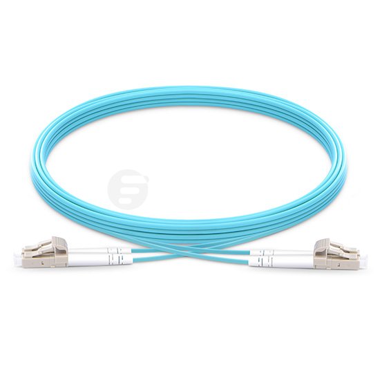
An early example of laser-optimized fiber is the Systimax Lazer SPEED fiber introduced by Lucent, which uses a green jacket to distinguish it from existing multimode (orange) , single-mode (yellow) , and dispersion-managed (purple) fiber cables. Attenuation is about 3.5 dB/km at 850 nm and 1.5 dB/km at 1300 nm; bandwidth is 2200 MHz*km at 850 nm (500 MHz*km overfilled) and 500 MHz*km at 1300 nm (no change when overfilled) . Another example is the Corning Infini-Core fiber, which typically uses an aqua-colored cable; the CL 1000 line consists of 62.5-micron fiber made with an outside vapor deposition process that achieves 500-m distances at 850 nm and 1 km at 1300 nm. Similarly, the CL 2000 line of 50-micron fiber supports 600-m distances at 850 nm and 2 km at 1300 nm. Here is a figure of OM3 multimode fiber for you.
Most recent installations of Ethernet, Fibre Channel, InifiniBand, and other systems use the preferred OM3 multimode fiber (for example, the OM3 SC to LC), and many legacy systems including ESCON are compatible with this fiber. In order to avoid the associated with installing new fiber, most standards attempt to accommodate various types of MMF. While the idea of backward compatibility works reasonably well up to 1 Gbit/s (distances of a few hundred meters can be achieved) , it begins to break down at higher data rates when the achievable distance is reduced even further. Designing a future-proof cable infrastructure under these conditions becomes increasingly difficult; at some point, new fiber needs to replace the legacy MMF. Although SMF should be a good long-term investment, the short-term cost premium for SMF installation and ports on many switches, servers, and storage devices remains a concern. Since the cost of short-wave transceivers is presently lower than long-wave transceivers, there is still some question as to the preferred fiber to install and the best mixture of 62.5-micron and 50-micron MMF. In general, 50-micron fiber has been widely deployed in Europe and Japen, while North America has primarily used 62.5-micron MMF until recently. The IEEE has recommended using 62.5-micron MMF in building backbones for distances up to 100m, and 50-micron fiber for distances between 100 and 300 m.
Mixing OM2 and OM3 fibers in the same link results in an aggregate bandwidth proportional to the weighted average of the two cable types. Care must be taken not to mix 50-and 62.5-micron fibers in the same cable plant, as the resulting mismatch in core size and numerical aperture creates high losses. This can make it difficult to administer a mixed cable plant, as there is no industry standard connector keying to prevent misplugging different types of MMF into the wrong location.
About the Author:
I am working in Fiberstore to share the fiber optic networking knowledge and products’ information with people. Fiberstore is a largest supplier of optical network solutions worldwide. You can get the cheapest fiber optic patch cords here.