Keyed LC System Secures Your Network

While we are chasing for higher data rates in fiber optic networks, data security is also an important concern for constructing good network environment. Data risks will increase in the expanded fiber optic networks when unauthorized or inadvertent data changes occur. In order to respond to the urgent demand, physically discrete fiber connection systems have emerged for security in high-performance fiber networks. Generally, we call it the keyed LC system. Data risks can be largely reduced at the early stage of the infrastructure design by using a new cabling solution of “keyed” characteristic. This article will take you to explore the world of keyed LC system.

What Is Keyed LC?

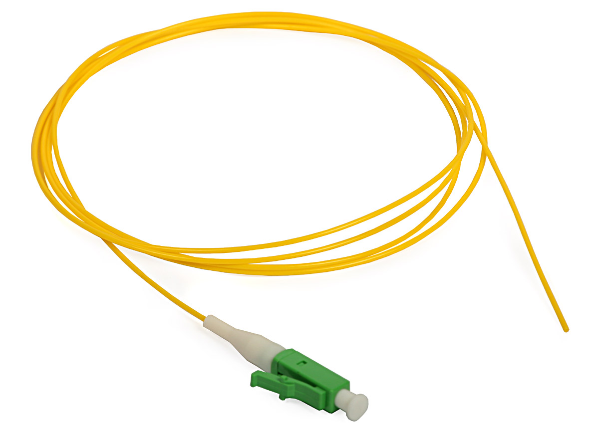
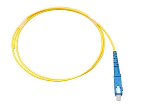
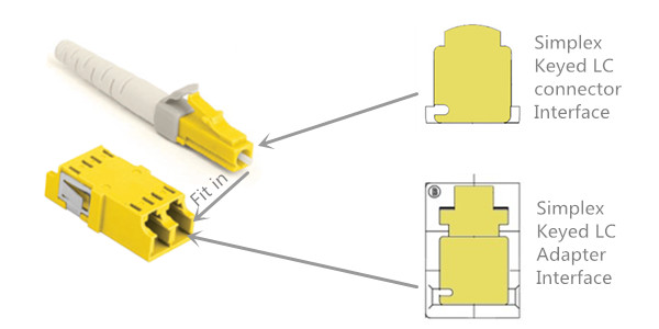
Keyed LC system or secure LC system is a small form factor (SFF) connection system that allows for physical segregation of network segments in secure fiber cabling infrastructure. Different colors are used in the system to identify different network circuits and protect them from accidental moves, adds, or changes. There are 8 or even 12 keying options for keyed LC components, thus 8 or 12 different colors are employed to correspond to the specific option. For instance, this picture shows the typical simplex keyed LC connectivity which only allows yellow colored interfaces to fit in with each other.

keyed-lc-connector-and-adapter

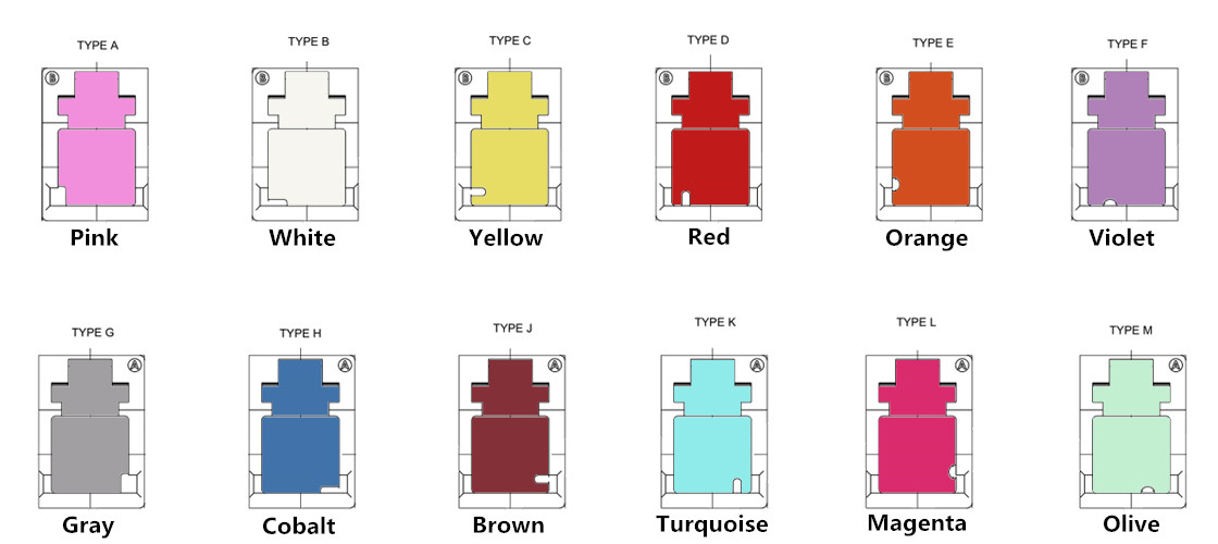
The following picture presents the 12 color coded patterns. Once the color does not match, the keying feature will prevent the connector from carrying the signal.

color-code-of-keyed-lc-products

Keyed LC System Components

Keyed LC system is a big family that contains various components. Most common members are keyed LC fiber optic connectors, keyed LC fiber patch cords, keyed LC fiber optic adapters, keyed LC fiber adapter panels and keyed LC fiber optic cassettes.

Keyed LC Fiber Optic Connectors & Patch Cords

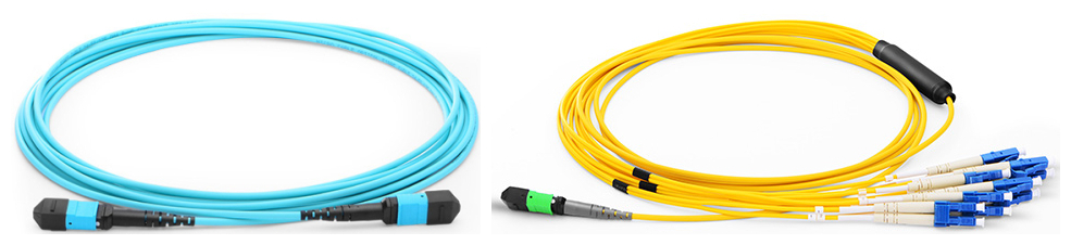
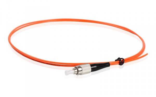
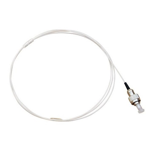
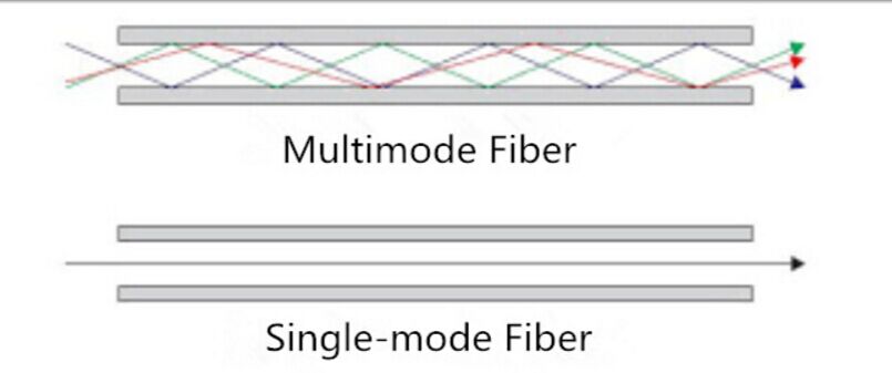
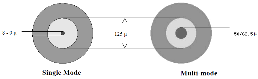
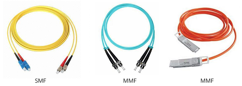
Keyed LC connectors are varied in different colors. When connectors are linked to fiber cables, they combine to be the diverse keyed LC patch cables. These components are used in interconnecting or cross-connecting fiber networks within a structured cabling system. Keyed LC fiber patch cables in single-mode 9/125 um, multimode 62.5/125 um, 50/125 um and laser-optimized 50/125 um are frequently used in the network.

Keyed LC Fiber Optic Adapters

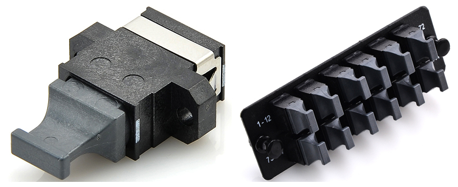
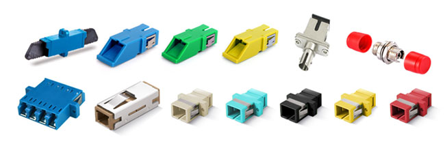
The front and back of keyed LC fiber optic adapters are both keyed to prevent installation errors and possible security breach. They have different color coded keyed patterns for identification and are available for both single-mode and multimode applications.

Keyed LC Fiber Adapter Panels

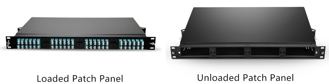
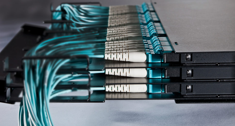
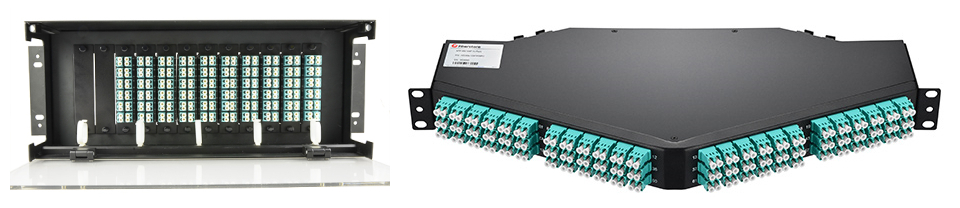
Keyed LC fiber adapter panels with 12, 16 and 24 fibers are available in the market. They are a widely recognized modular solution for restricted fiber cross-connect systems. In data center, equipment room and telecommunications room, keyed LC fiber adapter panels are now frequently used to improve data security levels.

Keyed LC Fiber Optic Cassettes

Keyed LC cassettes are widely applied to prevent unauthorized and inadvertent changes in the highly sensitive data center and IT network.

Benefits of Keyed LC Products
  • Point one — data security. It is the fundamental advantage of using keyed LC products. Data transmission is secured by multiple keying patterns. Networks can effectively be limited to certain groups, access levels or customers in a co-location environment, which provides an increased level of security and stability by protecting against incorrect patching of circuits.
  • Point two — easy identification. Color-coded keyed LC products are easy to be identified during cable installation and maintenance which saves lots of time.
  • Point three — higher performance.Keyed LC products are usually pre-terminated, which cause low insertion loss and greatly increase the fiber optic network performance.
  • Point four — flexibility. Two keyed simplex LC connectors can be easily assembled into a duplex LC connector. The polarity of a patch cord can also be reversed easily.
Summary

In conclusion, secure/keyed LC system is a modular connectivity system designed to secure fiber networks for higher performance. Great reliability can be achieved and installation becomes more efficient in all areas of a fiber cabling infrastructure.

UPC or APC – Which One to Choose?

When it comes to fiber optic cables, you might be curious about the description that contains UPC or APC. For example, what is LC UPC to LC UPC? And what is SC APC to SC APC? UPC and APC are actually two polish types of fiber ferrules. This article will help you explore the world of UPC and APC to know which one is the better solution for your network.

What is APC & UPC?

Return loss is inevitable when installing a connector on the end of fiber. It is a back reflection generated by the light source. However, severe light loss will damage the laser light sources and disrupt transmitted signals. Therefore, different polish connector ferrules are made to avoid serious return loss. UPC and APC are two widely used polish types. Here are some specific information about UPC and APC.

UPC, namely ultra physical contact, is evolved from PC with a better surface finish. UPC connector relies on machine polishing to deliver its low optical return loss characteristics. Its rounded finish created during the polishing process allows fibers to touch on a high point near the fiber core where light travels. In addition, when using the UPC connector, make sure your laser’s specifications can handle the return loss your UPC connector will generate.

UPC

APC, namely angled physical contact, is very different from UPC. The end face of APC connector is precisely polished at an 8-degree angle to the fiber cladding so that most return loss is reflected into the cladding where it cannot interfere with the transmitted signal or damage the laser source. But it is extremely difficult to field terminate an APC connector at 8 degrees with any consistent level of success. Therefore, if an APC connector is damaged in the field, it should be replaced with a factory terminated APC connector.

APC

How to Distinguish UPC from APC?

Many differences can be found between UPC and APC connectors:

Point one, end faces. As we have discussed before, UPC connectors are polished with no angle, but APC connectors is polished at an 8-degree angle.

Point two, ways of light reflection. Their different polish end faces directly lead to their differences in ways of light reflection. Any reflected light is reflected straight back towards the light source if an UPC connector is used. But the APC connector causes reflected light to reflect at an angle into the cladding instead of straight back toward the source.

Point three, return loss. Since their light reflection patterns are varied, their levels of return loss are also different. APC connector offers lower return loss of -65 dB than UPC of -50 dB. As a matter of fact, connectors can achieve better matching performance if return loss is lower.

Point four, connector color. This is the most obvious difference that can be seen from the surface. UPC connector usually has a blue body while APC connector has a green body.

Which One to Choose?

If you are still confused about which polish type to choose, the best way is to see whether their applications complies to yours. In general, the APC type has a better performance than the UPC type. APC is best for high bandwidth applications and long haul links. For example, FTTx (fiber to the x), passive optical network (PON) and wavelength-division multiplexing (WDM) that are more sensitive to return loss, thus APC is a better solution to offer the lowest return loss. However, massive employment of APC connectors will cause higher cost. In this way, UPC might be a better choice because cost budget is of equal importance.

Conclusion

UPC and APC are taken into consideration when choosing fiber optic patch cables. Both of them can reduce light loss and protect laser sources from damage. A wise selection should be based on your actual condition. Hope this article can provide you some help.

Have You Chosen the Right Fiber Patch Panel?

Fiber patch panel, namely fiber enclosure, is employed for better cable management and cable protection in data centers. With the help of fiber patch panels, it is more time-saving and easier for technicians to do the cabling work. Fiber patch panel terminates the fiber optic cables and provides access to the cables’ individual fibers for cross connection. In today’s market, there are various types of fiber patch panels. Choosing the right one for your network may seem a little complicated. This article will give several aspects that are important for selecting fiber patch panels.

Some Aspects for Consideration
Loaded vs. Unloaded

Loaded patch panel is pre-installed with adapter panels or cassettes while unloaded patch panel is empty with nothing inside. Typically, LC and MTP connectors are widely used in loaded patch panels. But these connectors in loaded panels are often permanently mounted, so if a port gets damaged it’s dead forever. Unloaded patch panel, on the contrary, is more flexible that can let you swap out defective ports at will. But extra assemblies are demanded to be purchased and installed by yourself.

loaded-unloaded-patch-panel

Patch Panel Rack Size

Fiber patch panel is usually measured by rack unit. A rack unit is used to describe the height of electronic equipment designed to mount in a 19-inch wide rack or a 23-inch wide rack. The height of rack-mounted equipment is frequently described as a number with U or RU. 1U refers to one rack unit, 2U refers to two rack units and so on. 2RU and 4RU are often used for high-density installations. So according to your application, the related rack size should also be adjusted.

patch-panel-rack-unit

Port Density

Port density is also an important part to be considered when purchasing fiber patch panels. As for normal patch panel, 1RU is able to carry 48 ports. If high-density patch panel is required, 1RU can support 96 ports. Moreover, 144 ports in 1RU is also available with ultra density patch panels. Since high-density has been frequently applied to the data centers, patch panels with higher port density becomes the future trend.

Migration to High-Density Patch Panels

Nowadays, people are paying more attention to the 40G and 100G high speed networks. MPO/MTP breakout patch panel may be an ideal solution for this high-density installation. Deploying high-density patch panels has many advantages. It simplifies the cabling deployment by running a short fiber patch cable from your SAN or network switch up to the fiber patch panel. Much space can also be saved in data centers by mounting more cables into a smaller space. Installation is easier since no tools are required to install cassettes in the patch panels, and push-pull tabs are used to ease the difficulty of cable connections in the patch panels. After all, high-density patch panel is a cost-effective solution that overcomes the cabling congestion in high bandwidth networking.

high-density-fiber-patch-panel

Summary

The well-organized and well-protected cables are the guarantee of a stable network. Fiber patch panel is definitely the perfect solution that meets all the requirements. Choosing the right fiber patch panel is also beneficial to your network. You may consider from the aspects of loaded or unloaded types, rack size, port density, etc. In addition, high-density fiber patch panel is welcome by the 40G/100G network. If you want to achieve better high bandwidth application, patch panels with high-density ports are recommended.

Optical Transport Network (OTN) for High Speed Service

Nowadays, the SONET/SDH network is an universal network that combines with WDM (wavelength division multiplexing) technique to transmit multiple optical signals over a single fiber. In future networking, high speed transmission is no doubt the migration trend. Inspired by the SONET/SDH network, ITU-T (ITU Telecommunication Standardization Sector) has defined the optical transport network (OTN) to achieve a more cost-effective high speed network with the help of WDM technology.

Generally speaking, OTN is a network interface protocol put forward in ITU G.709. OTN adds OAM (operations, administration and maintenance) functionality to optical carriers. It allows network operators to converge networks through seamless transport of the numerous types of legacy protocols, while providing the flexibility required to support future client protocols. Unlike the previous SONET/SDH, OTN is a fully transparent network that provides support for optical networking on a WDM basis. Since multiple data frames have been wrapped together into a single entity in OTN, it is also known as the “digital wrapper”.

Working Principle of OTN

You may wonder how OTN works in practice. Actually, its working structure and format very resemble the SONET/SDH network. Six layers are included in the OTN network: OPU (optical payload unit), ODU (optical data unit), OTU (optical transport unit), OCh (optical channel), OMS (optical multiplex section) and OTS (optical transport section).

OPU, ODU and OTU are the three overhead areas of OTN frame. OPU is similar to the “path” layer of SONET/SDH, which provides information on the type of signal mapped into the payload and the mapping structure. ODU resembles the “line overhead” layer of SONET/SDH, which adds the optical path-level monitoring, alarm indication signals, automatic protection switching bytes and embedded data communications channels. OTU is like the “section overhead” in SONET/SDH, and it represents a physical optical port that adds performance monitoring and FEC (forward error correction). OCh is for the conversion of electrical signal to optical signal and modulates the DWDM wavelength carrier. OMS multiplexes several wavelengths in the section between OADMs (optical add drop multiplexer). OTS manages the fixed DWDM wavelengths between each of the in-line optical amplifier units.

OTN-structure

Advantages of OTN

There are many advantages of OTN. Firstly, it separates the network against uncertain service by providing transparent native transport of signals encapsulating all client-management information. Secondly, it performs multiplexing for optimum capacity utilization which enhances network efficiency. Thirdly, it improves maintenance capability for signals transmitting through multi-operator networks by providing multi-layer performance monitoring.

Migration to High Speed OTN

With the fast evolution of networking, OTN standard is able to reach a higher speed service. Its multiplexing hierarchy allows any OTN switch and any WDM platform to electronically groom and switch lower-rate services within 10 Gbps, 40 Gbps, or even 100 Gbps wavelengths. This eliminates the need for external wavelength demultiplexing and manual interconnects. OTN network is definitely the best solution for future high speed networking over long distance. The picture below shows the OTN mapping diagram for high speed transmission.

OTN-high-speed-mapping-diagram

Conclusion

Over the years, OTN has never stopped improving itself. Driven by the needs for high speed transmission, OTN combined with WDM is obviously a better choice in networking. It is a cost-effective way to build an optical transport network accommodating high throughput broadband services. I believe more and more people will employ this standard in their own network in the near future.

MTP/MPO – An Easier Solution for High Density Patching

With the continuing growth of data throughput in networking, 40G network now becomes the commonplace and 100G has also been used increasing widespread. To achieve a higher transmission data rate, it is important to find a suitable solution for the high density cable routing. Thus, the arrival of MTP/MPO connection standard is a piece of good news for high density patching. The MTP/MPO technology is available with multi-fiber connectors which is a perfect solution for high-performance data transmission. There are a lot of benefits when adopting the MTP/MPO structure. This article will provide some effective MTP/MPO assemblies that are frequently used to meet high density demands.

Superiority of MPO/MTP Assemblies

Actual practice proves that MPO/MTP components are superior to other assemblies in high density applications. They can connect to equipment with various date rates of 10 Gbps, 40 Gbps or 100 Gbps, which makes them more flexible for the devices. Also, their installation is very simple. No tools are required to install the cassette in the panel enclosure, and the push-pull connection offers an easier way to be locked or unlocked in patch panels. Owing to the modular cassette system, they are also pretty adjustable in network reconfiguration. You may think this must cost you a great deal, however, the initial investment is very cost-effective.

Recommended MPO/MTP Products

Here are some recommended MPO/MTP products for high density patching. Using these assemblies can achieve a significant progress in operations.

1) MTP/MPO Cables

MTP/MPO cables consist of MTP/MPO connectors and fiber cables. Sometimes, other types of connector can also be linked to one termination. The fiber cables are usually employing OM3 or OM4 laser optimized multimode optical fibers. MTP/MPO trunk cables, harness/breakout cables and direct pigtails are three categories of MTP/MPO cables. The MTP/MPO trunk cables are available with 8, 12, 24, 36, 48, 72 and 144 fibers for single-mode and multimode applications. The harness/breakout cables is designed to work from trunk backbone assemblies to fiber rack system in the high density cabling. One end is terminated with a MTP/MPO connector, and the other end can have other options of connectors such as LC/SC/ST/MTRJ. The MTP/MPO pigtail cables are typically used for splicing directly inside fiber management panels near adapter ends.

mtp-mpo-cable

Appropriate utilization of MTP/MPO cassettes can help reduce installation time and investment for an optical network infrastructure in the premises. Rapid deployment of high density data center infrastructure can also be realized thanks to the modular system. The MTP/MPO plug-n-play cassette provides the interconnection between MTP/MPO backbones with LC/SC/ST/FC patching. Other recommended cassettes are 1U 19” rack mount cassettes holders, 4U 19” rack mount cassettes holders and 144 ports ultra HD angled patch panel. 1U 19” rack mount enclosure is integrated with three pieces of plug-n-play cassettes for up to 72 fibers patching. 4U 19” rack mount enclosure has 12 plug-n-play cassette pieces with 288 fibers patching. 144 ports ultra high density cassette is equipped with 72 LC duplex adapters for 144 fibers patching.

mtp-mpo-cassettes

3) MTP/MPO Optical Adapter & Adapter Panels

The black colored MTP/MPO adapter has two types as key-up to key-down and key-up to key-up. It provides the connection between cable to cable or cable to equipment in the MTP/MPO style. The MTP/MPO fiber adapter panels are available with 2, 3, 4, 6, 8, 12, 16 and 18 ports both horizontally and vertically in lighter package.

mtp-mpo-optcial-adapter-and-adapter-panels

Conclusion

In summary, if you need devices for high density deployment, MTP/MPO assemblies are absolutely best solutions. Applying the MTP/MPO connection, its patch cables, cassettes and adapters will be promoted to a more effective use.

OADM – Optical Add-Drop Multiplexer

With the development of optical communication technologies, people are entering into the new era of information. In order to overcome the data rate limitation of traditional communication system, WDM and OTDM technologies are typically used to increase fiber optic bandwidth. However, no matter which kind of technology is adopted to construct fiber optic network, optical add-drop multiplexer (OADM) technology is needed in the system. It makes the fiber optic network more flexible, optional and transparent. OADM is now a key component of the all-optical network to enhance the network reliability and efficiency. This article will give a brief introduction about the basic knowledge of OADM.

OADM

Definition of OADM

So what is an optical add-drop multiplexer or OADM? To be specific, an OADM is a device used in wavelength-division multiplexing systems for multiplexing and routing different channels of light into or out of a single-mode fiber. “Add” refers to the capability of the device to add one or more new wavelength channels to an existing multi-wavelength WDM signal. On the contrary, “drop” refers to its ability of removing one or more channels and passing those signals to another network path.

There are three parts of a traditional OADM – an optical demultiplexer, an optical multiplexer and a reconfiguration method between the demultiplexer and the multiplexer. The demultiplexer separates wavelengths from an input fiber onto different ports. The multiplexer multiplexes the wavelength channels that come from demultiplexer ports with those from the add ports onto a single output fiber. The reconfiguration can be achieved by a fiber patch panel or by optical switches which direct the wavelengths to the multiplexer or to drop ports.

Operating Principle of OADM

The WDM signal contains multiple wavelength channels. When these wavelengths enter into the main input of OADM, they can be selected to enter the drop output ports according to your application requirements. Correspondingly, the add ports will input the required wavelength channels. And those irrelevant wavelengths will directly pass through OADM and then be multiplexed with the added wavelengths together leaving the main output. Therefore, the function of OADM is to download necessary local signals and upload signals for the user of next node.

OADM-operating-principle

Two Kinds of OADM

Fixed OADM and reconfigurable OADM are two commonly used types of OADM. The former is used to drop or add data signals on dedicated WDM channels, and the latter is used to electronically alter the selected channel routing through the optical network.

Fixed OADM or FOADM is the traditional construction of OADM. It uses a filter to select a dropping wavelength and a multiplexer to add a new channel at the same wavelength. Different from FOADM, reconfigurable OADM or ROADM is a dynamic type which has the ability to remotely switch traffic from a WDM system at the wavelength layer. It provides flexibility in rerouting optical streams, avoids faculty connections, and allows minimal service disruption and the ability to adapt or upgrade the optical network to different WDM technologies.

Conclusion

OADM is an important element of an optical fiber network. It can be both deployed for long-haul core networks or short metro networks. Fixed OADM and reconfiguration OADM are two commonly used types. A further development of OADM is absolutely the future trend in fiber optic communications.

Introduction to Simplex, Half Duplex and Full Duplex

Simplex, half duplex and full duplex are three kinds of communication channels in telecommunications and computer networking. These communication channels provide pathways to convey information. A communication channel can be either a physical transmission medium or a logical connection over a multiplexed medium. The physical transmission medium refers to the material substance that can propagate energy waves, such as wires in data communication. And the logical connection usually refers to the circuit switched connection or packet-mode virtual circuit connection, such as a radio channel. Thanks to the help of communication channels, information can be transmitted without obstruction. A brief introduction about three communication channel types will be given in this article.

Three Types of Communication Channel
1) Simplex

A simplex communication channel only sends information in one direction. For example, a radio station usually sends signals to the audience but never receives signals from them, thus a radio station is a simplex channel. It is also common to use simplex channel in fiber optic communication. One strand is used for transmitting signals and the other is for receiving signals. But this might not be obvious because the pair of fiber strands are often combined to one cable. The good part of simplex mode is that its entire bandwidth can be used during the transmission.

Simplex

2) Half duplex

In half duplex mode, data can be transmitted in both directions on a signal carrier except not at the same time. At a certain point, it is actually a simplex channel whose transmission direction can be switched. Walkie-talkie is a typical half duplex device. It has a “push-to-talk” button which can be used to turn on the transmitter but turn off the receiver. Therefore, once you push the button, you cannot hear the person you are talking to but your partner can hear you. An advantage of half-duplex is that the single track is cheaper than the double tracks.

Half-Duplex

3) Full duplex

A full duplex communication channel is able to transmit data in both directions on a signal carrier at the same time. It is constructed as a pair of simplex links that allows bidirectional simultaneous transmission. Take telephone as an example, people at both ends of a call can speak and be heard by each other at the same time because there are two communication paths between them. Thus, using the full duplex mode can greatly increase the efficiency of communication.

Full-Duplex

A simplex fiber optic cable has only one tight-buffered fiber inside cable jacket for one-way data transmission. The aramid yarn and protective jacket enable the cable to be connected and crimped to a mechanical connector. It can be used for both single-mode and multimode fiber optic cables. For instance, single-mode simplex fiber optic cable is suitable for networks that require data to be transmitted in one direction over long distance.

Different from simplex fiber optic cable, the duplex one has two fibers constructed in a zipcord style. It is often used for duplex communication between devices to transmit and receive signals simultaneously. The duplex fiber optic cable is required for all sorts of applications, such as workstations, fiber switches and servers, fiber modems and so on. And single-mode or multimode cable is also available with duplex cables.

Conclusion

The concept of communication channel is important for understanding the operation of networking. Simplex, half duplex and full duplex are three modes of communication channels. Each of them can be deployed for different applications. It is more cost-effective to choose the right fiber optic cable according to its channel mode.

Related Article: Simplex vs Duplex Fiber Optic Cables
SFP LC SX Vs. LX Transceiver

Getting to Know PoE Network

With the rapid development of networking, a variety of technologies have been created. In 2003, PoE (power over Ethernet) network technology has been standardized. And it is now widely used for wireless LANs (local area networks), IP cameras and VoIP (voice over Internet protocol) phones. PoE allows cables to carry both electrical power and data signal to devices. Electrical current will support the operation of devices which greatly reduces the amount of wires used for network installation. Thus, the emergence of PoE network is absolutely a good news for the development of cost-efficient networking. Next, more information about PoE network will be discussed in the following paragraphs.

PoE-network

Operating Principle of PoE

There are three basic components in PoE system – PSE, PD and Ethernet cable. PSE (power sourcing equipment) like PoE switch is the device used for delivering power to cable. PD (powered device) is the device used for receiving power from the cable. And cable will help transmit the electrical power and data signal. The electrical current will first go into the cable at the PSE end, and then come out at the PD end. Since it is the transmission of electric signal, PoE is only available to twisted pair Ethernet cabling. Also, the current is separated from data signal so that neither of them interferes with the other.

Advantages of PoE

Using the PoE network has many advantages:

  • Flexibility
    Because devices like IP cameras and wireless access points are not permanently attached to an electrical outlet, they can be located regardless of area restriction. Reinstallation is also easy to implement.
  • Safety
    PoE network is designed to be safe enough to protect network equipment from overload, underpowering, or incorrect installation.
  • Dependability
    PoE power comes from a central and universally compatible source instead of a collection of distributed wall adapters. And an uninterruptible power supply is backing up the PoE network for a more stable operation.
  • Scalability
    Owing to the electrical power available on PoE network, the installation and distribution of network connections are more simple and effective.
Applications of PoE

VoIP phones, WLAN, RFID (radio frequency identification), security cameras or access control devices are major applications for PoE network. Using PoE network enables the VoIP to receive uninterrupted power through the network, without the need for an AC outlet for each phone. And WLAN access point can be placed in different locations such as ceilings, hallways, lobbies without electrical outlets. Likewise, PoE allows RFID readers to be strategically situated in locations that optimize effectiveness. And it is cheaper to use PoE network for security cameras or access control devices on ceilings, hallways, lobbies, or outdoor areas.

Conclusions

To sum up, the advent of PoE has greatly improved the effectiveness of network. Equipment are able to be located at any place due to the power availability. And a large number of cost will be saved by eliminating unnecessary wires. This article only gives a brief introduction to the PoE network. There still has a lot for us to explore.

Related Article: Introduction to PoE Networking Architectures

Categories of Twisted Pair Introduction

As one of the oldest types of cable ever invented, twisted pair cabling was first developed by Alexander Graham Bell in 1881. Since then, it has been widely deployed for telephone line network in America. Nowadays, their are various categories of twisted pair cables have been extended worldwide mainly for outdoor land lines offering telephone voice service.

Generally speaking, twisted pair cabling is a kind of copper wiring that two conductors of a single circuit are twisted together. The purpose of using twisted pair is to offset electromagnetic interference (EMI) from external sources to stop degrading the performance of circuit. Also, different standards of twisted pair are specified into various categories as cat 1, cat 2, cat 3, cat 4, cat 5/5e, cat 6/6a, cat 7/7a, cat 8/8.1/8.2. And this article will give a brief introduction to some common categories of twisted pair cables.

categories of twisted pair cables

Different Categories of Twisted Pair
1) Cat 5/5e

Cat 5 twisted pair cable is often used for structured cabling of computer networks. It is available to 10/100 Mbps speeds at up to 100 MHz bandwidth. However, it is now considered to be obsolete and replaced by cat 5e (enhanced). Cat5e cable is one the most commonly used twisted pair cables at present. The biggest distinction between cat 5 and cat 5e is that cat 5e has a lower cross talk and its transmitting speed can reach up to 1000 Mbps.

2) Cat 6/6a

As a substitute of cat 5/5e, cat 6 twisted pair is applied to Gigabit Ethernet and other network physical layers. It supports up to 10 Gbps speed at 250 MHz. When used for 10GBASE-T applications, Cat6 cable has a reduced maximum length from 37 to 55 meters. But cat 6a (augmented) has been evolved to perform at up to 500 MHz, thus the maximum cable distance is longer than cat 6 of up to 100 meters.

3) Cat 7/7a

Cat 7 is the standard for twisted pair cabling used for 1000BASE-T and 10GBASE-T networks. It provides performance of up to 600 MHz with a maximum length of 100 meters. As for the cat 7a (augmented) cable, it has a higher frequency of 1000 MHz. Results show that it may be possible to support 40 GbE or even 100 GbE at a very short length.

4) Cat 8/8.1/8.2

Cat 8 is the USA standard specified by ANSI/TIA while cat 8.1 and cat 8.2 are specified by ISO/IEC for global application. All these three kinds of cat 8 twisted pairs are used for 25GBASE-T and 40GBSE-T at the maximum frequency of up to 2 GHz. Except cat 8 adopts cat 8 links, cat 8.1 uses class I links and cat 8.2 uses class II links. The key difference between class I and class II is that class II allows three different styles of connectors to be not compatible with one another, or with the RJ45 connector.

Conclusion

Twisted pair cables have been classified into different grades called categories. These standards especially formulate the data capacity of the cable. Higher categories are more expensive than lower ones, but most of cost is actually spent on labor force for installing the cables. And twisted pair cables under cat 5 are not recommended now. Higher categories are the future trends for network cabling.

Introduction to Fiber Optic Pigtails

During the process of fiber optic cable installation, cable connection is important to ensure the low attenuation and low return loss of signal transmission between cable and equipment. And fiber optic pigtail is a commonly used component for the connection of optical network. It is a piece of cable terminated with fiber optic connectors at one end and no connector at the other end. In this way, the connector side can be linked to the equipment and the other side can be fused with optical cable fibers. This article will emphasize on the types of fiber optic pigtails and their applications.

Here are two classifications of fiber optic pigtails. Firstly classified by connectors, fiber optic pigtails has seven types including E2000, LC, SC, ST, FC, MU and MTRJ. Secondly classified by fibers, fiber optic pigtails has two types as single-mode and multimode.

Classification of Connector

LC-fiber-optic-pigtail

1)LC fiber optic pigtail uses the LC connector developed by Lucent Company. LC connector is now one of the most popular connectors in the world. A 1.25mm ceramic ferrule makes LC fiber optic pigtail a better choice for low cost but high precision signal transmission.

SC-fiber-optic-pigtail

2) SC fiber optic pigtail uses the SC connector developed by Nippon Telegraph and Telephone. SC connector has a ceramic ferrule of 2.5 mm. Its light weight and cost-effective features enable different applications of SC fiber optic pigtail.

ST-fiber-optic-pigtail

3)ST fiber optic pigtail uses the ST connector developed by American Telephone & Telegraph. ST connector has a 2.5mm bayonet-styled ferrule. It is one of the eldest generations of fiber optic connectors. But it is still used for many fiber optic applications, especially for multimode fiber optic communications.

FC-fiber-optic-pigtail

4)FC fiber optic pigtail uses the FC connector developed by Nippon Electric Company. The connector features the screw type structure and high precision ceramic ferrule. FC fiber optic pigtail is usually used for general fiber optic applications.

Classification of Fiber Types

Single-mode fiber and multimode fiber are both used for fiber optic pigtails. The single-mode fiber optic pigtail has a 9/125 micron core size. SC, LC, ST, FC and E2000 connectors are all fit for this kind of fiber. As for multimode fiber optic pigtails, there are two different core sizes. One is 62.5/125 micron of OM1, and the other is 50/125 micron of OM2, OM3, OM4. SC, LC, ST, FC connectors are adaptable to multimode fiber optic pigtails.

Applications

Fiber optic pigtail sometimes has multiple fiber strands, including 4 fibers, 6 fibers, 8 fibers, 12 fibers, 24 fibers, 48 fibers and so on. This helps the effective interconnection and cross-connect in various applications. Since fiber optic pigtail supports fusion splicing, it is often used with devices like optical distribution frames, splice closures and cross cabinets.

Conclusion

In summary, fiber optic pigtail is a cable that only one end is terminated with connectors. The other end can be melted with optical fiber for a permanent connection. You may choose the adaptable fiber optic pigtail from the perspective of connector types, fiber types, strand numbers, etc. Hope this article can provide a little help.

Comparison Between CWDM & DWDM Technology

For a better signal transmission in fiber-optic communication, different kinds of technologies are applied to the industry. Wavelength-division multiplexing (WDM) is one of the commonly used technologies which multiplexes a number of optical carrier signals onto a single optic fiber by using different wavelengths of laser light. That is to say, WDM enables two or more than two wavelength signals to transmit through different optical channels in the same optical fiber at the same time.

WDM

In the WDM system, there are two types of divisions – CWDM (coarse wavelength division multiplexing) and DWDM (dense wavelength division multiplexing). They are both using multiple wavelengths of laser light for signal transmission on a single fiber. However, from the aspects of channel spacing, transmission reach, modulation laser and cost, CWDM and DWDM still have a lot of differences. This article will focus on these distinctions and hope you can have a general understanding about CWDM and DWDM technology.

Channel Spacing

As their names suggest, the words “coarse” and “dense” reveal the difference in channel spacing. CWDM has a wider spacing than DWDM. It is able to transport up to 16 wavelengths with a channel spacing of 20 nm in the spectrum grid from 1270 nm to 1610 nm. But DWDM can carry 40, 80 or up to 160 wavelengths with a narrower spacing of 0.8 nm, 0.4 nm or 0.2 nm from the wavelengths of 1525 nm to 1565 nm (C band) or 1570 nm to 1610 nm (L band). It is no doubt that DWDM has a higher performance for transmitting a greater number of multiple wavelengths on a single fiber.

CWDM-VS-DWDM

Transmission Reach

Since the wavelengths are highly integrated in the fiber during light transmission, DWDM is able to reach a longer distance than CWDM. The amplified wavelengths provide DWDM with the ability of suffering less interference over long-haul cables. Unlike DWDM system, CWDM is unable to travel unlimited distance. The maximum reach of CWDM is about 160 kilometers but an amplified DWDM system can go much further as the signal strength is boosted periodically throughout the run.

Modulation Laser

CWDM system uses the uncooled laser while DWDM system uses the cooling laser. Laser cooling refers to a number of techniques in which atomic and molecular samples are cooled down to near absolute zero through the interaction with one or more laser fields. Cooling laser adopts temperature tuning which ensures better performance, higher safety and longer life span of DWDM system. But it also consumes more power than the electronic tuning uncooled laser used by CWDM system.

Cost

Because the range of temperature distribution is nonuniform in a very wide wavelength, so the temperature tuning is very difficult to realize, thus using the cooling laser technique increases the cost of DWDM system. Typically, DWDM equipment is four or five times more expensive than CWDM equipment.

Conclusion

CWDM and DWDM are both coming from the WDM technology that is capable of conveying multiple wavelengths in a single fiber. But with different characteristics, people should think twice before choosing the CWDM or DWDM system. CWDM usually costs less but its performance is far behind DWDM. Both your requirements and budget need to be taken into consideration. Moreover, the WDM products including CWDM mux/demux module, DWDM mux/demux module and optical splitter are highly welcome in the market.

Guide to Fusion Splicer Selection

Optic fiber is now widely applied to networks around the globe. When it comes to actual operation, connecting fibers is a necessary task. And fusion splicer is an effective tool for fiber optic splicing. But choosing the right type of fusion splicer is still a challenge. In this article, we will talk about how to find the most matching fusion splicer.

Before discussing about different types of fusion splicer, let’s first have a look at the working principle and specific function of a fusion splicer. The fusion splicer is the device that uses heat to melt the ends of two optic fibers and combines them together into one fiber. By using the fusion splicer, the joint is permanent so that light signals can pass from one fiber to another with little link loss. The heating source of a fusion splicer can be a laser, a gas flame, a tungsten filament or a electric arc. And the most popular heating source at present is electric arc.

Nowadays, there are two types of fusion splicer according to different aligning systems. One is called the core alignment fusion splicer, the other is cladding alignment fusion splicer. If you can figure out the differences between these two types of fusion splicer, finding a right fusion splicer is no longer a problem.

Core Alignment Fusion Splicer

Core alignment is the most welcome fusion splicing technology at present. The splicer combines the image and light detection systems which can view the fibers cores in order to measure and monitor core position. Fiber cores are put in V-grooves and are aligned horizontally (X-axis), vertically (Y-axis) and in/out (Z-axis). The type of fusion splicer is adaptable for all kinds of fibers, such as single-mode or multimode fiber, good or bad fiber and splicing old fiber to new fiber. It is much more expensive but provides a more precised alignment.

Core-Alignment-Fusion-Splicer

Cladding Alignment Fusion Splicer

Cladding alignment is also called as passive alignment or fixed V-groove type. This type of fusion splicer relies on the accurate pre-alignment of fiber V-grooves that grip the outer surface or cladding of the fiber. Fiber cores are adjusted inwards and outwards. This type of fusion splicer is only available for multimode fiber or good single-mode fibers. As to cladding alignment fusion splicer, the cost is lower and alignment is faster, but its demand for the quality of fiber is higher or else will cause a lot of losses.

Cladding-Alignment-Fusion-Splicer

Suggestions For Fiber Optic Splicing

Though the two types of fiber optic splicing are different, the methods for better splicing are common. Here are some suggestions for fiber optic splicing:

1. Clean the fusion splicer before splicing. Any invisible contamination will cause tremendous problems when splicing the fibers.

2. In order to increase the alignment speed for fusion splicer, it is important to maintain and operate other tools, such fiber cleaver. A good cleaving will save time for splicing and decrease fiber loss.

3. Make sure the fusion parameters are adjusted minimally and methodically. The changes of parameters will also generate problems for your desired setting.

Conclusion

Selecting a suitable fusion splicer is beneficial to the splicing process. You may consider your needs and affordable cost to find the right fusion splicer. Core alignment fusion splicer has a better performance but a higher price than cladding alignment fusion splicer. Please choose your ideal fusion splicer wisely and do not forget to follow the normative operation for your splicing.

What is FTTx Network?

FTTx

Since the customers have demanded for a more intensive bandwidth, the telecommunication carriers must seek to offer a matured network convergence and enable the revolution of consumer media device interaction. Hence, the emergence of FTTx technology is significant for people all over the world. FTTx, also called as fiber to the x, is a collective term for any broadband network architecture using optical fiber to provide all or part of the local loop used for last mile telecommunications. With different network destinations, FTTx can be categorized into several terminologies, such as FTTH, FTTN, FTTC, FTTB, FTTP, etc. The following parts will introduce the above terms at length.

FTTH

FTTx is commonly associated with residential FTTH (fiber to the home) services, and FTTH is certainly one of the fastest growing applications worldwide. In an FTTH deployment, optical cabling terminates at the boundary of the living space so as to reach the individual home and business office where families and officers can both utilize the network in an easier way.

FTTN

In a FTTN (fiber to the node) deployment, the optical fiber terminates in a cabinet which may be as much as a few miles from the customer premises. And the final connection from street cabinet to customer premises usually uses copper. FTTN is often an interim step toward full FTTH and is typically used to deliver advanced triple-play telecommunications services.

FTTC

In a FTTC (fiber to the curb) deployment, optical cabling usually terminates within 300 yards of the customer premises. Fiber cables are installed or utilized along the roadside from the central office to home or office. Using the FTTC technique, the last connection between the curb and home or office can use the coaxial cable. It replaces the old telephone service and enables the different communication services through a single line.

FTTB

In a FTTB (fiber to the building) deployment, optical cabling terminates at the buildings. Unlike FTTH which runs the fiber inside the subscriber’s apartment unit, FTTB only reaches the apartment building’s electrical room. The signal is conveyed to the final distance using any non-optical means, including twisted pair, coaxial cable, wireless, or power line communication. FTTB applies the dedicated access, thus the client can conveniently enjoy the 24-hour high speed Internet by installing a network card on the computer.

FTTP

FTTP (fiber to the premise) is a North American term used to include both FTTH and FTTB deployments. Optical fiber is used for an optical distribution network from the central office all the way to the premises occupied by the subscriber. Since the optical fiber cable can provide a higher bandwidth than copper cable over the last kilometer, operators usually use FTTP to provide voice, video and data services.

FTTx Network Applications

With its high bandwidth potential, FTTx has been closely coupled with triple play of voice, video and data services. And the world has now evolved beyond triple play to a converged multi-play services environment with a high bandwidth requirement. Applications like IPTV, VOIP, RF video, interactive online gaming, security, Internet web hosting, traditional Internet and even smart grid or smart home are widely used in FTTx network.

Conclusion

FTTx technology plays an important part in providing higher bandwidth for global networks. According to different network architectures, FTTx is divided into FTTH, FTTN, FTTC, FTTB, FTTP, etc. FS.COM provides FTTx solutions and tutorials for your project, please visit FS.COM for more information.

Introduction to Fiber Optic Adapter

A small equipment used for connecting optical fiber cables together is often called as fiber optic adapter or fiber optic coupler. Although they may shape differently, they have the same function. A fiber optic adapter allows fiber optic cables to be attached to each other singly or in a large network, permitting many devices to communicate at once. According to different shapes and structures, fiber optic adapters can be classified in several types, such as FC fiber optic adapter, SC fiber optic adapter, ST fiber optic adapter, LC fiber optic adapter and so on. And this article will particularly introduce these four kinds of fiber optic adapters.

fiber-optic-adapters

FC Fiber Optic Adapter

FC fiber optic adapter uses a metal sleeve to strengthen its outer structure and can be fastened by a turnbuckle. It also adopts the ceramic pins as its butt end. Therefore, FC fiber optic adapter is able to sustain a stable optical and mechanical performance for a long time. It can be divided into square type, oval type and round type in single-mode and multimode versions. FC fiber optic adapter is easy to operate but sensitive to dust, so it has been enhanced today by using spherical butt end without changing its external structure.

SC Fiber Optic Adapter

Covered with a rectangular shell, SC fiber optic adapter has the same configuration and size of the coupling pin cover as FC fiber optic adapter. From its structures, SC fiber optic adapter can be classified into simplex standard, duplex standard and shuttered standard. From its materials, metal and plastic are commonly used for SC fiber optic adapter. SC fiber optic adapter enables a high precision alignment with a low insertion, return loss and back reflection.

ST Fiber Optic Adapter

ST fiber optic adapter has a key snap-lock structure to ensure accuracy when connecting the cables together. The repeatability and durability of ST fiber optic adapter is improved by the metal key. With a precised ceramic or copper cover, ST fiber optic adapter can also keep a high optical and mechanical performance for a long time. It has two standards of simplex and duplex and uses the metal or plastic housing.

LC Fiber Optic Adapter

LC fiber optic adapter adopts the modular jack latch mechanism which is easy to operate. Using the smaller pins and sleeves, LC fiber optic adapter greatly increases the density of fiber optic connector. There are three types of LC fiber optic adapter in simplex, duplex and quad structures.

Applicable End Faces

Different fiber optic adapters supports different ends faces. PC (physical contact), UPC (ultra physical contact) and APC (angle physical contact) are the polish style used for fiber optic adapters. ST fiber optic adapter is only available with PC and UPC styles. But except ST, the rest three fiber optic adapters support all the polish styles. Moreover, the color of fiber optic adapters can be used to define different end faces of PC, UPC and APC. For example, as for SC and LC fiber optic adapters, there are cream, blue and green colors which correspond to PC, UPC and APC end faces.

Application

In order to help the signal transmission, fiber optic adapter is widely used for telecommunications system, cable TV network, LAN (local area network), WAN (wide area network), FTTH (fiber to the home), video transmission and instrument testing. It is no doubt that fiber optic adapter is of great help for network communications.

Conclusion

Fiber optic adapter provides convenience for fiber cable connections. FC, SC, ST, LC fiber optic adapters are parts of the adapter family and are widely adopted in practical use. Small device like fiber optic adapter really helps a lot for different applications in life, because it greatly improves the working efficiency.

Comparison Between MMF and SMF Optical Cables

According to different standards, fiber optic cable can be categorized into different classifications. One way is to classify the cable into single mode fiber (SMF) and multimode fiber (MMF). The comparison between these two types of optical cables can assist you in choosing the most suitable cable for device. This article will compare the two kinds of cables from cable path, distance, precision termination, cost and color. Hope you can find some useful information from the article.

Single Path Vs. Multiple Paths

SMF uses laser light which usually follows a single path through the fiber. MMF takes multiple paths, which may result in a differential mode delay. Each type of fiber can be applied for different equipment. It’s important to know which application is more suitable for practical use. Otherwise, it will not operate at optimal levels.

SMF-and-MMF-paths

Short Distances Vs. Long Distances

SMF is used for long distance communication, and MMF is used for distances of 500m or less. Each type is equally as effective when chosen for the proper communication device. Make sure to check the ratings to determine which type is best for your application. The distances should be clearly marked.

Thick Core Size Vs. Thin Core Size

SMF typically has a smaller core size of 8.3 to 10 microns in diameter which is more precise for signal transmission in long distance, while the core size of MMF is much larger than SMF from 50 to100 microns in diameter which is more suitable for short distance transmission owing to the signal distortion. With a thinner core size, SMF is only allowed to carry a single light-wave along a single path, while the thick core size makes MMF able to carry different light-waves along numerous paths without modal dispersion limitation.

SMF-and-MMF-core-size

Low Cost Vs. High Cost

MMF is typically a lower cost solution than SMF. Limited budget may prompt designers to seek solutions with MMF fiber optic cables. The equipment that’s used for communications over MMF is usually less expensive than SMF. But the typical transmission speed and distance of MMF have limitations of 100 Mbit/s for distances up to 2 km.

Color Differences

MMF and SMF cables can also be distinguished by color. Usually, yellow is used for SMF cable color and orange or aqua is used for MMF cables. It is much easier to distinguish them just by their appearance color.

SMF-and-MMF

Other Primary Differences

MMF is typically characterized by having a larger core diameter. In most cases, it’s larger than the wavelength of light it supports. Therefore, MMF has more capacity to gather light than SMF. A larger core size means that designers can create a lower cost electronic device and offer a lower price to the public. Also, by using light-emitting diodes (LEDs) and vertical-cavity surface-emitting lasers (VCSELs), the costs can be driven down even more.

Conclusion

SMF and MMF are two different optic cables which have their own separate application fields. It is terribly wrong for not selecting suitable SMF or MMF patch cables according to the application. Think twice before you are certain that the cable is the best choice for your project. If you want to know more details about SMF and MMF fiber optic cables, FS.COM can solve all your problems.

Related Article: Single Mode vs Multimode Fiber: What’s the Difference?

Comparing Three Fiber Optic Cable Manufacturers—Monoprice, C2G & FS.COM

Introduction to LC/MU One-Push Cleaner

When the transmission of the light signal in optic fiber is affected or completely blocked, the main cause is sometimes to be the contamination on the end-faces of connectors or adapters. Therefore, it is extremely important to clean the pollution otherwise the transmission will be greatly influenced. But how can we make a quick and easy clean? The good news is that the problem can now be solved with only one push. The product of one-push cleaner is designed for the convenient and environmental cleaning of end-face contamination, such as road dust, skin oil residue, salt water residue, alcohol residue, vegetable residue, graphite dryer lint, hand lotion and distilled water residue.

one-push cleaner for 1.25mm ferrules

The LC/MU one-push cleaner is only available for 1.25mm ferrules, since it is the parameter standard for LC and MU products. Also, the cleaner should be discarded after 750 cleaning times to avoid further contamination. And the LC/MU one-push cleaner can be applied in two polish types of connectors as APC and PC.

The usage of LC/MU one-push cleaner is relatively simple for average people. When it is employed for LC/MU connectors, make sure just remove the cover dust cap. Next, connectors should be inserted into guide cap for a clean click. However, when it is applied for LC/MU adapters, the guide cap should also be removed. Then insert the cleaner tip into adapters with a click. In addition, please pay attention to the depth of adapters. If they are recessed adapters, the tip length should be extended to reach the adapter.

adapter cleaning

Of course, LC/MU one-push cleaner is just a small category of the one-push cleaner family. According to different types of connectors or adapters, there are also many diverse one-push cleaners, for example, the MTP/MPO one-push cleaner which includes the thumb wheels, the SC/ST/FC/LSH one-push cleaner which is used for 2.5mm ferrules and so on. Therefore, people should be careful about the product model before purchasing.

Besides, some fiber optic testers may provide help for the inspection before cleaning and maintenance after cleaning of connectors and adapters. For instance, optical power meter and visual fault locator can be used for detecting whether the light has power loss or is disconnected at a certain point so as to find the specific cleaning area, and the fiber identifier can be employed for the daily maintenance by checking whether the signal is transmitted uninterruptedly after cleaning.

As an easier tool for the cleaning of LC/MU connector and adapter, one-push cleaner is the top choice for everyone who is in charge of the cleaning in data center. With just one push, most of the contamination will be gone, and optic transmission will go back to normal again. For more information about LC/MU one-push cleaner, please visit our website at FS.COM.

What Can Limit the Data Transmission Distance?

In the optical network, except the speed, data transmission distance is another important thing that we care. What can limit the transmission distance? At first we may think of fiber optic cable. Compared with copper cable, it can support longer transmission distance, high speed, high bandwidth, etc. However, not everything is perfect. Fiber optic cable still has some imperfections that influence the transmission distance. Besides, other transmitting media like transceivers, splices and connectors can also limit the transmission distance. The following will tell more details.

Fiber Optic Cable Type

Fiber optic cable can be divided into single-mode cable and multimode cable. The transmission distance supported by single-mode cable is longer than multimode cable. That’s because of the dispersion. Usually the transmission distance is influenced by dispersion. Dispersion includes chromatic dispersion and modal dispersion (as shown in the following figures). Chromatic dispersion is the the spreading of the signal over time resulting from the different speeds of light rays. Modal dispersion is the spreading of the signal over time resulting from the different propagation mode.

Chromatic-Dispersion

Modal-Dispersion

For single-mode fiber cable, it is chromatic dispersion that affects the transmission distance. This is because, the core of the single-mode fiber optic is much smaller than that of multimode fiber. So the transmission distance is longer than multimode fiber cable. For multimode fiber cable, modal dispersion is the main cause. Because of the fiber imperfections, these optical signals cannot arrive simultaneously and there is a delay between the fastest and the slowest modes, which causes the dispersion and limits the performance of multimode fiber cable.

Optic Transceiver Module

Like most of the terminals, fiber optic transceiver modules are electronic based. Transceiver modules play the role of EOE conversions (electrics-optics-electrics). The conversion of signals is largely depend on an LED (light emitting diode) or a laser diode inside the transceiver, which is the light source of fiber optic transceiver. The light source can also affect the transmission distance of a fiber optic link.

LED diode based transceivers can only support short distances and low data rate transmission. Thus, they cannot satisfy the increasing demand for higher data rate and longer transmission distance. For longer transmission distance and higher data rate, laser diode is used in most of the modern transceivers. The most commonly used laser sources in transceivers are Fabry Perot (FP) laser, Distributed Feedback (DFB) laser and Vertical-Cavity Surface-Emitting (VCSEL) laser. The following chart shows the main characteristics of these light sources.

Light Source Transmission Distance Transmission Speed Transmission Frequency Cost
LED Short Range


Low Speed Wide Spectral width Low Cost
FP Medium Range High Speed Medium Spectral Width Moderate Cost
DFB Long Range Very High Speed Narrow Spectral Width High Cost
VCSEL Medium Range High Speed Narrow Spectral Width Low Cost
Transmission Frequency

As the above chart mentioned, different laser sources support different frequencies. The maximum distance a fiber optic transmission system can support is affected by the frequency at which the fiber optic signal will be transmitted. Generally the higher the frequency, the longer distance the optical system can support. Thus, choosing the right frequency to transmit optical signals is necessary. Generally, multimode fiber system uses frequencies of 850 nm and 1300 nm, and 1300nm and 1550 nm are standard for single-mode system.

Bandwidth

Bandwidth is another important factor that influences the transmission distance. Usually, as the bandwidth increases, the transmission distance decreases proportionally. For instance, a fiber that can support 500 MHz bandwidth at a distance of one kilometer will only be able to support 250 MHz at 2 kilometers and 100 MHz at 5 kilometers. Due to the way in which light passes through them, single-mode fiber has an inherently higher bandwidth than multimode fiber.

Splice and Connector

Splice and connector are also the transmission distance decreasing reasons. Signal loss appears when optical signal passes through each splice or connector. The amount of the loss depends on the types, quality and number of connectors and splices.

All in all, the above content introduces so many factors limiting the transmission distance, like fiber optic cable type, transceiver module’s light source, transmission frequency, bandwidth, splice and connector. As to these factors, different methods and choices can be taken to increase the transmission distance. Meanwhile, equipment like repeater and optical amplifiers are also useful to support the long distance transmission. So there must be some ways to help you increase the transmission distance.

An Alternative Reading of Fiber Optic Connector

Being a part of the fiber patch cable, the fiber optic connector is utilized to achieve accurate and precise connections of the fiber ends. Now there are many kinds of fiber optic connectors in the market, such as ST, FC, SC, LC and so on (as shown in the following figure). Since the fiber cable transmits pulses of light instead of electrical signals, it is important to choose a good fiber optic connector that aligns microscopic glass fibers perfectly in order to allow for communication. This post will introduce fiber optic connector in an alternative way.

Optical-connectors1
Structure of Fiber Optic Connector

Though the mechanical design varies a lot among different connector types, the most common elements in a fiber connector can be similar. That’s to say, the connector is mainly composed of fiber ferrule, connector sub-assembly body, connector housing, fiber cable and stress relief boot. The following figure takes SC connector as example to show the general components of the connectors.

SC connector
Typical Types of Fiber Optic Connector

Different kinds of optical fiber cables may need different connectors. Seen from the types of optical fiber, the fiber optic connectors may be loosely classified into standard fiber optic connectors, small form factor fiber optic connectors and ribbon fiber connectors. These family types of fiber connectors sometimes may overlap with each other.

Standard Fiber Optic Connectors

Generally having a ferrule of 2.5mm, standard fiber optic connectors are connectors commonly used in the fiber network. They can be both simplex and duplex and available in single mode and multi-mode fibers. ST, FC, SC, FDDI and ESCON are all standard fiber connectors. But they also differ from each other. ST connector is the most popular connector for multi-mode fiber optic LAN applications. FC connector is specifically designed for telecommunication applications and provides non-optical disconnect performance. SC connector is widely used in single mode applications for its excellent performance. FDDI connector, which is a duplex multi-mode connector, utilizes two 2.5mm ferrules and is designed to used in FDDI network. ESCON connectors are similar to FDDI connectors, but contain a retractable shroud instead of a fixed shroud.

Small Form Factor Fiber Optic Connectors

To meet the demand for devices that can fit into tight spaces and allow denser packing of connections, a number of small form factor fiber optic connectors have been developed since the 1990s. In this type of small form factor fiber optic connectors, some are miniaturized versions of older connectors, built around a 1.25mm ferrule rather than the 2.5mm ferrule. For example, the LC, MU, E2000 connectors. While the others are based on smaller versions of MT-type ferrule for multi-mode fiber connections, or other brand new designs. For example, the MT-RJ connector, which has a miniature two-fiber ferrule with two guide pins parallel to the fibers on the outside. Its overall size is about the same as a RJ45 connector.

Ribbon Fiber Connectors

MTP and MPO are compatible ribbon fiber connectors based on MT ferrules which allow quick and reliable connections for up to 12 fibers. Since the MTP product complies with the MPO standard, the MTP connector is an MPO connector. Along with the MTP patch cables (for example, MTP-MTP fiber trunk cable), MTP connectors can upgrade the 10G network to 40G/100G.

Conclusion

The fiber optic connector is an essential part in fiber optical network. As the popularity of fiber optical network, about 100 fiber optic connectors have been introduced to the market. FS.COM is the main professional fiber optic products supplier in China, and we offers various kinds of fiber cable connectors, especially the commonly used FC, LC, SC, ST and MPO connectors.

MTP/MPO Cables—An Ideal Solution for High-Density Cabling

For various reasons, the data quantity transmitted worldwide is growing exponentially and the need for ever-greater bandwidths continues unabated. Though the current data volumes demanded in backbone cabling can still be handled with 10 GbE, the forecast trends will require the introduction of the next technologies, 40 GbE and 100 GbE (Figure 1). Therefore, data centers must respond early to provide sufficient capacities and plan for upcoming requirements. To meet this demand, 40G QSFP+ transceivers, MTP/MPO cables and other related products are springing up like mushrooms in the market. They are important roles in the ultra-high density cabling in data centers. This post will focus on MTP/MPO cables in the data center.

trend over time of Ethernet technologies
Why MTP/MPO Cables Are Used?

For the reasons mentioned above, the number of network connections in data centers is on the rise rapidly. And the use of traditional fiber cables may make the data center crowed and difficult to be managed. To solve this problem, data centers have to achieve ultra-high density in cabling to accommodate all this cabling in the first place. The MTP/MPO cables, which bring together 12 or 24 fibers in a single interface (Figure 2), have been proven to be a practical solution. Incorporating to meet the 40GBASE-SR4 and 100GBASE-SR10 standard, The MTP/MPO multi-fiber connector of MTP/MPO cables is about the same size as a SC connector but can accommodate 12 or 24 fibers. Thus, MTP/MPO cables provide up to 12 or 24 times the density and offer savings in circuit card and rack space.

MPOMTP multi-fiber connectors
Details of MTP/MPO Cables

MTP/MPO cables are composed of MTP/MPO connectors and fiber cables, other connectors such as LC may also be found in some kinds of MTP/MPO cables. And the fiber cables used are generally OM3 and OM4, which are laser optimized multi-mode optical fibers. Unlike traditional connectors, the MTP/MPO connector should be carefully used to ensure proper connections are made. Thus, it is important to have an overall understanding of MTP/MPO connectors.

As is shown in the following figure, each MTP/MPO connector has a key on one side of the connector body, and the key sitting on top referred to as the key up position. In this orientation, each of the fiber holes in the connector is numbered in sequence from left to right. People often refer to these connector holes as positions, or P1, P2, etc. In addition, there is a white dot on the connector body to designate the P1 side of the connector when it is plug in.

MPO connector

There are two types of MTP/MPO adapters based on the placement of the key: key up to key down and key up to key up. When you want to connect two MTP/MPO connectors, it is important to choose a right adapter with keying designed to hold the two facing ends of the MTPs incorrect alignment. The following figure shows the right connections of two MTP/MPO connectors within the adapter.

MPOMTP connectors held within the adaptor
Common Types of MTP/MPO Cables

MTP/MPO trunk cable and MTP/MPO harness cable are two common kinds of MTP/MPO cables. MTP/MPO trunk cables serve as a permanent link connecting the MTP/MPO modules to each other. And they can offer flexibility in changing the connector style in the patch panels. MTP/MPO harness cables provide a transition from multi-fiber cables to individual fibers or duplex connectors. These cables are offered for various applications for all networking and device needs like 100G modules including CFP, CFP2 and CFP4 series.

MTP-MPO-Trunk-Cable-&-MTPMPO-Harness-Cable
Conclusion

There is no way around the migration to 40 and 100 GbE. As the figure shows above, 40 and 100 GbE will be broadly introduced in the near future. Therefore, Data center managers will have to lay the groundwork today and adapt their infrastructure to meet future requirements. MTP/MPO cables are inevitable the ideal solution to meet these needs. Fiberstore is now striving to be a leading supplier of MTP/MPO connection components. We manufacture and distribute a wide range of MTP/MPO connection components including the MTP/MPO connectors, adapters, cables, cassettes, adapter panels, loopback modules, etc.

A Copper-based Gigabit Ethernet Solution – 1000BASE-T

Enormous efforts put on the development of high-performance Ethernet technology that provides gigabit-per-second transmission rates have led to the extension of Gigabit products to include the copper Gigabit Ethernet (GbE) standard: 1000BASE-T. Many papers and articles have been attributed to introducing the fiber-optic GbE standards, such as 1000BASE-SX, 1000BASE-LX, 1000BASE-ZX. And contributions are few about 1000BASE-T. This text just helps you to better understand 1000BASE-T and talks about it: a copper GbE solution.

What Is 1000BASE-T Technology?

1000BASE-T is also known as IEEE 802.3ab. Just judging from its name, “1000” here means the transmission speed of 1000Mbps. The “BASE” refers to BASE band signaling, indicating that only Ethernet signals are carried on the medium. The “T” represents twisted-pair copper cable (for example Cat 5). More specifically, 1000BASE-T uses four pairs of Cat 5 unshielded twisted pair (UTP) to achieve the Gigabit data rate and achieves 1000Mbps data rates by sending and receiving a 250Mbps data stream over each of the four pairs simultaneously. The distribution of four-pair Cat 5 cabling extends from the work area to the equipment room and between equipment in the equipment room, thus enabling connectivity to switched and shared gigabit services for both high-bandwidth work area computing and server farms.

four cat 5 UTP pairs

1000BASE-T is able to provide half-duplex (CSMA/CD) and full-duplex 1000Mb/s Ethernet service over Cat 5 links as defined by ANSI/TIA/EIA-568-A. Besides GbE applications over Cat 5 copper cabling, 1000BASE-T also supports other specifications. First, it supports the Ethernet MAC (Media Access Control), and is backward compatible with a 10/100 Mbps Ethernet. Second, many 1000BASE-T products support 100/1000 auto-negotiation, and therefore 1000BASE-T can be incrementally deployed in a Fast Ethernet network. Third, 1000BASE-T is a high-performing technology with less than one erroneous bit in 10 billion transmitted bits. (10 is the same error rate as that of 100BASE-T.) Topology rules for 1000BASE-T are the same as those used for 100BASE-T.

Why Choose This Copper Gigabit Ethernet Solution?

Why network designers choose 1000BASE-T as the copper GbE solutions? Or put it in another way, what are the advantages of 1000BASE-T?

  • Performance—1000BASE-T scales Ethernet 10/100Mbps performance to 1000Mbps. Compared with 1Gbps, 1000BASE-T is 100 times as fast as the standard Ethernet. It permits the smooth migration of the 10/100 networks to 1000 Mbps-based networks. When 1000BASE-T technology is deployed in transceiver modules, these 1000BASE-T copper SFP transceivers, such as Fiberstore compatible Cisco SFP-GE-T, make shared gigabit service possible and aggregate one gigabit of server support. This Cisco 1000BASE-T SFP supports 1000BASE-T operation in host systems with a compact RJ-45 connector assembly.

SFP-GE-T, Cisco 1000BASE-T SFP

  • Cost—Used in conjunction with Full Duplex Repeaters (FDRs), 1000BASE-T can provide highly cost-effective shared gigabit service. FDRs offer the traditional low-cost shared media operation of repeaters, but when coupled with 1000BASE-T, they offer an easy-to-manage, high-burst rate, shared-media solution capable of supporting both end users and server farms. In such a case, to aggregate one gigabit of server support is possible in a cost-effective way.
Notes on Using 1000BASE-T Products

While realizing a 1000Mb/s data stream over four pairs of Category 5 twisted pair cables meet several challenges may meet several challenges, like signal attenuation, echo, return loss, etc.

  • Attenuation is the signal loss of the cabling from the transmitter to the receiver. Attenuation increases with frequency, so designers are challenged to use the lowest possible frequency range that is consistent with the required data rate.
  • Echo is a by-product of dual-duplex operation, where both the transmit and receive signal occupy the same wire pair. The residual transmitted signal because of the trans-hybrid loss combines with the cabling return loss to produce an unwanted signal referred to here as echo.
  • Return loss is a measure of the amount of power reflected due to cabling impedance mismatches.
Conclusion

1000BASE-T technology is the ideal high-speed solution for these application when 1000BASE-T uplinks from desktop switches to aggregating switches. Many network designers have chosen this copper GbE solution for high network performance in a cost-effective way. Fiberstore supplies many 1000BASE-T SFPs which are fully compatible with major brands, like Cisco GLC-T and SFP-GE-T mentioned above. For more information about 1000BASE-T SFPs, you can visit Fiberstore.

Related Article: A Quick Overview of Cisco 1000BASE-T GLC-T SFP Copper Module