
In the optical network, except the speed, data transmission distance is another important thing that we care. What can limit the transmission distance? At first we may think of fiber optic cable. Compared with copper cable, it can support longer transmission distance, high speed, high bandwidth, etc. However, not everything is perfect. Fiber optic cable still has some imperfections that influence the transmission distance. Besides, other transmitting media like transceivers, splices and connectors can also limit the transmission distance. The following will tell more details.
Fiber optic cable can be divided into single-mode cable and multimode cable. The transmission distance supported by single-mode cable is longer than multimode cable. That’s because of the dispersion. Usually the transmission distance is influenced by dispersion. Dispersion includes chromatic dispersion and modal dispersion (as shown in the following figures). Chromatic dispersion is the the spreading of the signal over time resulting from the different speeds of light rays. Modal dispersion is the spreading of the signal over time resulting from the different propagation mode.
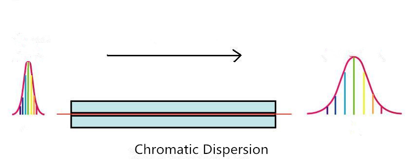
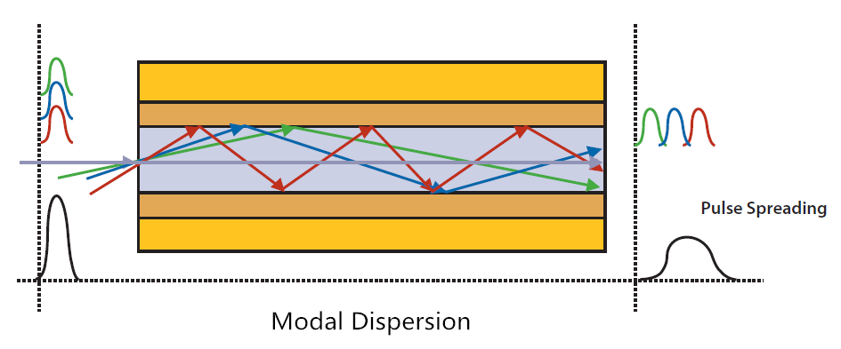
For single-mode fiber cable, it is chromatic dispersion that affects the transmission distance. This is because, the core of the single-mode fiber optic is much smaller than that of multimode fiber. So the transmission distance is longer than multimode fiber cable. For multimode fiber cable, modal dispersion is the main cause. Because of the fiber imperfections, these optical signals cannot arrive simultaneously and there is a delay between the fastest and the slowest modes, which causes the dispersion and limits the performance of multimode fiber cable.
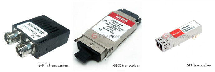
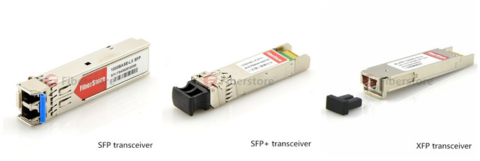
Like most of the terminals, fiber optic transceiver modules are electronic based. Transceiver modules play the role of EOE conversions (electrics-optics-electrics). The conversion of signals is largely depend on an LED (light emitting diode) or a laser diode inside the transceiver, which is the light source of fiber optic transceiver. The light source can also affect the transmission distance of a fiber optic link.
LED diode based transceivers can only support short distances and low data rate transmission. Thus, they cannot satisfy the increasing demand for higher data rate and longer transmission distance. For longer transmission distance and higher data rate, laser diode is used in most of the modern transceivers. The most commonly used laser sources in transceivers are Fabry Perot (FP) laser, Distributed Feedback (DFB) laser and Vertical-Cavity Surface-Emitting (VCSEL) laser. The following chart shows the main characteristics of these light sources.
| Light Source | Transmission Distance | Transmission Speed | Transmission Frequency | Cost |
| LED | Short Range
|
Low Speed | Wide Spectral width | Low Cost |
| FP | Medium Range | High Speed | Medium Spectral Width | Moderate Cost |
| DFB | Long Range | Very High Speed | Narrow Spectral Width | High Cost |
| VCSEL | Medium Range | High Speed | Narrow Spectral Width | Low Cost |
As the above chart mentioned, different laser sources support different frequencies. The maximum distance a fiber optic transmission system can support is affected by the frequency at which the fiber optic signal will be transmitted. Generally the higher the frequency, the longer distance the optical system can support. Thus, choosing the right frequency to transmit optical signals is necessary. Generally, multimode fiber system uses frequencies of 850 nm and 1300 nm, and 1300nm and 1550 nm are standard for single-mode system.
Bandwidth is another important factor that influences the transmission distance. Usually, as the bandwidth increases, the transmission distance decreases proportionally. For instance, a fiber that can support 500 MHz bandwidth at a distance of one kilometer will only be able to support 250 MHz at 2 kilometers and 100 MHz at 5 kilometers. Due to the way in which light passes through them, single-mode fiber has an inherently higher bandwidth than multimode fiber.
Splice and connector are also the transmission distance decreasing reasons. Signal loss appears when optical signal passes through each splice or connector. The amount of the loss depends on the types, quality and number of connectors and splices.
All in all, the above content introduces so many factors limiting the transmission distance, like fiber optic cable type, transceiver module’s light source, transmission frequency, bandwidth, splice and connector. As to these factors, different methods and choices can be taken to increase the transmission distance. Meanwhile, equipment like repeater and optical amplifiers are also useful to support the long distance transmission. So there must be some ways to help you increase the transmission distance.
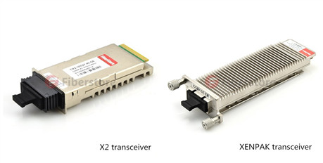 XENPAK transceiver is a pluggable transceiver for 10Gbps applications, specifically 10 Gigabit Ethernet. The electrical interface is called XAUI, which provides four 2.5Gbps signals to the transmitter, which multiplexes or serialize them into a single 10Gbps signal to drive the source. It uses a 70-pin electrical connector. The optical interface is usually a duplex SC.