Have You Remembered to Clean Your Fiber Optic Connectors?

Needless to say, keeping the cleanness of fiber optic connectors is essential to the high performance of optical devices. If the ferrule is damaged or broken, the whole connector will be useless. Therefore, protecting the connector ferrule from any possible contamination is very necessary. You need to take fiber optic cleaning seriously as a routine work to avoid extra loss.

Types of Contaminants

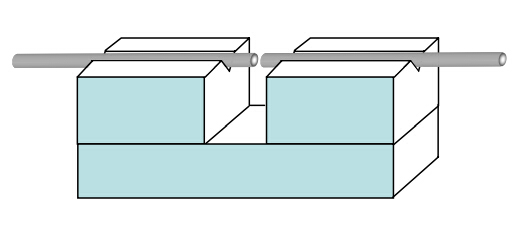
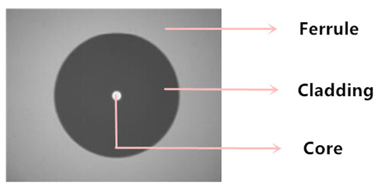
From the following picture, it is clear to see that the end face of a fiber consists three areas: ferrule, cladding and core. Once these parts are free from contamination, fiber optic cleaning is complete. Different contaminants may result in different cleaning solutions. Do you know how many kinds of contaminants are there on the fiber optic connectors?

fiber end face

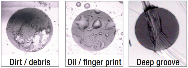
Generally speaking, there are three types of contaminants. Dusts and oils are the most common types. Cleaning these contaminants is easier as long as using the proper method. However, the contaminant of scratches, chips or pits sometimes may cause permanent defects on the end face. Then a new connector is required for replacement. Oils from your fingers will leave a noticeable defect easily seen with the use of a fiber scope, but it will also tend to trap dust against the fiber, which can lead to scratches on both the fiber connector and the optic it is being mated to. In addition, when installing or removing a fiber, small static charge on the ends will attract dust particles in the air. Therefore, putting on the fiber caps is a good precaution if the cable is not used.

end face contamination

Several Cleaning Methods

Nevertheless, if the connector is already polluted, using fiber caps will no longer be enough. Proper cleaning methods should be applied to remove the contaminants. Here lists some common cleaning methods:

  • Dry cleaning – No solvent is used for this type of method. The whole cleaning is processed in a dry condition.
  • Wet cleaning – Solvent is required for this method. Isopropyl alcohol is the most common solvent.
  • Non-abrasive cleaning – This method will not use any abrasive material to contact the connector end face.
  • Abrasive cleaning – This method will adopt abrasive tools such as lint-free wipes to do the cleaning.
Solutions for Fiber Optic Cleaning

If you have decided the cleaning method, then it is time to choose the right cleaning products. Common cleaning solutions on the market now are the pen cleaner, cassette cleaner, cleaning card and wipes.

Pen Cleaner

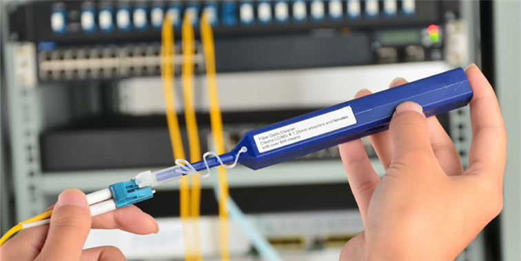
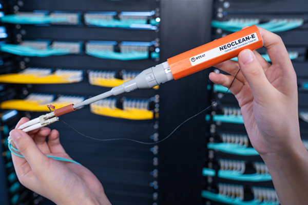
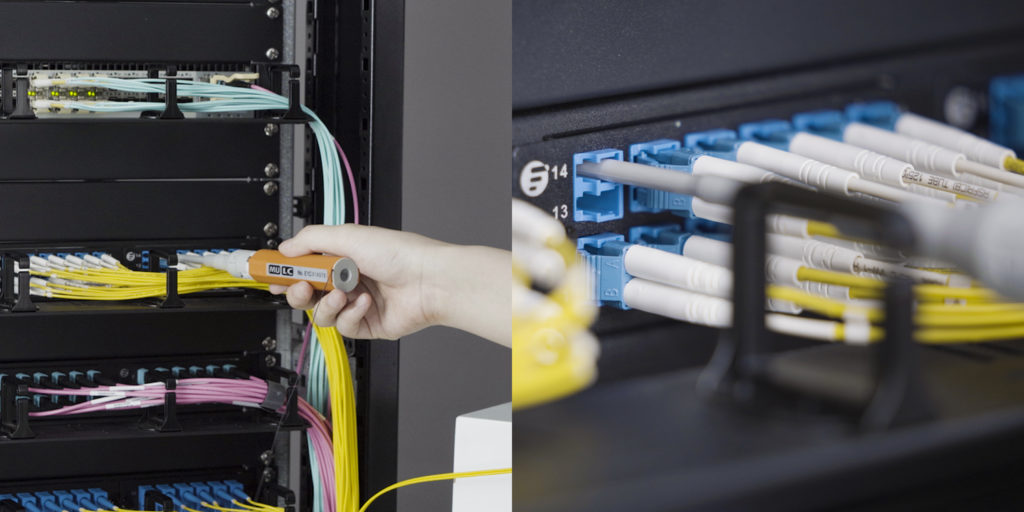
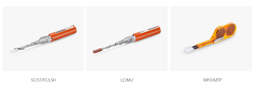
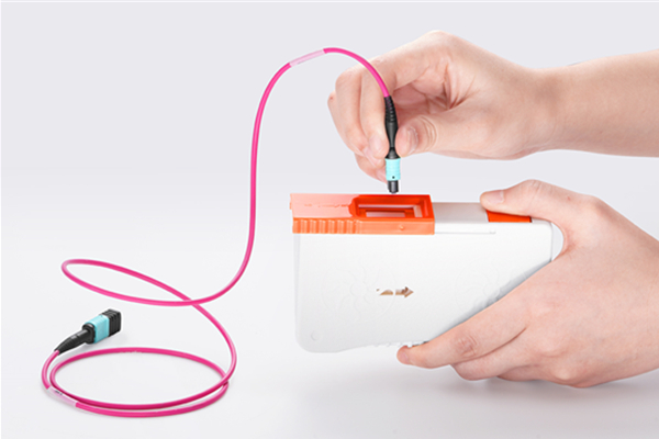
Pen cleaner is also named as one-push cleaner. It features an easy one push action, which quickly and effectively cleans the end-face of connectors. The cleaning tip is rotated to ensure the fiber end-face is effectively but gently cleaned. Usually available for 600 to 800 cleans.

pen cleaner for cleaning fiber optic connectors

Cassette Cleaner

Cassette cleaner or reel-type cleaner is ideal for lab, assembly line and field use. It enables simple push bottom shutter operation for quick and easy cleaning. Each cleaning tape is available for 400 to 500 cleans.

cassette cleaner

Cleaning Card & Wipes

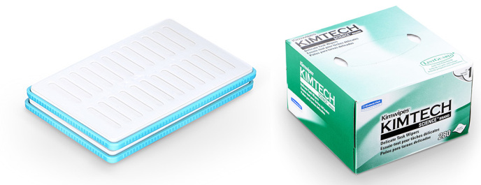
Cleaning card is made of the densely woven micro fiber cloth which effectively minimizes the static charge. Wipes are designed with minimal lint or dust to have little interference with the normal functioning of the equipment.

wipes and cleaning card

Common Cleaning Procedure

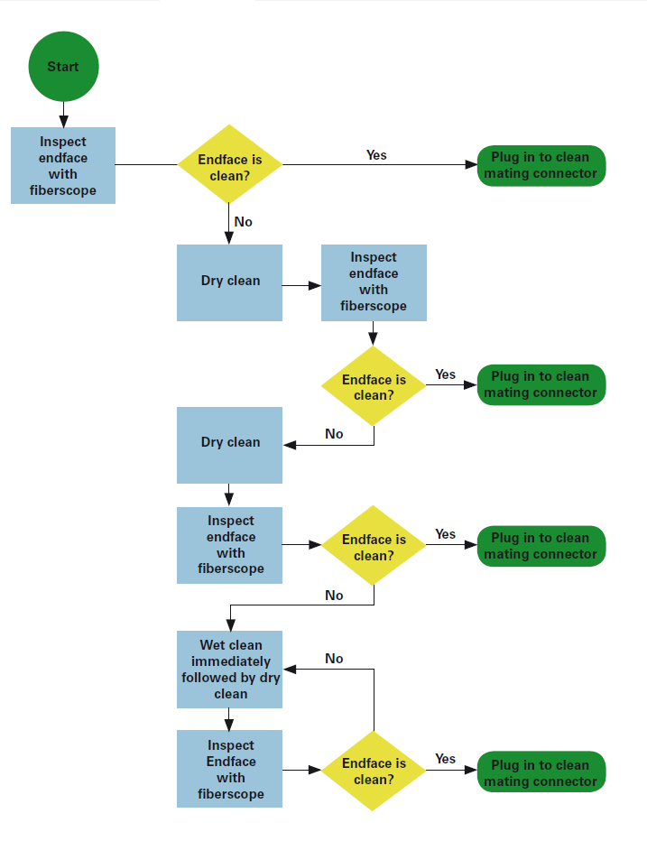
Follow these steps, you can always make a thorough fiber optic cleaning:

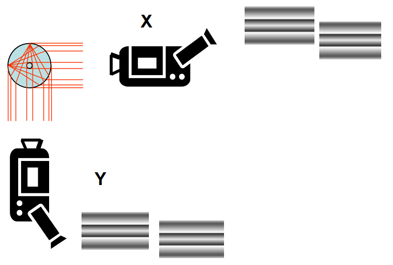
  • Step 1, inspect the fiber connector with a fiber scope.
  • Step 2, if the connector is dirty, clean it with a dry cleaning technique.
  • Step 3, inspect the connector.
  • Step 4, if the connector is still dirty, repeat the dry cleaning technique.
  • Step 5, inspect the connector.
  • Step 6, if the connector is still dirty, clean it with a wet cleaning technique followed immediately with a dry clean in order to ensure no residue is left on the end face.
  • Step 7, inspect the connector again.
  • Step 8, if the contaminant still cannot be removed, repeat the cleaning procedure until the end face is clean.
Conclusion

Constantly cleaning the fiber optic connectors can greatly decrease the link failures and unnecessary component replacement. Moreover, using professional tools is much safer and cleaner. Are you ready to clean the fiber optic connectors from now on?

Applying VFL for Fiber Cables Troubleshooting

Whenever you need to install or troubleshoot fiber cables, visual fault locator (VFL) is an easy and essential tool for quickly positioning the problem areas. As a fiber optic tester, VFL is used to trace optic fibers, check fiber continuity and find fiber breaks, damaged connectors, defective splices, tight bends in optical cables. Two basic types of VFL are pen shape VFL and hand held VFL. Pen shape VFL is very small with a pocket size to be carried anywhere. Hand held VFL has a range of connector bulkheads styles from universals to specific connector types. This article will lead you to know more information about VFL.

visual-fault-locator

Importance of VFL

VFL can pinpoint the exact fiber damage location, therefore technicians are able to diagnose and solve the problem in a timely manner which efficiently avoids further fiber damage. VFL is also used for conducting continuity tests and performing fiber identification. With the help of VFL, specialists can easily isolate high losses and faults in optical fiber cables. As we all know, a good cabling system is the pledge of a good data center. In order to maintain the perfect functioning of fiber optic cables, VFL is an indispensable tool to be applied for the routine trouble shooting.

How VFL Works?

The invisible light signals are typically transmitted at 1300 nm to 1650 nm wavelengths over fiber optic cables. Different from the way that OTDR (optical time-domain reflectometer) locates the faults by measuring the time of the incidence and the amplitude of the reflected pulses sent to the fiber optic cable, VFL uses powerful visible light at the wavelengths between 360 nm to 670 nm to visually and quickly locate the faults in the cables. When the visible light leaks out at a certain point of optical cable, it shows that the VFL has reached a fault. It is also easy to see light leaking through the plastic cable jackets under the right illumination of VFL. Generally, a VFL can work at the distance between 2 km to 5 km.

How to Use VFL?

Using VFL is not a difficult task. Just follow the steps to know the operation procedure:

  • Step one, remove the plastic connector covers from both ends of the fiber cable.
  • Step two, connect the VFL to one end of the fiber cable.
  • Step three, press the tester button and observe whether light emanates from the other end of the fiber. This gives a simple indication of the continuity of the fiber link.
  • Step four, repeat the above steps with other fiber cables to see if visual light is leaking out from a faulty splice. This may illustrate an easy way of carrying out visual fault locating on bad splices or joints.
  • Step five, disconnect all equipment, put the plastic covers back to the connector ends and return everything to the state it was.

Notes:

  • Point one, do not look directly into the VFL’s output.
  • Point two, cover the VFL’s output with the dust cap when it is not in use.
  • Point three, VFL is not recommended to be used on dark colored or armored cables.
Conclusion

VFL is an equipment for fiber testing, troubleshooting and measurement. It is ideal for locating a large number of defects that are hidden in an OTDR “blind-spot” or “dead-zone”. Fiber breaks, faulty connectors, sharp bends, bad splices and other similar faults can be visually located by VFL’s visual light injected into a fiber. VFL can boost productivity in the field by providing fast detection, precise fault location and ORL (optical return loss) measurements. If you don’t have it, better get one for your project.

UPC or APC – Which One to Choose?

When it comes to fiber optic cables, you might be curious about the description that contains UPC or APC. For example, what is LC UPC to LC UPC? And what is SC APC to SC APC? UPC and APC are actually two polish types of fiber ferrules. This article will help you explore the world of UPC and APC to know which one is the better solution for your network.

What is APC & UPC?

Return loss is inevitable when installing a connector on the end of fiber. It is a back reflection generated by the light source. However, severe light loss will damage the laser light sources and disrupt transmitted signals. Therefore, different polish connector ferrules are made to avoid serious return loss. UPC and APC are two widely used polish types. Here are some specific information about UPC and APC.

UPC, namely ultra physical contact, is evolved from PC with a better surface finish. UPC connector relies on machine polishing to deliver its low optical return loss characteristics. Its rounded finish created during the polishing process allows fibers to touch on a high point near the fiber core where light travels. In addition, when using the UPC connector, make sure your laser’s specifications can handle the return loss your UPC connector will generate.

UPC

APC, namely angled physical contact, is very different from UPC. The end face of APC connector is precisely polished at an 8-degree angle to the fiber cladding so that most return loss is reflected into the cladding where it cannot interfere with the transmitted signal or damage the laser source. But it is extremely difficult to field terminate an APC connector at 8 degrees with any consistent level of success. Therefore, if an APC connector is damaged in the field, it should be replaced with a factory terminated APC connector.

APC

How to Distinguish UPC from APC?

Many differences can be found between UPC and APC connectors:

Point one, end faces. As we have discussed before, UPC connectors are polished with no angle, but APC connectors is polished at an 8-degree angle.

Point two, ways of light reflection. Their different polish end faces directly lead to their differences in ways of light reflection. Any reflected light is reflected straight back towards the light source if an UPC connector is used. But the APC connector causes reflected light to reflect at an angle into the cladding instead of straight back toward the source.

Point three, return loss. Since their light reflection patterns are varied, their levels of return loss are also different. APC connector offers lower return loss of -65 dB than UPC of -50 dB. As a matter of fact, connectors can achieve better matching performance if return loss is lower.

Point four, connector color. This is the most obvious difference that can be seen from the surface. UPC connector usually has a blue body while APC connector has a green body.

Which One to Choose?

If you are still confused about which polish type to choose, the best way is to see whether their applications complies to yours. In general, the APC type has a better performance than the UPC type. APC is best for high bandwidth applications and long haul links. For example, FTTx (fiber to the x), passive optical network (PON) and wavelength-division multiplexing (WDM) that are more sensitive to return loss, thus APC is a better solution to offer the lowest return loss. However, massive employment of APC connectors will cause higher cost. In this way, UPC might be a better choice because cost budget is of equal importance.

Conclusion

UPC and APC are taken into consideration when choosing fiber optic patch cables. Both of them can reduce light loss and protect laser sources from damage. A wise selection should be based on your actual condition. Hope this article can provide you some help.

Guide to Fusion Splicer Selection

Optic fiber is now widely applied to networks around the globe. When it comes to actual operation, connecting fibers is a necessary task. And fusion splicer is an effective tool for fiber optic splicing. But choosing the right type of fusion splicer is still a challenge. In this article, we will talk about how to find the most matching fusion splicer.

Before discussing about different types of fusion splicer, let’s first have a look at the working principle and specific function of a fusion splicer. The fusion splicer is the device that uses heat to melt the ends of two optic fibers and combines them together into one fiber. By using the fusion splicer, the joint is permanent so that light signals can pass from one fiber to another with little link loss. The heating source of a fusion splicer can be a laser, a gas flame, a tungsten filament or a electric arc. And the most popular heating source at present is electric arc.

Nowadays, there are two types of fusion splicer according to different aligning systems. One is called the core alignment fusion splicer, the other is cladding alignment fusion splicer. If you can figure out the differences between these two types of fusion splicer, finding a right fusion splicer is no longer a problem.

Core Alignment Fusion Splicer

Core alignment is the most welcome fusion splicing technology at present. The splicer combines the image and light detection systems which can view the fibers cores in order to measure and monitor core position. Fiber cores are put in V-grooves and are aligned horizontally (X-axis), vertically (Y-axis) and in/out (Z-axis). The type of fusion splicer is adaptable for all kinds of fibers, such as single-mode or multimode fiber, good or bad fiber and splicing old fiber to new fiber. It is much more expensive but provides a more precised alignment.

Core-Alignment-Fusion-Splicer

Cladding Alignment Fusion Splicer

Cladding alignment is also called as passive alignment or fixed V-groove type. This type of fusion splicer relies on the accurate pre-alignment of fiber V-grooves that grip the outer surface or cladding of the fiber. Fiber cores are adjusted inwards and outwards. This type of fusion splicer is only available for multimode fiber or good single-mode fibers. As to cladding alignment fusion splicer, the cost is lower and alignment is faster, but its demand for the quality of fiber is higher or else will cause a lot of losses.

Cladding-Alignment-Fusion-Splicer

Suggestions For Fiber Optic Splicing

Though the two types of fiber optic splicing are different, the methods for better splicing are common. Here are some suggestions for fiber optic splicing:

1. Clean the fusion splicer before splicing. Any invisible contamination will cause tremendous problems when splicing the fibers.

2. In order to increase the alignment speed for fusion splicer, it is important to maintain and operate other tools, such fiber cleaver. A good cleaving will save time for splicing and decrease fiber loss.

3. Make sure the fusion parameters are adjusted minimally and methodically. The changes of parameters will also generate problems for your desired setting.

Conclusion

Selecting a suitable fusion splicer is beneficial to the splicing process. You may consider your needs and affordable cost to find the right fusion splicer. Core alignment fusion splicer has a better performance but a higher price than cladding alignment fusion splicer. Please choose your ideal fusion splicer wisely and do not forget to follow the normative operation for your splicing.

Introduction to LC/MU One-Push Cleaner

When the transmission of the light signal in optic fiber is affected or completely blocked, the main cause is sometimes to be the contamination on the end-faces of connectors or adapters. Therefore, it is extremely important to clean the pollution otherwise the transmission will be greatly influenced. But how can we make a quick and easy clean? The good news is that the problem can now be solved with only one push. The product of one-push cleaner is designed for the convenient and environmental cleaning of end-face contamination, such as road dust, skin oil residue, salt water residue, alcohol residue, vegetable residue, graphite dryer lint, hand lotion and distilled water residue.

one-push cleaner for 1.25mm ferrules

The LC/MU one-push cleaner is only available for 1.25mm ferrules, since it is the parameter standard for LC and MU products. Also, the cleaner should be discarded after 750 cleaning times to avoid further contamination. And the LC/MU one-push cleaner can be applied in two polish types of connectors as APC and PC.

The usage of LC/MU one-push cleaner is relatively simple for average people. When it is employed for LC/MU connectors, make sure just remove the cover dust cap. Next, connectors should be inserted into guide cap for a clean click. However, when it is applied for LC/MU adapters, the guide cap should also be removed. Then insert the cleaner tip into adapters with a click. In addition, please pay attention to the depth of adapters. If they are recessed adapters, the tip length should be extended to reach the adapter.

adapter cleaning

Of course, LC/MU one-push cleaner is just a small category of the one-push cleaner family. According to different types of connectors or adapters, there are also many diverse one-push cleaners, for example, the MTP/MPO one-push cleaner which includes the thumb wheels, the SC/ST/FC/LSH one-push cleaner which is used for 2.5mm ferrules and so on. Therefore, people should be careful about the product model before purchasing.

Besides, some fiber optic testers may provide help for the inspection before cleaning and maintenance after cleaning of connectors and adapters. For instance, optical power meter and visual fault locator can be used for detecting whether the light has power loss or is disconnected at a certain point so as to find the specific cleaning area, and the fiber identifier can be employed for the daily maintenance by checking whether the signal is transmitted uninterruptedly after cleaning.

As an easier tool for the cleaning of LC/MU connector and adapter, one-push cleaner is the top choice for everyone who is in charge of the cleaning in data center. With just one push, most of the contamination will be gone, and optic transmission will go back to normal again. For more information about LC/MU one-push cleaner, please visit our website at FS.COM.

Fiber Optic Splicing

Fiber optic splicing is one of the fiber optic terminations which creates a permanent joint between the two fibers. With the benefits of low light loss and back reflection, fiber optic splicing is a preferred method when the cable runs are too long for a single length of fiber or then joining two different types of cables together. There are two methods of splicing, fusion splicing and mechanical splicing.

Fusion Splicing

In fusion splicing (as following picture), a machine called fusion splicer is used to precisely align the two fiber ends. Then the glass ends are “fused” or “welded” together using some type of heat or electric arc. This produces a permanent connection between the fibers enabling very low loss light transmission (Typical loss: 0.1 dB). Fusion splicing has the best return loss performance of all the mating and splicing techniques.

fusion-splice

Fusion Splicing Steps
    • Prepare the fiber. Strip the protective coatings, jackets, tubes, strength members, etc. and only leave the bare fiber showing. Please pay attention to keep the fiber clean.
    • Cleave the fiber. Choose a good fiber cleaver. The cleaved end must be mirror-smooth and perpendicular to the fiber axis to obtain a proper splice. But the cleaver is not used to cut the fiber. It’s only used to produce a cleaved end that is as perpendicular as possible.
    • Fuse the fiber. Align the fusion splicer unit and use an electrical arc to melt the fibers, permanently welding the two fiber ends together. Alignment can be manual or automatic.
    • Protect the fiber – To ensure the splice not break during normal handling, you must protect the fiber from bending and tensile forces. A typical fusion splice has a tensile strength between 0.5 and 1.5 lbs and will not break during normal handling but it still requires protection from excessive bending and pulling forces.
Mechanical Splicing

Mechanical splicing (as following picture) aligns and mates the end face of two cleaned and cleaved fiber tip together. It’s a reusable splice. The mechanical splice will have an index matching fluid that eliminates the fiber-to-air interface, there by resulting in less back reflections. Mechanical splices are often used when splices need to be made quickly and easily.

mechanical-splicing

Mechanical Splicing Steps
  • Prepare the fiber. Strip the protective coatings, jackets, tubes, strength members, etc. and only leave the bare fiber showing. Please pay attention to keep the fiber clean.
  • Cleave the fiber. This one is the same to the fusion splicing step. But the cleave precision is as critical.
  • Mechanically join the fibers. This method doesn’t use heat. Simply put the fiber ends together inside the mechanical splice unit. The index matching fluid inside the mechanical splice apparatus will help couple the light from one fiber end to the other. Older apparatus will have an epoxy rather than the index matching fluid holding the cores together.
  • Protect the fiber – the completed mechanical splice provides its own protection for the splice.
Which One Should You Choose?

To decide which fiber splicing method you should choose, you may take two important factors into consideration. First, it’s the cost. Mechanical splicing has a low initial investment ($1,000—$2,000) but costs more per splice ($12-$40 each). While the initial investment is about at least $15,000 and per splice cost is about $0.50 – $1.50. Second, it’s the performance. Fusion splicing offers a high degree performance of lower loss and less back reflection than mechanical splicing.

By the comparison of the cost and performance of two methods, now you know which one is suitable for your applications. If you have enough money and need more precise alignment for lower loss, you could buy a fusion splicing machine. If you just have a small budget and should make a quick splice, then you can choose mechanical fiber optic splice.

Originally published at http://www.china-cable-suppliers.com/fiber-optic-splicing.html

Visual Fault Locator Overview

Whether install new fiber links or troubleshooting an existing network, the faster you can locate a problem, the faster you can fix it. To locate the faults in fiber optic cables in a short time, various fiber optic testers are being invited to locate the faults of the fiber optic cable, like OTDR (optical time-domain reflectometer). However, OTDR has dead zone during the testing. Another simple and useful tester which can work in an OTDR dead zone is usually being used to work as an accessory of OTDR. It is known as VFL (visual fault locator) which can also work alone to locate the faults in fiber optic cable in a time saving manner in some situations.

What Is VFL?

Visual fault locator is now one of the most commonly used fiber optic testing devices to trace optical fibers, check fiber continuity and find faults such as breaks, bad splices and tight, sharp bends in fiber optic cable. The most popular visual fault locators are pen shape VFL and hand-held VFL, which are showed in the following picture respectively.

pen shape VFL and hand-held VFL

How VFL Works

The light used for transmit signals over fiber optic is usually at 1300 to 1650nm wavelength which is invisible to naked eyes. Unlike OTDR which measures the time of the incidence and the amplitude of the reflected pulses sent to the fiber optic cable to locate the faults, VFL uses powerful visible light at the 360 to 670nm wavelength injecting to a fiber to visually and directly locate the faults in fiber optic cable. The visible light travels along the core until it reaches a fault, where it leaks out. Light leaking through the fault can be seen through plastic coating and jackets under suitable illumination. This is how VFL locates the faults in fiber optic cable.

Visual fault locators radiate in continuous wave (CW) or pulse modes. The glint of the light source in VFL is usually at 1 or 2 Hz, kHz range is also being provided in today’s market. The output power is generally at 1 mW or less. The working distance of a VFL is usually in the range of 2 to 5 km.

How to Use VFL

VFL is very easy to use. The steps to use a VFL are provided as following:

  • Step One: remove the plastic connector covers from both ends of the test fiber cable.
  • Step Two: connect the fiber optic visual fault locator one end of the fiber. Press the tester button and observe that light emanates from the other end of the fiber. This gives a simple indication of the continuity of the fiber link.
  • Step Three: repeat with several other fibers. Check for light that can be seen leaking from a faulty splice. This may illustrate an easy way of carrying out visual fault finding on bad splices or joints.
  • Step Four: disconnect all equipment, put the plastic covers back on the connector ends and return everything to the state it was in before you started the practical so that the next group can carry out the practical in full.

VFL

Notes during the using of a VFL:

  • 1.Never look directly into the VFL’s output.
  • 2.Cover the VFL’s output with the dust cap when the VFL is not in use.
  • 3.Not recommended for use on dark colored or armored cables.

Using simple but useful technical principle, visual fault locator individually can provide an economic and time saving solution to locator faults in fiber optic cables in some cases. While working as an accessory of OTDR, VFL, together with OTDR, can provide the fiber technician the best solution to locate fiber faults.

Make the Right Choice of Splicing

Fiber splicing is used to permanently join two optical fibers where no additional changes are expected to be made to those fibers at that juncture. Compared with joints by connectors, fiber splicing typically results in lower light loss and back reflection.

There are two methods of fiber optic splicing: fusion splicing and mechanical splicing. Both of the two are functioning the same. However, they have their own advantages and disadvantages, which should be acknowledged before choosing of the methods of splicing which best fit the economic and performance objectives.

Fusion Splicing VS. Mechanical Splicing

The following text will make a comparison between mechanical splicing and fusion splicing from several aspects (process, time requested, performance and cost) to find the best choice of splicing.

The biggest difference between mechanical splicing and fusion splicing can be figured out by their literally meaning. Mechanical splicing is mechanically joining the fibers ends together which is quick and effective. While fusion splicing is a method of fusing fibers together using arc welding which is fairly complex and requires much more skill than mechanical splicing.

Process: The first three steps of mechanical splicing and fusion splicing before connecting the fibers ends are generally the same.
  • Step one: strip the protective coatings, jackets, tubes, strength members, etc. leaving only the bare fiber showing.
  • Step two: cleave the fiber with a fiber optic cleaver. The cleaved end for fusion splicing must be mirror-smooth and perpendicular to the fiber axis to obtain a proper splice. As to mechanical, the cleaving process is identical to the cleaving for fusion splicing but the cleave precision is not as critical.
  • Step three: clean the fiber.
  • Step four: after cleaning the fiber, the connecting step starts.
    For fusion splicing, fusing fiber contains alignment and heating. Once properly aligned the fusion splicer unit then uses an electrical arc to melt the fibers, permanently welding the two fiber ends together.
    Mechanical splicing does not need heating. Simply position the fiber ends together inside the mechanical splice unit. The index matching gel inside the mechanical splice apparatus will help couple the light from one fiber end to the other.
  • Step five: protect the fiber
    Fusion splicing—using heat shrink tubing, silicone gel and/or mechanical crimp protectors will keep the splice protected from outside elements and breakage.
    Mechanical splicing—the completed mechanical splice provides its own protection for the splice.

fusion-splicing-tools

Time Requested: mechanical splicing is fast and effective, which is suitable for some emergency situations. However, fusion splicing is more skilled and need more time to be finished.

Performance: with mechanical splicing, the fibers usually have loss of 0.3dB. However, with fusion splicing, the fibers generally have a loss of 0.1dB and the fiber splices are usually stronger.

Cost:mechanical splicing has a low initial investment ($1,000-$2,000) but costs more per splice ($12-$40 each). While the cost per splice for fusion splicing is lower ($0.50-$1.50 each), the initial investment is much higher ($15,000-$50,000 depending on the accuracy and features of the fusion splicing machine being purchased). The more precise you need the alignment (better alignment results in lower loss) the more you pay for the machine.

Many companies now invest fusion for networks, especially for long haul single-mode networks. However, they also use mechanical splicing for shorter, local cable runs. Consider the requests for performance quality, time, situations and the capacity of economics before choosing the fittest method of splicing.

Fiber Optic Cleaning – Fight Against Dust

Fiber optic connectors are very sensitive to contaminants like dust, oil and other dirt which can have great impact on the overall optical network, and can reduce its performance and maximum distance. Dust as small as 1 µm can have a noticeable effect on the connector’s attenuation (in excess of 0.5dB). Thus, fiber optic cleaning is one of the most basic procedures to main the operation of optical network system. It’s no exaggeration to say that cleaning consideration is the number one issue in fiber optic cable technology today.

Dust Is Everywhere

It seems that the dust, one of the biggest enemy in the fiber optic communication system, can always find its way to reach the fiber optic connector interface. When a fiber optic connector is mated or unmated, both the plug and receptacle might be polluted by the dust, oil from our fingers or other contaminants. The oil can leave a noticeable defect on the interface of the fiber optic connector, the oil also tends to trap dust against the fiber. To maintain the well operation of optical network, many fiber optic cleaning products and methods are being invented to fight again contaminants like dust.

Tips on Fiber Optic Cleaning

There are two main methods of cleaning based on the material used to clean the fiber optic. One is known as dry clean which is optic cleaning without using any solvent, the other is wet clean during which solvent, usually IPA (isopropyl alcohol) is used. Sometimes, the two methods should be combined. The following picture shows the suggested cleaning approach.

fiber optic cleaning process

The following are some tips which might be useful during fiber optic cleaning:

  • Both sides of the connectors should be cleaned, as dirt might be transferred from one to the other.
  • Keep dust caps on the connector, but do remember to verify that the dust caps are clean.
  • Do not just clean the end-face. The body of the connector ferrule should also be cleaned.
  • Do the cleaning in a clean, low-dust environment
  • You should not touch any transmissive or reflective surface of your optic and never reuse a lens tissue.

With proper handling and cleaning of your fiber optic, you can prevent damage and ensure their continued performance.

7 Factors to Consider before Selecting An OTDR

An OTDR (Optical Time Domain Reflectometer) is a fiber optic tester for the characterization of optical networks that support telecommunications. The purpose of an OTDR is to detect, locate, and measure elements at any location on a fiber optic link. An OTDR needs access to only one end of the link and acts like a one -dimensional radar system. By providing pictorial trace signature of the fibers under test, it’s possible to get a graphical representation of the entire fiber optic link.

Fiberstore2405 OTDR

An OTDR can be used to measure optical distance including locations of the elements like splices, connectors, splitters, multiplexers and faults, as well as end of fiber. Loss and Optical Return Loss (ORL)/Reflectance, such as loss of splices and connectors, ORL of link or section, reflectance of connectors and total fiber attenuation can also be tested by OTDRs.

Not all OTDR are made the same. There are various kinds of OTDR models available, addressing different test and measurement needs. The choosing of an OTDR is based on applications. By thinking of the following questions, you can roughly know what kind of OTDR you need.

  • What kind of networks will you be testing? LAN, metro, long haul?
  • What fiber type will you be testing? Multimode or single-mode?
  • What is the maximum distance you might have to test? 700 m, 25 km, 150 km?
  • What kind of measurements will you perform? Construction(acceptance testing), troubleshooting, in-service?

JDSU MTS-4000 OTDR

Fiberstore offers you 7 factors to help you figure out which OTDR best fits your applications.

  • Size and Weight: important if you have to climb up a cell tower or work inside a building.
  • Display Size: 5″ should be the minimum requirement for a display size; OTDRs with smaller displays cost less but make OTDR trace analysis more difficult.
  • Battery Life: an OTDR should be usable for a day in the field; 8 hours should be the minimum.
  • Trace or Results Storage: 128 MB should be the minimum internal memory with options for external storage such as external USB memory sticks.
  • Bluetooth and/or WiFi Wireless Technology: wireless connectivity enables easily exporting test results to PCs/laptops/tablets.
  • Modularity/Upgradability: a modular/upgradable platform will more easily match the evolution of your test needs; this may be more costly at the time of purchase but is less expensive in the long term.
  • Post-Processing Software Availability: although it is possible to edit and document your fibers from the test instrument, it is much easier and more convenient to analyze and document test results using post-processing software.

Before selecting an OTDR, consider the applications that the instrument will be used for and check the OTDR’s specifications to ensure that they are suited to your applications.

Fiberstore OTDR Solution

Fiberstore OTDRs are available with a variety of fiber types and wavelengths, including single mode fiber, multimode fiber, 1310nm, 1550 nm, 1625 nm, etc. It also supplies OTDRs of famous brands, such as JDSU MTS series, EXFO, YOKOGAWA AQ series and so on. You can find the OTDR best fit your applications in Fiberstore.

Several Types of Fiber Optic Tool Kits

Every professional fiber optic installer needs a complete set of fiber optic tools and test equipment. The tools used in the kits are thoughtfully assembled and are stored in high quality cases, keeping them safe, neat and in proper working order. This article will introduce several types of fiber optic tool kits.

Kits for Fiber Optic Splicing
HW-6300N

This professional tool kit is ideal for optical fiber fusion splicing. It includes Clauss Fiber Optic Strippers (CFS-2), Fiber Optic Kevlar Cutter (KC-1), Optical Fiber Jacket Stripper (HW-108), 7″ Lineman’s Pliers, 6″ Side Cut Pliers 130mm, 6″ needle Nose Pliers 135mm, Steel Wire Cutter (HWC-6), Monkey Wrench, Metal Saw (small), Precision Tweezers, Straight Screwdriver (mid-sized), Cross Screwdriver (mid-sized), Fiber Optic Cleaning Swab, Fiber Optic Cable Stripper (horizontal 3-32mm),Pen Style Fiber Optic Cutter, Strraight Screwdriver (small), Cross Screwdriver (small), RCS Fiber Optic Cable Stripper (horizontal and vertical), Precision Screw Set (6pc), Hex Key Set (9pc), Black Marker, Utility Knife, Measuring Tape, Blow Brush, Alcohol Bottle (no alcohol included), Rugged Carrying Tool Case (430mm X 330mm X135mm).

Fusion Splicing Tool Kit HW-6300N

FS-04U

FS-04U tool kit is mainly used for construction, inspection and maintenance of fiber optic cable (aerial, duct and direct buried fiber optic cable, etc) in Telecommunications, Power, Defense and IT infrastructure. It provides in service stripping and solves the difficulty of stripping loose tube.

The equipment could be still in operation after the jacket and loose tube is stripped. By placing with main standby fiber, it will avoid service interruption or shorten the interruption span. According to its characteristics of maintenance and construction of fiber optic cable, emergency repair on fiber optic cable is under three conditions: restore and replace fiber optic cable; restore the broken fiber; split fiber optic cable.

In the premise of no communication interruption, it improves maintenance quality of fiber optic cable and minimizes economic loss to the maximum. The suitcase is made of once forming high strength plastic, strong, shock-proof and of long use life.

Kits Content: Fiber optic stripper CFS-2, KEVLAR Scissor KC-1, Fiber Jacket Stripper HW-108, Pocket Visual Fault Locator (Optional), High Precision Fiber Cleaver (Optional), Universal fiber Cable Slitter (3.2-35mm), Longitudinal Cable Sheath Slitter KMS-K, Ideal 45-162 Buffer tube stripper, 6-IN-1 Mini Pen-style Scredriver, 4-IN-1 Magnetic Quick Change Scredriver, 6″ Needle Node Pliers 135mm, 6″ Side Cut Pliers 130mm, Round Cable Cutter (HW-19c), 7Pcs Folding type hex key set (inch), 6″ Adjustable wrench, Fiber Optic Splice Protection Sleeve-Single Fiber 60mm 100PCS, 250ml Bottle of Alcohol with Lock, 2.5mm Foam Tipped Fiber Optic Swab 50/pkg, Pre-Moistened Alcohol Wipes 10PCS, 3M Electrical Tape, Blow Brush (MS-15C), Utility knife, 3.5M Tape Measure, Precision tweezer, Black Marker, Carrying Tool Case (430×330×135mm).

Fiber Optic Cable Fusion Splicing Tool Kit FS-04U

Kits for Fiber Optic Polishing

The fiber optic polishing tool kit FS-03E is a kind of kit that including Fiber optic stripper CFS-2, KEVLAR Scissor KC-1, Cabide Scibe Tool TTK-174A, Fiber Jacket Stripper, Universal Connector Crimp Tool, 200x Deluxe fiber microscope HW200ME, Epoxy Application Syringe 3ml, 5μm Polish Film,1μm Polish Film, 0.5μm Polish Film, 2.5mm Universal Polish Puck, Rubber Polish Pad, Glass Polish Plate,Safety Glasses, IPA Cleaning Wipes(PreMoistened), LintFree Wipes, Cleaning Swabs 25pcs/bag, Water Bottle Black Marker, Carrying Tool Case(385×275×110mm).

fiber optic polishing tool kit FS-03E

Kits for Fiber Optic Testing

The FTTH fiber optic test tool kit FS-1001 is a kind of kit that including Precision Fiber Cleaver, Optical Power Meter, Visual Fault Locator (10km), Round Cable Slitter, Fiber Optic Kevlar Cutter, Fiber Optic Stripper CFS-2, 6″Side Cut Pliers, 250ml Alcohol dispensing bottle with locked, Kim Wipes, Carrying Tool Case (385x275x110mm).

FTTH fiber optic test tool kit FS-1001

Kits for Fiber Connector Termination

Fiber connector termination tool kit FB-3601—fiber optic polishing and fiber termination tool kit, contains all of the latest popular fiber optic tools and consumable material necessary for epoxy and polish connector terminations (SC/ST/FC and LC connectors). Here is a figure for you.

Kits Content: Fiber optic stripper CFS-2, KEVLAR Scissor KC-1, Cabide Scibe Tool TK-17A, Fiber Jacket Stripper HC-18, Universal Connector Crimp Tool Jw-336J, IDEAL 45-162 Buffer tube stripper, Round Cable Jacket Stripper HE-335, LC/MU adapter for 400x Microscope, Flexible piano wire, 4-IN-1 Magnetic Quick Change Scredriver, Precision tweezer, 24 Port Connnector, Hot Oven (AC110v or AC220v), Epoxy Application Syringe 3ml, 5μm Polish Film 10pcs, 1μm Polish Film 10PCS, 0.5μm Polish Film 10PCS, 2.5mm Universal Polish Puck, LC/MU polish puck, 5.9″ Rubber Polish Pad, 5.9″ Glass Polish Plate, Large Black Work Mat (15″×11″), 10 IPA Fiber Cleaning Wipes(Pre-Moistened), KimWipes 280piece/box, Cleaning Swabs 50/pkg, 3M Electrician Tape, Utility knife, Utility component box, Black Marker, Carrying Case (430x330x135mm).

Fiber connector termination tool kit FB-3601

Kits for Optical Fiber Construction

There are many different kinds and models of tools in this optical fiber construction tool kit CTN-226 which are very important in the fiber optic installation and maintenance works.

Kits Content: Coaxial cable stripper, 3m Tapeline, Powerful plier, Powerful straight scissors, Powerful bent scissors, Black Marker, Mini torch, Cable stripping plier, Utility knife, 8″adjustable wrench, Wire cutter, 6PCS insulated screwdriver set, Multi socket & screwdriver set, 9PCS hex key set, Cleaning ball, 6″flat nose plier, 6″long nose plier, 6″diagonal cutting plier, Test screwdriver, 8PCS precision screwdriver set, Tweezer, Pipe cutter, Screwdrivers, +6Χ150mm -6Χ150mm, Aluminum-make tool case.

optical fiber construction tool kit CTN-226

Conclusion

Fiber optic splicing kits include mechanical splice kit and fusion splicing kit which are used in fiber optic splicing. Fiber optic test tool kit is used to inspect fiber optic equipment during the production or for trouble shooting. Fiber termination kit is used for fiber termination and contains tools those used to strip, prep, terminate, crimp, polish and inspect fiber optic cable connectors. FS.COM provides various types of fiber optic tool kits including mechanical splice kits, fusion splicing kits, fiber optic test tool kits, fiber termination kits, optical fiber construction tool kits and fiber optic polishing tool kits. If you want to know more details, you can visit our site.